EP1452208A1 - Improved golf club shaft and grip and method for gripping golf club - Google Patents
Improved golf club shaft and grip and method for gripping golf club Download PDFInfo
- Publication number
- EP1452208A1 EP1452208A1 EP04001269A EP04001269A EP1452208A1 EP 1452208 A1 EP1452208 A1 EP 1452208A1 EP 04001269 A EP04001269 A EP 04001269A EP 04001269 A EP04001269 A EP 04001269A EP 1452208 A1 EP1452208 A1 EP 1452208A1
- Authority
- EP
- European Patent Office
- Prior art keywords
- shaft
- hand
- grip
- golfer
- controlling
- Prior art date
- Legal status (The legal status is an assumption and is not a legal conclusion. Google has not performed a legal analysis and makes no representation as to the accuracy of the status listed.)
- Withdrawn
Links
Images


Classifications
-
- G—PHYSICS
- G10—MUSICAL INSTRUMENTS; ACOUSTICS
- G10K—SOUND-PRODUCING DEVICES; METHODS OR DEVICES FOR PROTECTING AGAINST, OR FOR DAMPING, NOISE OR OTHER ACOUSTIC WAVES IN GENERAL; ACOUSTICS NOT OTHERWISE PROVIDED FOR
- G10K5/00—Whistles
-
- A—HUMAN NECESSITIES
- A63—SPORTS; GAMES; AMUSEMENTS
- A63B—APPARATUS FOR PHYSICAL TRAINING, GYMNASTICS, SWIMMING, CLIMBING, OR FENCING; BALL GAMES; TRAINING EQUIPMENT
- A63B53/00—Golf clubs
- A63B53/14—Handles
-
- A—HUMAN NECESSITIES
- A63—SPORTS; GAMES; AMUSEMENTS
- A63B—APPARATUS FOR PHYSICAL TRAINING, GYMNASTICS, SWIMMING, CLIMBING, OR FENCING; BALL GAMES; TRAINING EQUIPMENT
- A63B53/00—Golf clubs
- A63B53/007—Putters
-
- A—HUMAN NECESSITIES
- A63—SPORTS; GAMES; AMUSEMENTS
- A63B—APPARATUS FOR PHYSICAL TRAINING, GYMNASTICS, SWIMMING, CLIMBING, OR FENCING; BALL GAMES; TRAINING EQUIPMENT
- A63B60/00—Details or accessories of golf clubs, bats, rackets or the like
-
- A—HUMAN NECESSITIES
- A63—SPORTS; GAMES; AMUSEMENTS
- A63B—APPARATUS FOR PHYSICAL TRAINING, GYMNASTICS, SWIMMING, CLIMBING, OR FENCING; BALL GAMES; TRAINING EQUIPMENT
- A63B49/00—Stringed rackets, e.g. for tennis
- A63B49/02—Frames
- A63B49/08—Frames with special construction of the handle
-
- A—HUMAN NECESSITIES
- A63—SPORTS; GAMES; AMUSEMENTS
- A63B—APPARATUS FOR PHYSICAL TRAINING, GYMNASTICS, SWIMMING, CLIMBING, OR FENCING; BALL GAMES; TRAINING EQUIPMENT
- A63B60/00—Details or accessories of golf clubs, bats, rackets or the like
- A63B60/06—Handles
- A63B60/08—Handles characterised by the material
-
- A—HUMAN NECESSITIES
- A63—SPORTS; GAMES; AMUSEMENTS
- A63B—APPARATUS FOR PHYSICAL TRAINING, GYMNASTICS, SWIMMING, CLIMBING, OR FENCING; BALL GAMES; TRAINING EQUIPMENT
- A63B60/00—Details or accessories of golf clubs, bats, rackets or the like
- A63B60/06—Handles
- A63B60/10—Handles with means for indicating correct holding positions
-
- A—HUMAN NECESSITIES
- A63—SPORTS; GAMES; AMUSEMENTS
- A63B—APPARATUS FOR PHYSICAL TRAINING, GYMNASTICS, SWIMMING, CLIMBING, OR FENCING; BALL GAMES; TRAINING EQUIPMENT
- A63B60/00—Details or accessories of golf clubs, bats, rackets or the like
- A63B60/06—Handles
- A63B60/12—Handles contoured according to the anatomy of the user's hand
-
- A—HUMAN NECESSITIES
- A63—SPORTS; GAMES; AMUSEMENTS
- A63B—APPARATUS FOR PHYSICAL TRAINING, GYMNASTICS, SWIMMING, CLIMBING, OR FENCING; BALL GAMES; TRAINING EQUIPMENT
- A63B60/00—Details or accessories of golf clubs, bats, rackets or the like
- A63B60/06—Handles
- A63B60/14—Coverings specially adapted for handles, e.g. sleeves or ribbons
-
- A—HUMAN NECESSITIES
- A63—SPORTS; GAMES; AMUSEMENTS
- A63B—APPARATUS FOR PHYSICAL TRAINING, GYMNASTICS, SWIMMING, CLIMBING, OR FENCING; BALL GAMES; TRAINING EQUIPMENT
- A63B60/00—Details or accessories of golf clubs, bats, rackets or the like
- A63B60/06—Handles
- A63B60/20—Handles with two handgrips
Definitions
- the present invention relates to an improved golf club shaft and grip and an improved method of gripping a golf club.
- Golf is a recreational and competitive sport that is a popular with large numbers of people of all ages.
- One of the skills necessary to play the sport well is the ability to maintain control of the golf club before, during, and after swinging the club to contact the golf ball. This skill is particularly important when putting. Many golfers, however, struggle to maintain the proper attitude of the golf club during the swing when using a conventional grip. Thus, the golf club strikes the golf ball at an incorrect angle, causing the golf ball to travel in an undesirable direction.
- U.S. Patent No. 3,679,207 discloses the construction of a golf putter that allows the golfer to use a type of croquet stance instead of the conventional golf stance.
- the shaft of the patented club is considerably longer than a conventional putter and is used by gripping the club at the end of the shaft with one hand while gripping the shaft at the center of balance with the other hand, thus creating a type of fulcrum effect to prevent extraneous motion of the club.
- 4,592,552, and D201,250 disclose extending the shaft of a golf club above a central grip, resulting in the club having approximately the same weight above as below the grip position. Such counter-weighting is also thought to control extraneous motion of the club during a swing.
- the improved golf club shaft and grip and method for gripping a golf club of the present invention proposes to provide golfer with golf club having a club head attached to a shaft via a hosel, wherein the shaft comprises a plurality of alternating circular and rectangular cross-sections extending from the top end of the shaft (opposite the hosel).
- a grip covering a portion of the shaft closely follows the alternating cross-sectional contour of the shaft.
- the rectangular cross-sections allow the shaft of the golf club to fit between chosen fingers on either hand of a golfer, thus stiffening the golfer's grip on the club without creating additional tension in the golfer's arms, which can cause extraneous motion. Further, such a grip allows the golfer's wrists to remain aligned with the hands, again providing a more controlled grip and, subsequently, swing of the golf club.
- the present invention also provides different grip configurations that can be mounted on conventional golf club shafts. These grip configurations provide various locations at which a golfer may grip the golf club shaft during a golf swing.
- the present invention also teaches a method for holding a golf club on which a preferred embodiment of the shaft and/or grip are used, the method providing additional stability during the swing.
- Fig. 1 is a perspective view of a golf club according to one of the preferred embodiments of the present invention, illustrating a golfer with the golf club in preparation of swinging the golf club;
- Fig. 2 is a side elevation illustrating the shape of a preferred embodiment of the golf club shaft and grip
- Fig. 3 is a magnification of an area of Fig. 2, illustrating the transition between club shaft and grip profiles;
- Fig. 4 is a cross-section of the golf club of Fig. 2, taken along the line 4-4, illustrating one profile of the club shaft and grip;
- Fig. 5 is a cross-section of the golf club of Fig. 2, taken along the line 5-5, illustrating a second profile of the club shaft and grip;
- Fig. 6 is a front elevation of the golf club of Fig. 2, illustrating the profiles of the club shaft and grip;
- Fig. 7 is a side elevation, illustrating a golf club having conventional shaft and grip profiles
- Fig. 8 shows a golf club shaft similar to that in Fig. 7, illustrating an embodiment of a grip of the present invention surrounding the club shaft;
- Fig. 9 shows a golf club shaft similar to that in Fig. 7, illustrating another embodiment of a grip of the present invention surrounding the club shaft;
- Fig. 10 shows a golf club shaft similar to that in Fig. 7, illustrating another embodiment of a grip of the present invention surrounding the club shaft;
- Fig. 11 shows a golf club shaft similar to that in Fig. 7, illustrating another embodiment of a grip of the present invention surrounding the club shaft;
- Fig. 12 shows a golf club shaft similar to that in Fig. 7, illustrating another embodiment of a grip of the present invention surrounding the club shaft;
- Figs. 13-16 are a series of partial perspective views of a golf club shaft according to one of the preferred embodiments of the present invention, illustrating a method of gripping a golf club shaft according to one of the preferred embodiments of the present invention
- Fig. 17 shows a golf club shaft similar to that in Fig. 13, illustrating another embodiment of a method a gripping a golf club shaft;
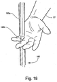
- Fig. 18 shows a golf club shaft similar to that in Fig. 13, illustrating another embodiment of a method a gripping a golf club shaft;
- Fig. 19 shows a golf club shaft similar to that in Fig. 13, illustrating another embodiment of a method a gripping a golf club shaft;
- Figs. 20-21 are a series of partial perspective views of a golf club shaft according to one of the preferred embodiments of the present invention, illustrating a method of gripping a golf club shaft according to one of the preferred embodiments of the present invention
- Figs. 22-24 are a series of partial perspective views of a conventional golf club shaft, illustrating a method of gripping a golf club shaft according to one of the preferred embodiments of the present invention.
- Fig. 25 is a cross-section of the golf club similar to that in Fig. 5, illustrating placement of fingers about a golf club shaft using a method of gripping a golf club shaft according to one of the preferred embodiments of the present invention.
- a typical golf club 75 comprises a head 45, a hosel 55 and a shaft 65.
- the shaft 65 has a top end 67 and a bottom end 69.
- the bottom end 69 of the shaft 65 is attached to the hosel 55.
- the club head 45 is attached to the hosel 55 opposite the shaft 65.
- a grip 85 surrounds a portion of the shaft 65, generally starting at the top end 67 of the shaft 65 and extending along the shaft 65 to a position intermediate the top end 67 and the bottom end 69 of the shaft 65.
- a golfer 25 typically holds the golf club 75 by grasping the golf club 75 at the grip 185.
- the club shaft 165 shown in Figures 1-6 comprises three parts: an upper part U, a lower part B and a middle part M intermediate that upper and lower parts U, B.
- the upper and lower parts U, B comprise cylinders having circular cross-sections of a defined and uniform diameter.
- the middle part M of the shaft 165 comprises a plurality of alternating rectangular 165b and circular 165a and cross-sectional areas.
- the circular cross-sections 165a are uniformly cylindrical and have the same diameter as that of the upper and lower parts U, B of the shaft 165.
- the rectangular cross-sections 165b have a length L, a width W and a height H.
- the length L of the rectangular cross-sections 165b is approximately the same as the diameter of the circular cross-sections 165a.
- the width W of the rectangular cross-sections 165b is less than the length L. Further, the width W and the height H of the rectangular cross-sections 165b are of a size to allow a golfer to easily position the rectangular cross-sections 165b between two fingers, as shown in Fig. 25.
- the grip 185 covers the upper part U, the middle part M, and a portion of the lower part B of the shaft 165, as shown in Figures 2-6. Within the middle part M of the shaft 165, the grip 185 has a convex profile relative to the circular cross-sectional areas 165a.
- Such a profile allows the portions of the grip 185 covering the circular cross-sectional areas 165a in the middle part M of the shaft 165 to have the same outer diameter as the portions of the grip 185 covering the upper part U and the portion of the lower part B, hence providing a familiar gripping area for the golfer.
- the portions of the grip 185 covering the rectangular cross-sectional areas 165b of the middle part M of the shaft 165 are less dense than those portions of the grip 185 covering the circular cross-sectional areas 165a. This lack of density provides a level of comfort and security to the golfer without impeding the placement of the rectangular cross-sectional areas 165b between two fingers of the golfer's hand, as shown in Fig. 25.
- transitions between the circular cross-sectional areas 165a and the rectangular cross-sectional areas 165b of the middle part M and the transitions between the upper U and lower B parts with the middle part M may be conical shaped to prevent excessive wear or abrasion at the transitions.
- Fig. 7 illustrates and typical golf club 75 with a shaft 65 and grip 85.
- the shaft 65 (as shown in Fig. 7) maintains a uniform, cylindrical, shape from the top end 67 to the bottom end 69 while the grip 85 changes contour.
- the grip 285, 385, 485, 585 comprises a first part 287, 387, 487, 587 and a second part 289, 389, 489, 589.
- the first parts 287, 387, 487, 587 of each grip 285, 385, 485, 585 comprise a contour similar to a conventional grip of a golf club 75, as shown in Fig. 7.
- the second parts 289, 389, 489, 589 of each grip 285, 385, 485, 585 comprises at least one contoured area having a profile different than that of a conventional grip.
- the first part 287 of the grip 285 covers the shaft 65 starting at the top end 67 and extending to abut the second part 289 of the grip 285.
- the second part 289 of the grip 285 extends between the abutting first part 287 and the bottom end 69 of the shaft 65.
- the second part 289 of the grip is convex.
- Figs. 9 and 10 illustrate grips 385, 485 in which the second parts 389, 489 each has a conventional portion 389a, 489a and a protruding portion 389b, 489b.
- the conventional portion 389a of the second part 389 is located intermediate the first part 387 of the grip 385 and the protruding portion 389b of the second part 389 of the grip 385.
- the protruding portion 389b surrounds the shaft 65 in a uniform, geometric shape.
- the protruding portion 389b resembles a vertical hexagonal.
- the protruding portion 489b is intermediate the conventional portion 489a of the second part 489 and the first part 487 of the grip 485.
- the protruding portion 489b surrounds the shaft 65 in a uniform, geometric shape.
- the protruding portion 489b is convex.
- the second part 589b of the grip 585 may include multiple contours.
- the first part 587 of the grip 585 extends from the top end 67 of the shaft 65 to abutting proximity to the second part 589.
- the second part 589 extends from a terminus of the first part 587 toward the bottom end 69 of the shaft 65.
- the second part comprises protruding portions 589b connected by a short conventional portion 589a.
- the protruding portions 589b may be the same or different shapes. In Fig. 11, the protruding portions 589b are the same shape. Further, the protruding portions 589b may be of any geometric shape. In Fig. 11, the protruding portions 589b are barrel shaped.
- Fig. 12 illustrates a preferred embodiment combining elements of the contoured golf club shaft 665 as shown in Figs. 1-6, and of the contoured grip 685, as shown in Fig. 8.
- the shaft 665 comprises three sections: an upper section U and a lower section B, both of which have a conventionally cylindrical shape; and a middle section M intermediate the upper and lower sections U, B of the shaft 665.
- the middle section M of is cylindrically shaped with a circular cross-section having a diameter between about 0.25 and 0.5 that of the diameter of the upper and lower sections U, B. Transitions between the sections may be abrupt or gradual. As illustrated in Fig.
- the grip 685 comprises a first part 687 and a second part 689.
- the first part 687 comprises a contour similar to a conventional grip of a golf club 75, as shown in Fig. 7.
- the second part 689 of the grip 685 comprises at least one contoured area having a profile different than that of a conventional grip.
- the first part 687 of the grip 685 covers the shaft 665 starting at the top end 667 and extending to abutting engagement with the second part 689.
- the second part 689 of the grip 685 extends between the abutting first part 687 and the bottom end 669 of the shaft 665.
- the second part 689 of the grip 665 may have any geometric shape.
- the second part 689 of the grip 665 shown in Fig. 12 is convex.
- Figs. 13-18 illustrate a preferred method for gripping the golf club 75 shown in Figs. 1-6.
- the golfer 25 first positions the golf club 75 with the head 45 of the golf club 75 adjacent to a striking surface (e.g., a greens area on a golf course) and a golf ball 35 and perpendicular to the golfer 25, as shown in Fig. 1.
- the golfer 25 positions a first hand 27 in proximity to the golf club 75, fingers of the first hand 27 oriented toward one of the rectangular cross-sectional areas 165b of the shaft covered by and identified by the corresponding grip 185b, as illustrated in Fig. 13.
- the golfer then inserts the rectangular cross-sectional area 185b of the shaft 165 between two fingers of the first hand 27, as illustrated in Figs.
- the rectangular cross-sectional area 185b of the shaft 165 is insertable between any two fingers of the first hand: between index and middle fingers (Fig. 14); between middle and ring fingers (Fig. 16); and between ring and little fingers (Fig. 17).
- the fingers of the first hand are closed about the shaft 165, enclosing the shaft 165 within a fist made of the first hand 27, as shown in Fig. 14.
- Fingers of a second hand 29 are wrapped around the shaft 165, at least partially overlapping the first hand 27.
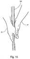
- a thumb of the first hand 27 may be covered by the second hand 29 or situated atop the second hand 29 after the second hand 29 is wrapped around the shaft, as illustrated in Figs. 15 and 18.
- the golfer 25 may address the golf ball 35, as shown in Fig. 1, and prepare for swinging the golf club 75.
- FIG. 19 Another embodiment of the method described above is shown in Fig. 19, wherein the shaft 165 is positioned between fingers of the first hand 27 and of the second hand 29.
- the first and second hands 27, 29 may either utilize the same rectangular cross-sectional area 185b (illustrated in Fig. 19), or different rectangular cross-sectional areas 185b.
- the first and second hands 27, 29 are closed about the shaft 165, completing the gripping method.
- FIG. 20 Another embodiment of the method of gripping a golf club is illustrated in Figs. 20 and 21, wherein the first hand 27 is positioned as discussed above and illustrated in Figs. 13-18.
- the second hand 29 is closed about the shaft 165 at a position spaced apart from the first hand 27.
- the second hand 29 is positioned intermediate the first hand 27 and the top end 67 of the shaft 165.
- FIG. 22-24 A feature of the method as described above is illustrated in Figs. 22-24, wherein any of the above grips is employed with a conventional golf club (shown in Fig. 7).
Abstract
An improved golf club shaft (65,165) comprising a plurality of alternating circular (165a) and
rectangular (165b) cross-sections extending from a top end of the shaft toward a club head and a
corresponding grip (185) which closely follows the alternating cross-sectional contour of the
shaft. The rectangular cross-sections allow the shaft of the golf club to fit between
chosen fingers on either hand of a golfer, thus stiffening the golfer's grip on the club
without creating additional tension in the golfer's arms, which can cause extraneous
motion. Improved golf club shaft grips, employing the alternating cross-sectional area
system as disclosed for the improved shaft are attachable to conventional golf club shafts
for a golfer's use. An improved method for holding a golf club, conventional or as taught
herein, to provide additional stability to a golfer during a golf swing is also taught.
Description
- The present invention relates to an improved golf club shaft and grip and an improved method of gripping a golf club.
- Golf is a recreational and competitive sport that is a popular with large numbers of people of all ages. One of the skills necessary to play the sport well is the ability to maintain control of the golf club before, during, and after swinging the club to contact the golf ball. This skill is particularly important when putting. Many golfers, however, struggle to maintain the proper attitude of the golf club during the swing when using a conventional grip. Thus, the golf club strikes the golf ball at an incorrect angle, causing the golf ball to travel in an undesirable direction.
- Attempts to prevent such extraneous motion of a golf club during a golf swing have included wrist braces intended to prevent movement of the wrist, thereby preventing corresponding movement of the golf club.
- For putters, in particular, various means to better control the golf club during a golf swing have been put forth. For example, U.S. Patent No. 3,679,207, discloses the construction of a golf putter that allows the golfer to use a type of croquet stance instead of the conventional golf stance. The shaft of the patented club is considerably longer than a conventional putter and is used by gripping the club at the end of the shaft with one hand while gripping the shaft at the center of balance with the other hand, thus creating a type of fulcrum effect to prevent extraneous motion of the club. Other inventions, such as U.S. Patent Nos. 4,592,552, and D201,250, disclose extending the shaft of a golf club above a central grip, resulting in the club having approximately the same weight above as below the grip position. Such counter-weighting is also thought to control extraneous motion of the club during a swing.
- While these approaches may be effective, they do not address a very important aspect of controlling extraneous motion of a golf club being swung: the manner in which the golf club is gripped by a golfer. There is a desire, then, for a golf club providing an improved grip and method for gripping a golf club that controls such undesired motion.
- The improved golf club shaft and grip and method for gripping a golf club of the present invention proposes to provide golfer with golf club having a club head attached to a shaft via a hosel, wherein the shaft comprises a plurality of alternating circular and rectangular cross-sections extending from the top end of the shaft (opposite the hosel). A grip covering a portion of the shaft, closely follows the alternating cross-sectional contour of the shaft. The rectangular cross-sections allow the shaft of the golf club to fit between chosen fingers on either hand of a golfer, thus stiffening the golfer's grip on the club without creating additional tension in the golfer's arms, which can cause extraneous motion. Further, such a grip allows the golfer's wrists to remain aligned with the hands, again providing a more controlled grip and, subsequently, swing of the golf club.
- The present invention also provides different grip configurations that can be mounted on conventional golf club shafts. These grip configurations provide various locations at which a golfer may grip the golf club shaft during a golf swing.
- The present invention also teaches a method for holding a golf club on which a preferred embodiment of the shaft and/or grip are used, the method providing additional stability during the swing.
- Further features, embodiments, and advantages of the present invention will become apparent from the following detailed description with reference to the drawings, wherein:
- Fig. 1 is a perspective view of a golf club according to one of the preferred embodiments of the present invention, illustrating a golfer with the golf club in preparation of swinging the golf club;
- Fig. 2 is a side elevation illustrating the shape of a preferred embodiment of the golf club shaft and grip;
- Fig. 3 is a magnification of an area of Fig. 2, illustrating the transition between club shaft and grip profiles;
- Fig. 4 is a cross-section of the golf club of Fig. 2, taken along the line 4-4, illustrating one profile of the club shaft and grip;
- Fig. 5 is a cross-section of the golf club of Fig. 2, taken along the line 5-5, illustrating a second profile of the club shaft and grip;
- Fig. 6 is a front elevation of the golf club of Fig. 2, illustrating the profiles of the club shaft and grip;
- Fig. 7 is a side elevation, illustrating a golf club having conventional shaft and grip profiles;
- Fig. 8 shows a golf club shaft similar to that in Fig. 7, illustrating an embodiment of a grip of the present invention surrounding the club shaft;
- Fig. 9 shows a golf club shaft similar to that in Fig. 7, illustrating another embodiment of a grip of the present invention surrounding the club shaft;
- Fig. 10 shows a golf club shaft similar to that in Fig. 7, illustrating another embodiment of a grip of the present invention surrounding the club shaft;
- Fig. 11 shows a golf club shaft similar to that in Fig. 7, illustrating another embodiment of a grip of the present invention surrounding the club shaft;
- Fig. 12 shows a golf club shaft similar to that in Fig. 7, illustrating another embodiment of a grip of the present invention surrounding the club shaft;
- Figs. 13-16 are a series of partial perspective views of a golf club shaft according to one of the preferred embodiments of the present invention, illustrating a method of gripping a golf club shaft according to one of the preferred embodiments of the present invention;
- Fig. 17 shows a golf club shaft similar to that in Fig. 13, illustrating another embodiment of a method a gripping a golf club shaft;
- Fig. 18 shows a golf club shaft similar to that in Fig. 13, illustrating another embodiment of a method a gripping a golf club shaft;
- Fig. 19 shows a golf club shaft similar to that in Fig. 13, illustrating another embodiment of a method a gripping a golf club shaft;
- Figs. 20-21 are a series of partial perspective views of a golf club shaft according to one of the preferred embodiments of the present invention, illustrating a method of gripping a golf club shaft according to one of the preferred embodiments of the present invention;
- Figs. 22-24 are a series of partial perspective views of a conventional golf club shaft, illustrating a method of gripping a golf club shaft according to one of the preferred embodiments of the present invention; and
- Fig. 25 is a cross-section of the golf club similar to that in Fig. 5, illustrating placement of fingers about a golf club shaft using a method of gripping a golf club shaft according to one of the preferred embodiments of the present invention.
- Referring now to the drawings, wherein like components are identified by similar numbers, a preferred embodiment of the improved golf club shaft and grip are shown in Figures 1-12. As illustrated in Fig. 7, a
typical golf club 75 comprises ahead 45, ahosel 55 and ashaft 65. Theshaft 65 has atop end 67 and abottom end 69. Thebottom end 69 of theshaft 65 is attached to thehosel 55. Theclub head 45 is attached to thehosel 55 opposite theshaft 65. Agrip 85 surrounds a portion of theshaft 65, generally starting at thetop end 67 of theshaft 65 and extending along theshaft 65 to a position intermediate thetop end 67 and thebottom end 69 of theshaft 65. As shown in Fig. 1, agolfer 25 typically holds thegolf club 75 by grasping thegolf club 75 at thegrip 185. - The
club shaft 165 shown in Figures 1-6 comprises three parts: an upper part U, a lower part B and a middle part M intermediate that upper and lower parts U, B. The upper and lower parts U, B comprise cylinders having circular cross-sections of a defined and uniform diameter. The middle part M of theshaft 165 comprises a plurality of alternating rectangular 165b and circular 165a and cross-sectional areas. Thecircular cross-sections 165a are uniformly cylindrical and have the same diameter as that of the upper and lower parts U, B of theshaft 165. Therectangular cross-sections 165b have a length L, a width W and a height H. As seen in Figures 4 and 5, the length L of therectangular cross-sections 165b is approximately the same as the diameter of thecircular cross-sections 165a. The width W of therectangular cross-sections 165b is less than the length L. Further, the width W and the height H of therectangular cross-sections 165b are of a size to allow a golfer to easily position therectangular cross-sections 165b between two fingers, as shown in Fig. 25. Thegrip 185 covers the upper part U, the middle part M, and a portion of the lower part B of theshaft 165, as shown in Figures 2-6. Within the middle part M of theshaft 165, thegrip 185 has a convex profile relative to thecircular cross-sectional areas 165a. Such a profile allows the portions of thegrip 185 covering thecircular cross-sectional areas 165a in the middle part M of theshaft 165 to have the same outer diameter as the portions of thegrip 185 covering the upper part U and the portion of the lower part B, hence providing a familiar gripping area for the golfer. As illustrated in Figs. 4 and 5, the portions of thegrip 185 covering therectangular cross-sectional areas 165b of the middle part M of theshaft 165 are less dense than those portions of thegrip 185 covering thecircular cross-sectional areas 165a. This lack of density provides a level of comfort and security to the golfer without impeding the placement of therectangular cross-sectional areas 165b between two fingers of the golfer's hand, as shown in Fig. 25. - In a preferred embodiment, transitions between the
circular cross-sectional areas 165a and therectangular cross-sectional areas 165b of the middle part M and the transitions between the upper U and lower B parts with the middle part M may be conical shaped to prevent excessive wear or abrasion at the transitions. - Fig. 7, as discussed above, illustrates and
typical golf club 75 with ashaft 65 andgrip 85. In other preferred embodiments, as illustrated in Figs. 8-11, the shaft 65 (as shown in Fig. 7) maintains a uniform, cylindrical, shape from thetop end 67 to thebottom end 69 while thegrip 85 changes contour. In Figs. 8-11, thegrip first part second part first parts grip golf club 75, as shown in Fig. 7. Thesecond parts grip - As shown in Fig. 8, the
first part 287 of thegrip 285 covers theshaft 65 starting at thetop end 67 and extending to abut thesecond part 289 of thegrip 285. Thesecond part 289 of thegrip 285 extends between the abuttingfirst part 287 and thebottom end 69 of theshaft 65. Thesecond part 289 of the grip is convex. - Figs. 9 and 10 illustrate
grips 385, 485 in which thesecond parts 389, 489 each has aconventional portion portion conventional portion 389a of thesecond part 389 is located intermediate thefirst part 387 of thegrip 385 and the protrudingportion 389b of thesecond part 389 of thegrip 385. The protrudingportion 389b surrounds theshaft 65 in a uniform, geometric shape. In Fig. 9, the protrudingportion 389b resembles a vertical hexagonal. - In Fig. 10, the protruding
portion 489b is intermediate theconventional portion 489a of the second part 489 and thefirst part 487 of the grip 485. The protrudingportion 489b surrounds theshaft 65 in a uniform, geometric shape. In Fig. 10, the protrudingportion 489b is convex. - As shown in Fig. 11, the
second part 589b of thegrip 585 may include multiple contours. Thefirst part 587 of thegrip 585 extends from thetop end 67 of theshaft 65 to abutting proximity to the second part 589. The second part 589 extends from a terminus of thefirst part 587 toward thebottom end 69 of theshaft 65. The second part comprises protrudingportions 589b connected by a shortconventional portion 589a. The protrudingportions 589b may be the same or different shapes. In Fig. 11, the protrudingportions 589b are the same shape. Further, the protrudingportions 589b may be of any geometric shape. In Fig. 11, the protrudingportions 589b are barrel shaped. - Fig. 12 illustrates a preferred embodiment combining elements of the contoured
golf club shaft 665 as shown in Figs. 1-6, and of the contouredgrip 685, as shown in Fig. 8. Theshaft 665 comprises three sections: an upper section U and a lower section B, both of which have a conventionally cylindrical shape; and a middle section M intermediate the upper and lower sections U, B of theshaft 665. The middle section M of is cylindrically shaped with a circular cross-section having a diameter between about 0.25 and 0.5 that of the diameter of the upper and lower sections U, B. Transitions between the sections may be abrupt or gradual. As illustrated in Fig. 12, the transition between the upper section U and the middle section M is substantially an abrupt, square-edged demarcation, while the transition between the middle section M and the lower section B is a gradual, conically shaped transition. Thegrip 685 comprises afirst part 687 and asecond part 689. Thefirst part 687 comprises a contour similar to a conventional grip of agolf club 75, as shown in Fig. 7. Thesecond part 689 of thegrip 685 comprises at least one contoured area having a profile different than that of a conventional grip. As shown in Fig. 12, thefirst part 687 of thegrip 685 covers theshaft 665 starting at the top end 667 and extending to abutting engagement with thesecond part 689. Thesecond part 689 of thegrip 685 extends between the abuttingfirst part 687 and the bottom end 669 of theshaft 665. Thesecond part 689 of thegrip 665 may have any geometric shape. Thesecond part 689 of thegrip 665 shown in Fig. 12 is convex. - Figs. 13-18 illustrate a preferred method for gripping the
golf club 75 shown in Figs. 1-6. Thegolfer 25 first positions thegolf club 75 with thehead 45 of thegolf club 75 adjacent to a striking surface (e.g., a greens area on a golf course) and agolf ball 35 and perpendicular to thegolfer 25, as shown in Fig. 1. Thegolfer 25 positions afirst hand 27 in proximity to thegolf club 75, fingers of thefirst hand 27 oriented toward one of the rectangularcross-sectional areas 165b of the shaft covered by and identified by thecorresponding grip 185b, as illustrated in Fig. 13. The golfer then inserts the rectangularcross-sectional area 185b of theshaft 165 between two fingers of thefirst hand 27, as illustrated in Figs. 14 and 25. As shown in Figs. 14, 16 and 17, the rectangularcross-sectional area 185b of theshaft 165 is insertable between any two fingers of the first hand: between index and middle fingers (Fig. 14); between middle and ring fingers (Fig. 16); and between ring and little fingers (Fig. 17). - Once the
shaft 165 is properly positioned between fingers of thefirst hand 27, the fingers of the first hand are closed about theshaft 165, enclosing theshaft 165 within a fist made of thefirst hand 27, as shown in Fig. 14. Fingers of asecond hand 29 are wrapped around theshaft 165, at least partially overlapping thefirst hand 27. A thumb of thefirst hand 27 may be covered by thesecond hand 29 or situated atop thesecond hand 29 after thesecond hand 29 is wrapped around the shaft, as illustrated in Figs. 15 and 18. Once the first andsecond hands golfer 25 may address thegolf ball 35, as shown in Fig. 1, and prepare for swinging thegolf club 75. - Another embodiment of the method described above is shown in Fig. 19, wherein the
shaft 165 is positioned between fingers of thefirst hand 27 and of thesecond hand 29. The first andsecond hands cross-sectional area 185b (illustrated in Fig. 19), or different rectangularcross-sectional areas 185b. After properly positioning the shaft between fingers of both hands, the first andsecond hands shaft 165, completing the gripping method. - Another embodiment of the method of gripping a golf club is illustrated in Figs. 20 and 21, wherein the
first hand 27 is positioned as discussed above and illustrated in Figs. 13-18. Thesecond hand 29 is closed about theshaft 165 at a position spaced apart from thefirst hand 27. Preferably, thesecond hand 29 is positioned intermediate thefirst hand 27 and thetop end 67 of theshaft 165. - A feature of the method as described above is illustrated in Figs. 22-24, wherein any of the above grips is employed with a conventional golf club (shown in Fig. 7).
- It will therefore be readily understood by those persons skilled in the art that the present invention is susceptible of broad utility and application. Many embodiments and adaptations of the present invention other than those herein described, as well as many variations, modifications and equivalent arrangements, will be apparent from or reasonably suggested by the present invention and the foregoing description thereof, without departing from the substance or scope of the present invention. Accordingly, while the present invention has been described herein in detail in relation to its preferred embodiment, it is to be understood that this disclosure is only illustrative and exemplary of the present invention and is made merely for purposes of providing a full and enabling disclosure of the invention. The foregoing disclosure is not intended or to be construed to limit the present invention or otherwise to exclude any such other embodiments, adaptations, variations, modifications and equivalent arrangements, the present invention being limited only by the claims appended hereto and the equivalents thereof.
Claims (43)
- A golf club having a club head attached to a shaft via a hosel, the shaft having a top end and a bottom end, the bottom end being attachable to the hosel, the shaft comprising:an upper section, a lower section and a middle section intermediate the upper and lower sections, the upper section extending from the top end of the shaft to one end of the middle section, the lower section extending from the bottom end of the shaft to an end of the middle section opposite the upper section, the upper and lower sections having circular cross-sections approximating a conventional golf club shaft, the middle section of the shaft having a plurality of alternating rectangular and circular cross-sections extending therethrough, the circular cross sections approximating the cross sections of the upper and lower sections of the shaft, the rectangular cross-sections having a length, a width, and a height, the length of the rectangular cross sections being greater that the width, the width and height of the rectangular cross sections being sufficient to insert said rectangular cross sections between fingers of at least one hand of a golfer, and wherein the length of the rectangular cross sections is approximately the same as a diameter of the circular cross-sections of the middle section, anda grip adjacent to and surrounding a portion of the shaft, the grip having a first grip portion extending from the top end of the shaft to the middle section of the shaft, a second grip portion extending over the middle section, and a third grip portion cover a part of the lower section extending from the middle portion toward the bottom end of the shaft, the first grip portion having a generally cylindrical cross-section, the second portion of the grip comprising corresponding alternating rectangular and circular cross sections, the circular cross sections being convex along each length of the circular cross sections of the shaft, the rectangular cross sections of the grip corresponding to the rectangular cross sections of the shaft, and the third portion of the grip being convex relative to the lower section of the shaft.
- A golf club according to claim 1, wherein the rectangular cross sections of the grip corresponding to the rectangular cross sections of the shaft are positioned such that the length of the cross sections are oriented perpendicular to the club head.
- A golf club according to claim 1, wherein the diameter of the convex shaped portions of the grip is greater than the length of the rectangular cross sections of the grip.
- A golf club according to claim 1, wherein the width and the height of the rectangular cross sections of the grip and shaft are of a sufficient size for a golfer to position at least one finger along each length of at least one of the rectangular cross sections of the grip and shaft.
- On a golf club having a head attached to a bottom end of a shaft, the shaft having a top end opposite the bottom end, a grip comprising a tube extending from the top end of the shaft toward a terminating position intermediate the top and bottom ends of the shaft, the tube having an inner diameter sufficiently sized to insert the shaft therethrough, the tube also having a first end proximate to the top end of the shaft and a second end at the terminating position, the grip further comprising an outer surface having a contoured area, said contour being relative to a longitudinal axis of the grip intermediate the first and second ends.
- The grip according to claim 5, wherein the outer surface comprises a first contour section and a second contour section, the first contour section extending from the first end of the grip to a transition point between the first and second contour sections, the second contour section extending from the transition point to the second end of the grip.
- The grip according to claim 6, wherein the first contour section of the outer surface is cylindrical.
- The grip according to claim 7, wherein the second contour section of the outer surface is an extension of the first contour section of the outer surface.
- The grip according to claim 7, wherein the second contour section of the outer surface is convex.
- The grip according to claim 7, wherein the second contour section of the outer surface has a first part and a second part, the first part extending from the transition point and the second part extending from the first part to the second end of the grip, the first part having an outer surface contour approximating the first contour section of the grip, the second part having a geometric shape with an outer diameter greater than an outer diameter of the first part.
- The grip according to claim 7, wherein the second contour section of the outer surface has a first part and a second part, the first part extending from the transition point and the second part extending from the first part to the second end of the grip, the first part being convex, the second part approximating the first contour section of the grip.
- The grip according to claim 7, wherein the second contour section of the outer surface has a first part, a second part and a third part, the first part extending from the transition point to the second part, the second portion extending to the third part, and the third part extending to the second end of the grip, the first and third parts being convex with a defined diameter, the second part approximating the first contour section of the grip.
- The grip according to claim 12, wherein the second part of the second contour section of the grip has an outer diameter sufficiently sized such that the second part is insertable between fingers of a golfer for establishing a hold on the golf club.
- A method of gripping a golf club, said club having a head attached to one end of a shaft, the head generally perpendicular to the shaft, the shaft having a longitudinal axis extending upwardly from the head to a top end of the shaft, the shaft manipulatable by a golfer, the method comprising the steps:orienting a controlling hand perpendicular to the longitudinal axis of the shaft and perpendicular to the head;placing the shaft between two fingers of the controlling hand;closing the controlling hand about the shaft, the shaft resting upon a portion of the controlling hand opposite the fingers; andencircling the shaft with a guiding hand, the thumb of the guiding hand parallel to the longitudinal axis of the shaft, the guiding hand in vertical relationship to the controlling hand relative to the longitudinal axis of the shaft.
- The method according to claim 14, wherein the golfer has a left hand and a right hand, the left hand of the golfer being the controlling hand and the right hand of the golfer being the guiding hand.
- The method according to claim 14, wherein the golfer has a right hand and a left hand, the right hand of the golfer being the controlling hand and the left hand of the golfer being the guiding hand.
- The method according to claim 14, wherein the locating step comprises placing the shaft between an index finger and a middle finger of the controlling hand.
- The method according to claim 14, wherein the locating step comprises placing the shaft between a middle finger and a ring finger of the controlling hand.
- The method according to claim 14, wherein the locating step comprises placing the shaft between a ring finger and a little finger of the controlling hand.
- The method according to claim 14, wherein the encircling step comprises placing the guidance hand on the shaft intermediate the controlling hand and the top end of the shaft.
- The method according to claim 14, wherein the encircling step comprises placing the guidance hand on the shaft intermediate the controlling hand and the head of the club.
- The method according to claim 14, wherein the enclosing step further comprises extending at least one finger of the guidance hand parallel to the longitudinal axis of the shaft.
- The method according to claim 22, wherein the at least one finger comprises an index finger.
- A method of gripping a golf club, said club having a head attached to one end of a shaft, the head generally perpendicular to the shaft, the shaft having a longitudinal axis extending upwardly from the head to a top end, the shaft manipulatable by a golfer, the method comprising the steps:orienting a controlling hand parallel to the longitudinal axis of the shaft and oriented in the direction of the head such that the shaft is intermediate the controlling hand and the head;placing the shaft between two fingers of the controlling hand;closing the controlling hand about the shaft, the shaft resting upon a palm of the controlling hand; andencircling the shaft with a guidance hand, a thumb of the guidance hand parallel to the longitudinal axis of the shaft and oriented toward the head of the club, the guidance hand in vertical relationship to the controlling hand relative to the longitudinal axis of the shaft.
- The method according to claim 24, wherein the golfer has a left hand and a right hand, the left hand of the golfer being the controlling hand and the right hand of the golfer being the guidance hand.
- The method according to claim 24, wherein the golfer has a right hand and a left hand, the right hand of the golfer being the controlling hand and the left hand of the golfer being the guidance hand.
- The method according to claim 24, wherein the locating step comprises placing the shaft between an index finger and a middle finger of the controlling hand.
- The method according to claim 24, wherein the locating step comprises placing the shaft between a middle finger and a ring finger of the controlling hand.
- The method according to claim 24, wherein the locating step comprises placing the shaft between a ring finger and a little finger of the controlling hand.
- The method according to claim 24, wherein the encircling step comprises placing the guidance hand on the shaft intermediate the controlling hand and the top end of the shaft.
- The method according to claim 24, wherein the encircling step comprises placing the guidance hand on the shaft intermediate the controlling hand and the head of the golf club.
- The method according to claim 24, wherein the enclosing step further comprises extending at least one finger of the guidance hand parallel to the longitudinal axis of the shaft.
- The method according to claim 32, wherein the at least one finger comprises an index finger.
- A method of gripping a golf club, said club having a head attached to one end of a shaft, the head generally perpendicular to the shaft, the shaft having a longitudinal axis extending upwardly from the head to a top end, the shaft being manipulated by a golfer, the method comprising the steps:wherein the guidance hand is in vertical relationship to the controlling hand relative to the longitudinal axis of the shaft.orienting a controlling hand perpendicular to the longitudinal axis of the shaft and perpendicular to the head;placing the shaft between two fingers of the controlling hand;closing the controlling hand about the shaft, the shaft resting upon a portion of the controlling hand opposite the fingers;orienting a guidance hand parallel to the controlling hand orientation relative to the shaft;placing the shaft between two fingers of the guidance hand; andclosing the guidance hand about the shaft, a thumb of the guidance hand parallel to the longitudinal axis of the shaft,
- The method according to claim 34, wherein the golfer has a right hand and a left hand, the left hand of the golfer being the controlling hand and the right hand of the golfer being the guidance hand.
- The method according to claim 34, wherein the golfer has a right hand and a left hand, the right hand of the golfer being the controlling hand and the left hand of the golfer being the guiding hand.
- The method according to claim 34, wherein the locating step comprises placing the shaft between an index finger and a middle finger of the controlling hand.
- The method according to claim 34, wherein the locating step comprises placing the shaft between a middle finger and a ring finger of the controlling hand.
- The method according to claim 34, wherein the locating step comprises placing the shaft between a ring finger and a little finger of the controlling hand.
- The method according to claim 34, wherein the encircling step comprises placing the guidance hand on the shaft intermediate the controlling hand and the top end of the shaft.
- The method according to claim 34, wherein the encircling step comprises placing the guidance hand on the shaft intermediate the controlling hand and the head of the club..
- The method according to claim 34, wherein the enclosing step further comprises extending at least one finger of the guidance hand parallel to the longitudinal axis of the shaft.
- The method according to claim 42, wherein the at least one finger comprises an index finger.
Applications Claiming Priority (2)
| Application Number | Priority Date | Filing Date | Title |
|---|---|---|---|
| US10/375,878 US20040166956A1 (en) | 2003-02-26 | 2003-02-26 | Golf club shaft and grip and method for gripping golf club |
| US375878 | 2003-02-26 |
Publications (1)
| Publication Number | Publication Date |
|---|---|
| EP1452208A1 true EP1452208A1 (en) | 2004-09-01 |
Family
ID=32771474
Family Applications (1)
| Application Number | Title | Priority Date | Filing Date |
|---|---|---|---|
| EP04001269A Withdrawn EP1452208A1 (en) | 2003-02-26 | 2004-01-22 | Improved golf club shaft and grip and method for gripping golf club |
Country Status (6)
| Country | Link |
|---|---|
| US (2) | US20040166956A1 (en) |
| EP (1) | EP1452208A1 (en) |
| JP (1) | JP2004255179A (en) |
| KR (1) | KR20040076594A (en) |
| AU (1) | AU2004200596A1 (en) |
| CA (1) | CA2456264A1 (en) |
Cited By (6)
| Publication number | Priority date | Publication date | Assignee | Title |
|---|---|---|---|---|
| WO2009144323A2 (en) * | 2008-05-30 | 2009-12-03 | Mccarthy, Denis Alexis | Golf club grip |
| US7637821B2 (en) | 2007-09-24 | 2009-12-29 | Johnson Lanny L | Visual and tactile confirmation golf grip and system |
| US8062147B2 (en) | 2007-09-24 | 2011-11-22 | Johnson Lanny L | Visual and tactile confirmation golf grip and system |
| US9011279B2 (en) | 2012-02-21 | 2015-04-21 | Lanny L. Johnson | Throwing dart |
| US9982963B2 (en) | 2012-02-21 | 2018-05-29 | Lanny L. Johnson | Firearm having tactile biofeedback reference feature |
| US10371481B2 (en) | 2012-02-21 | 2019-08-06 | Lanny L. Johnson | Tactile biofeedback reference attachment |
Families Citing this family (7)
| Publication number | Priority date | Publication date | Assignee | Title |
|---|---|---|---|---|
| US7261652B2 (en) * | 2004-01-30 | 2007-08-28 | Thomas Robert Gold | Method of holding a putter and putting a golf ball |
| CA2628037A1 (en) * | 2005-10-25 | 2007-05-03 | Ettore Casati, Jr. | Golf club grip and method of using same |
| US20070123365A1 (en) * | 2005-11-30 | 2007-05-31 | Ferris Richard D | Golf club grip |
| KR101621468B1 (en) * | 2014-01-21 | 2016-05-16 | 박광영 | Look Watching Side Swing Putter |
| KR101539551B1 (en) * | 2015-05-12 | 2015-07-29 | 박성욱 | Grip for Golf Club |
| KR20180000822U (en) | 2016-09-13 | 2018-03-21 | (주)셀트리온 | Cosmetinc container having an impregnating material for cosmetic compostion |
| US20220111273A1 (en) * | 2020-10-09 | 2022-04-14 | Josh Aiello | Sports training device |
Citations (4)
| Publication number | Priority date | Publication date | Assignee | Title |
|---|---|---|---|---|
| US1618640A (en) * | 1926-06-01 | 1927-02-22 | Sterling W Dawson | Golf club |
| US2298505A (en) * | 1941-02-10 | 1942-10-13 | Raymond E Ottman | Handle for golf clubs |
| US2321773A (en) * | 1941-11-13 | 1943-06-15 | Ruemelin Richard | Golfer's putter |
| US3173689A (en) * | 1962-02-05 | 1965-03-16 | Michael D Serblin | Golf club handle |
Family Cites Families (8)
| Publication number | Priority date | Publication date | Assignee | Title |
|---|---|---|---|---|
| US201250A (en) * | 1878-03-12 | Improvement in tanks for stock-cars | ||
| US1210182A (en) * | 1916-06-24 | 1916-12-26 | Patrick H Lynch | Golf-club. |
| US2132219A (en) * | 1937-06-19 | 1938-10-04 | Pirie John | Golf club |
| US3679207A (en) * | 1970-08-03 | 1972-07-25 | Raymond J Florian | Golf putter construction |
| US4592552A (en) * | 1985-01-30 | 1986-06-03 | Garber Robert L | Golf club putter |
| US4600195A (en) * | 1985-03-11 | 1986-07-15 | Hunter James J | Weighted golf club handle |
| US5632691A (en) * | 1995-03-31 | 1997-05-27 | Golfology, Inc. | Golf putter |
| US5749792A (en) * | 1996-08-30 | 1998-05-12 | Engfer; Jeffrey R. | Golf club handle oversize grip kit |
-
2003
- 2003-02-26 US US10/375,878 patent/US20040166956A1/en not_active Abandoned
-
2004
- 2004-01-22 EP EP04001269A patent/EP1452208A1/en not_active Withdrawn
- 2004-01-26 CA CA002456264A patent/CA2456264A1/en not_active Abandoned
- 2004-02-12 KR KR1020040009367A patent/KR20040076594A/en not_active Application Discontinuation
- 2004-02-12 JP JP2004034956A patent/JP2004255179A/en active Pending
- 2004-02-16 AU AU2004200596A patent/AU2004200596A1/en not_active Abandoned
- 2004-12-23 US US11/021,605 patent/US20050107181A1/en not_active Abandoned
Patent Citations (4)
| Publication number | Priority date | Publication date | Assignee | Title |
|---|---|---|---|---|
| US1618640A (en) * | 1926-06-01 | 1927-02-22 | Sterling W Dawson | Golf club |
| US2298505A (en) * | 1941-02-10 | 1942-10-13 | Raymond E Ottman | Handle for golf clubs |
| US2321773A (en) * | 1941-11-13 | 1943-06-15 | Ruemelin Richard | Golfer's putter |
| US3173689A (en) * | 1962-02-05 | 1965-03-16 | Michael D Serblin | Golf club handle |
Cited By (11)
| Publication number | Priority date | Publication date | Assignee | Title |
|---|---|---|---|---|
| US7637821B2 (en) | 2007-09-24 | 2009-12-29 | Johnson Lanny L | Visual and tactile confirmation golf grip and system |
| US7794332B2 (en) | 2007-09-24 | 2010-09-14 | Johnson Lanny L | Visual and tactile confirmation golf grip and system |
| US8062147B2 (en) | 2007-09-24 | 2011-11-22 | Johnson Lanny L | Visual and tactile confirmation golf grip and system |
| US8092317B2 (en) | 2007-09-24 | 2012-01-10 | Lanny L Johnson | Visual and tactile confirmation golf grip and system |
| WO2009144323A2 (en) * | 2008-05-30 | 2009-12-03 | Mccarthy, Denis Alexis | Golf club grip |
| WO2009144323A3 (en) * | 2008-05-30 | 2010-01-14 | Mccarthy, Denis Alexis | Golf club grip |
| US9011279B2 (en) | 2012-02-21 | 2015-04-21 | Lanny L. Johnson | Throwing dart |
| US9982963B2 (en) | 2012-02-21 | 2018-05-29 | Lanny L. Johnson | Firearm having tactile biofeedback reference feature |
| US10077967B1 (en) | 2012-02-21 | 2018-09-18 | Lanny L. Johnson | Tactile biofeedback reference attachment |
| US10197357B2 (en) | 2012-02-21 | 2019-02-05 | Lanny L. Johnson | Tactile biofeedback reference attachment |
| US10371481B2 (en) | 2012-02-21 | 2019-08-06 | Lanny L. Johnson | Tactile biofeedback reference attachment |
Also Published As
| Publication number | Publication date |
|---|---|
| US20040166956A1 (en) | 2004-08-26 |
| CA2456264A1 (en) | 2004-08-26 |
| US20050107181A1 (en) | 2005-05-19 |
| AU2004200596A1 (en) | 2004-09-16 |
| KR20040076594A (en) | 2004-09-01 |
| JP2004255179A (en) | 2004-09-16 |
Similar Documents
| Publication | Publication Date | Title |
|---|---|---|
| US6022278A (en) | Golf club, grip, and club positioning method | |
| US5518235A (en) | Golf club head | |
| US4848746A (en) | Tennis racket grip | |
| EP1452208A1 (en) | Improved golf club shaft and grip and method for gripping golf club | |
| US6916260B1 (en) | Tennis racket grip device | |
| US5169152A (en) | Golf club grip | |
| US6190266B1 (en) | Golf putter | |
| US20110275458A1 (en) | Batting Skills Development Device | |
| US6213891B1 (en) | Golf club grip and method of putting | |
| US6296577B1 (en) | Method of putting a golf ball | |
| US6786835B1 (en) | Putter grip and method | |
| US7357729B2 (en) | Golf club | |
| US5679080A (en) | Golf club swing training device | |
| WO2001051134A3 (en) | Golf clubs intended for use in putting | |
| US5143375A (en) | Golf club finger support device | |
| US20040018888A1 (en) | Alternative golf club and method of using the same | |
| US4399993A (en) | Two handed tennis racket | |
| ZA200406921B (en) | Engineered baculoviruses and their use | |
| JP2002506702A (en) | Grip for hand-held sports equipment | |
| US20200238140A1 (en) | Golf Club Grip | |
| US4752070A (en) | Teaching aid device for racket sports | |
| US20050026715A1 (en) | Golf putter head | |
| US5556345A (en) | Golf club with improved shafts | |
| US20070123365A1 (en) | Golf club grip | |
| WO1998050115A1 (en) | Golf club |
Legal Events
| Date | Code | Title | Description |
|---|---|---|---|
| PUAI | Public reference made under article 153(3) epc to a published international application that has entered the european phase |
Free format text: ORIGINAL CODE: 0009012 |
|
| AK | Designated contracting states |
Kind code of ref document: A1 Designated state(s): AT BE BG CH CY CZ DE DK EE ES FI FR GB GR HU IE IT LI LU MC NL PT RO SE SI SK TR |
|
| AX | Request for extension of the european patent |
Extension state: AL LT LV MK |
|
| AKX | Designation fees paid | ||
| REG | Reference to a national code |
Ref country code: DE Ref legal event code: 8566 |
|
| STAA | Information on the status of an ep patent application or granted ep patent |
Free format text: STATUS: THE APPLICATION IS DEEMED TO BE WITHDRAWN |
|
| 18D | Application deemed to be withdrawn |
Effective date: 20050302 |