EP1452119A1 - Electric vacuum cleaner - Google Patents
Electric vacuum cleaner Download PDFInfo
- Publication number
- EP1452119A1 EP1452119A1 EP04001713A EP04001713A EP1452119A1 EP 1452119 A1 EP1452119 A1 EP 1452119A1 EP 04001713 A EP04001713 A EP 04001713A EP 04001713 A EP04001713 A EP 04001713A EP 1452119 A1 EP1452119 A1 EP 1452119A1
- Authority
- EP
- European Patent Office
- Prior art keywords
- main body
- vacuum cleaner
- cleaner main
- grip portion
- suction tool
- Prior art date
- Legal status (The legal status is an assumption and is not a legal conclusion. Google has not performed a legal analysis and makes no representation as to the accuracy of the status listed.)
- Withdrawn
Links
- 239000000428 dust Substances 0.000 claims abstract description 17
- 238000012856 packing Methods 0.000 claims description 7
- 238000004140 cleaning Methods 0.000 abstract description 20
- 230000002093 peripheral effect Effects 0.000 description 3
- 230000002787 reinforcement Effects 0.000 description 1
- 229920003002 synthetic resin Polymers 0.000 description 1
- 239000000057 synthetic resin Substances 0.000 description 1
Images







Classifications
-
- A—HUMAN NECESSITIES
- A47—FURNITURE; DOMESTIC ARTICLES OR APPLIANCES; COFFEE MILLS; SPICE MILLS; SUCTION CLEANERS IN GENERAL
- A47L—DOMESTIC WASHING OR CLEANING; SUCTION CLEANERS IN GENERAL
- A47L9/00—Details or accessories of suction cleaners, e.g. mechanical means for controlling the suction or for effecting pulsating action; Storing devices specially adapted to suction cleaners or parts thereof; Carrying-vehicles specially adapted for suction cleaners
- A47L9/10—Filters; Dust separators; Dust removal; Automatic exchange of filters
- A47L9/12—Dry filters
- A47L9/122—Dry filters flat
-
- H—ELECTRICITY
- H04—ELECTRIC COMMUNICATION TECHNIQUE
- H04M—TELEPHONIC COMMUNICATION
- H04M1/00—Substation equipment, e.g. for use by subscribers
- H04M1/72—Mobile telephones; Cordless telephones, i.e. devices for establishing wireless links to base stations without route selection
- H04M1/725—Cordless telephones
-
- A—HUMAN NECESSITIES
- A47—FURNITURE; DOMESTIC ARTICLES OR APPLIANCES; COFFEE MILLS; SPICE MILLS; SUCTION CLEANERS IN GENERAL
- A47L—DOMESTIC WASHING OR CLEANING; SUCTION CLEANERS IN GENERAL
- A47L5/00—Structural features of suction cleaners
- A47L5/12—Structural features of suction cleaners with power-driven air-pumps or air-compressors, e.g. driven by motor vehicle engine vacuum
- A47L5/22—Structural features of suction cleaners with power-driven air-pumps or air-compressors, e.g. driven by motor vehicle engine vacuum with rotary fans
- A47L5/28—Suction cleaners with handles and nozzles fixed on the casings, e.g. wheeled suction cleaners with steering handle
- A47L5/32—Suction cleaners with handles and nozzles fixed on the casings, e.g. wheeled suction cleaners with steering handle with means for connecting a hose
-
- A—HUMAN NECESSITIES
- A47—FURNITURE; DOMESTIC ARTICLES OR APPLIANCES; COFFEE MILLS; SPICE MILLS; SUCTION CLEANERS IN GENERAL
- A47L—DOMESTIC WASHING OR CLEANING; SUCTION CLEANERS IN GENERAL
- A47L9/00—Details or accessories of suction cleaners, e.g. mechanical means for controlling the suction or for effecting pulsating action; Storing devices specially adapted to suction cleaners or parts thereof; Carrying-vehicles specially adapted for suction cleaners
- A47L9/32—Handles
- A47L9/325—Handles for wheeled suction cleaners with steering handle
-
- A—HUMAN NECESSITIES
- A47—FURNITURE; DOMESTIC ARTICLES OR APPLIANCES; COFFEE MILLS; SPICE MILLS; SUCTION CLEANERS IN GENERAL
- A47L—DOMESTIC WASHING OR CLEANING; SUCTION CLEANERS IN GENERAL
- A47L9/00—Details or accessories of suction cleaners, e.g. mechanical means for controlling the suction or for effecting pulsating action; Storing devices specially adapted to suction cleaners or parts thereof; Carrying-vehicles specially adapted for suction cleaners
- A47L9/32—Handles
- A47L9/327—Handles for suction cleaners with hose between nozzle and casing
-
- A—HUMAN NECESSITIES
- A63—SPORTS; GAMES; AMUSEMENTS
- A63H—TOYS, e.g. TOPS, DOLLS, HOOPS OR BUILDING BLOCKS
- A63H3/00—Dolls
Definitions
- the present invention relates to an electric vacuum cleaner. More particularly, it relates to an upright type electric vacuum cleaner which can perform both, floor cleaning and handy cleaning using an attachment, wherein the electric vacuum cleaner is of simple arrangement which does not require a switching mechanism for switching between a flow path for ordinary use and a flow path for use with an attachment.
- An upright type electric vacuum cleaner which is capable of cleaning not only floors but also places other than floors such as walls, is conventionally known.
- Such an upright type electric vacuum cleaner is provided with two flow paths, namely a main body flow path which extends from a suction tool main body to a dust chamber of a vacuum cleaner main body and a flow path for handy cleaning which extends to the dust chamber (refer to Japanese Unexamined Patent Publication No. 233482/2002).
- a flexible hose which forms the flow path for handy cleaning is in communication with a grip portion connected to an upper part of the vacuum cleaner main body in a freely attachable and detachable manner. For performing handy cleaning, the grip portion can be detached from the vacuum cleaner main body so as to use the same as an attachment for handy cleaning.
- the electric vacuum cleaner as disclosed in the above reference is provided with a flow path opening and closing means for handy cleaning which closes the flow path for handy cleaning in a condition in which the vacuum cleaner main body is inclined for performing floor cleaning while it opens the flow path for handy cleaning in a condition in which the vacuum cleaner main body is uprising, and the overall structure is thus complicated.
- the present invention has been made for solving such a problem, and it is an object thereof to provide an upright type electric vacuum cleaner which can perform both floor cleaning and handy cleaning using an attachment, wherein the electric vacuum cleaner is of simple arrangement which does not require a switching mechanism for switching between a flow path for ordinary use and a flow path for use with the attachment.
- an electric vacuum cleaner including a vacuum cleaner main body, a suction tool main body connected to the vacuum cleaner main body and having an suction inlet which is open at a lower surface thereof, a dust box connected to the vacuum cleaner main body, and a grip portion for operating the vacuum cleaner main body.
- the suction tool main body, an interior of the vacuum cleaner main body, the grip portion and the dust box are directly connected in this order such that circulation of air is permitted, and the interior of the vacuum cleaner main body and the grip portion are connected in a freely attachable and detachable manner.
- a packing is provided at a connecting portion of the flow path between the interior of the vacuum cleaner main body and the grip portion.
- suction tool main body and the interior of the vacuum cleaner main body are connected through a connecting hose and that the connecting hose is connected to the suction tool main body in a freely attachable and detachable manner.
- At least a part of the connecting hose is extensible and that a part of the connecting hose is housed in the interior of the vacuum cleaner main body.
- the upright type electric vacuum cleaner illustrated in Figs. 1 to 6 is composed of a suction tool main body 1, a vacuum cleaner main body 2, a grip portion 3, a tip end side pipe 4 fixedly attached to the grip portion 3, a flexible hose 5, and a rotatable tube 6.
- a tip end portion of the tip end side pipe 4 is inserted into a tubular tip end side pipe supporting portion 7 of the vacuum cleaner main body 2 to be supported thereby in a freely attachable and detachable manner.
- the suction tool main body 1 includes a suction inlet at a lower surface thereof and a rotating brush (not shown) inside of the suction inlet.
- the suction tool main body 1 is communicated with a rear portion 12 of the vacuum cleaner main body 2 through a connecting hose 11.
- An electric air blower 10 is incorporated in the vacuum cleaner main body 2, and a dust box 8 is provided at an upper portion of the vacuum cleaner main body 2.
- the suction tool main body 1 is provided at a lower portion of the vacuum cleaner main body 2 to be freely rotating in front and rear directions through a fulcrum (not shown) which is provided at the vacuum cleaner main body 2.
- the grip portion 3 comprises of a hollow tubular body, and a grip 9 is formed at an upper end thereof.
- the tip end side pipe 4 and the flexible hose 5 are connected through this grip portion 3.
- the grip portion 3 is connected to the tip end side pipe supporting portion 7 in a freely attachable and detachable manner, and it is also connected to the dust box 8 located at an upper portion on a front surface side of the vacuum cleaner main body 2 through the flexible hose 5 which is disposed on a rearward side of the grip portion 3.
- the tip end side pipe 4 is connected to the connecting hose 11 in the interior of the rear portion 12 of the vacuum cleaner main body 2, so that the grip portion 3 is in communication with the suction tool main body 1 through both of the tip end side pipe 4 and the connecting hose 11.
- a packing 13 is provided inside of the rear portion 12 of the vacuum cleaner main body 2 for maintaining an air-tight condition between the rear portion 12 and the grip portion 3 as illustrated in Figs. 5 and 6.
- the connecting hose 11 is connected to a lower portion of the packing 13 through screwing or similar means by utilizing concave and convex portions of the accordion-like connecting hose 11.
- An inner peripheral surface of the packing 13 projects inside in the radial direction so that it might abut an outer peripheral surface of the tip end side pipe 4 of the grip portion 3, and the tip end side pipe 4 might be maintained in an air-tight condition thereby.
- a guide member 14 for guiding the tip end side pipe 4 to the center of the packing 13 is provided above the packing 13.
- the suction tool main body 1, the rear portion 12 of the vacuum cleaner main body 2, the grip portion 3 and the dust box 8 are directly connected in this order such that circulation of air is permitted, and the rear portion 12 of the vacuum cleaner main body 2 and the grip portion 3 are connected in a freely attachable and detachable manner.
- this arrangement it is possible to perform both ordinary use (floor cleaning) using the suction tool main body 1 and use of an attachment through the grip portion 3 by utilizing one successive flow path, so that it is possible to omit a flow path switching mechanism to thereby simplify the structure.
- the grip portion 3 might be used as an attachment so that it is possible to clean ceilings or walls located at high positions.
- the portion between the suction tool main body 1 and the rear portion 12 of the vacuum cleaner main body 2 is connected through the connecting hose 11 as illustrated in Figs. 4 and 6 to 8, and the connecting hose 11 is connected to the suction tool main body 1 in a freely attachable and detachable manner.
- an adapter 11a at an end portion of the connecting hose 11 is inserted into an air inlet 1a of the suction tool main body 1 in a freely attachable and detachable manner. Accordingly, when the connecting hose 11 is drawn out from the suction tool main body 1 to change from the condition of ordinary use of Fig. 4 to the condition of Fig.
- the connecting hose 11 might be used as an attachment, and detailed spots located at lower positions, for instance, doorsills or corners between walls and floors can be easily cleaned. That is, since it is possible to use the connecting hose 11 also as an attachment in the present embodiment, aspects of cleaning can be remarkably enlarged thereby.
- the present embodiment is so arranged that at least a part of the connecting hose 11 is extensible and a part of the connecting hose 11 is housed in the rear portion 12 of the vacuum cleaner main body 2. Accordingly, the connecting hose 11 is extended only by a length which is necessary for connection with the suction tool main body 1 for ordinary use as illustrated in Figs. 4 and 6, while the remaining portion is housed in the rear portion 12 of the vacuum cleaner main body 2 in the shrunk condition so as to improve its external appearance.
- the connecting hose 11 when the connecting hose 11 is to be used as an attachment, the connecting hose 11 shall be drawn out from the rear portion 12 of the vacuum cleaner main body 2 so as to improve the degree of freedom of the swinging movements of the hose. It is accordingly possible to perform cleaning of a broader region using the connecting hose 11.
- connecting hose 11 is extensible so that it might be housed in the rear portion 12, it is also possible that the entire connecting hose 11 is extensible.
- the present embodiment is so arranged that the suction tool main body 1 and the rear portion 12 of the vacuum cleaner main body 2 are connected through the connecting hose 11, the present invention is not limited to this arrangement, and it is also possible to directly connect the suction tool main body 1 and the rear portion 12 of the vacuum cleaner main body 2.
- the electric vacuum cleaner according to the present embodiment is provided, on both sides of the rear portion 12 of the vacuum cleaner main body 2 covering the dust box 8, with an attachment holding portion 18 and a switch box 19 incorporating therein electric components such as switches as illustrated in Figs. 3, 6 and 9.
- the attachment holding portion 18 is provided with through holes 18a and 18b extending in a vertical direction for inserting and holding the above-described extension pipe 15 and the pipe for crevice 16 therein.
- electric components such as a main switch 20, a power control switch 21, or a fuse are housed.
- a cord hook 23 for hooking on and accommodating a power cord thereby is integrally formed on an outer peripheral surface of the switch box 19.
- a case 22 having a semicircular arc-like shape of the vacuum cleaner main body 2 is provided on a rear surface side of the cylindrical dust box 8.
- the case 22 is formed of a single thin plate made of synthetic resin or the like for the purpose of slimming and weight-saving of the vacuum cleaner main body 2 and a strength thereof is thus weak.
- the attachment holding portion 18 and the switch box 19 are fixed on both sides of the upper portion of the semicircular arc-shaped case 22 and the attachment holding portion 18 and the switch box 19 will concurrently serve as reinforcements of the case 22, the case 22 itself might be manufactured to be thin so that it is possible to achieve slimming and weight-saving of the vacuum cleaner main body 2.
- the electric components such as the main switch 20, the power control switch 21, the fuse or a fixed portion of the power cord incorporated within the switch box 19 can be easily exchanged by simply detaching the switch box 19. For instance, by detaching one screw for fixing the switch box 19 to the vacuum cleaner main body 2 and two fixing screws of a switch cover on the lower surface of the switch box, it is possible to easily exchange those electric components.
- protrusions 24 and 25 are provided at respective rear portions of the attachment holding portion 18 and the switch box 19, it is possible to hold the above-described flexible hose 5 by using these protrusions 24, 25.
- the electric vacuum cleaner of the present embodiment is provided with a pair of protrusions 28 on both sides proximate of the T-shaped hooks 27 for attaching and detaching the exhaust cover 26 thereat as illustrated in Figs. 10 to 13.
- the vacuum cleaner main body 2 is provided with a pair of concave portions 30 for engaging with the pair of protrusions 28 on both sides proximate of the T-shaped concave portions 29 for engaging with the T-shaped hooks 27.
- the exhaust cover 26 when the exhaust cover 26 is fitted from the front of the vacuum cleaner main body 2 as illustrated in Fig. 10 such that the T-shaped hooks 27 engage with the T-shaped concave portions 29 (see Fig. 12), the protrusions 28 on both sides of the T-shaped hooks 27 can engage with the concave portions 30 on the vacuum cleaner main body side (see Fig. 13).
- the engagement of the protrusions 28 on both sides of the T-shaped hooks 27 with the concave portions 30 will prevent outward deformation of both side surfaces of the exhaust cover 26 and thus preventing inward deformation of the T-shaped hooks 27. It is accordingly possible to prevent falling off of the above-described exhaust cover 26.
- the engagement of the protrusions 28 and the concave portions 30 is a simple structure, and they can be manufactured at low costs.
- An electric vacuum cleaner including a vacuum cleaner main body, a suction tool main body connected to the vacuum cleaner main body and having an suction inlet which is open at a lower surface thereof, a dust box connected to the vacuum cleaner main body, and a grip portion for operating the vacuum cleaner main body.
- the suction tool main body, an interior of the vacuum cleaner main body, the grip portion and the dust box are directly connected in this order such that circulation of air is permitted.
- the interior of the vacuum cleaner main body and the grip portion are connected in a freely attachable and detachable manner. It is possible to perform both ordinary use (floor cleaning) using a suction tool main body and use of an attachment through a grip portion by utilizing one successive flow path so that it will not be necessary to provide a flow path switching mechanism to thereby simply the arrangement.
Landscapes
- Engineering & Computer Science (AREA)
- Mechanical Engineering (AREA)
- Computer Networks & Wireless Communication (AREA)
- Signal Processing (AREA)
- Electric Vacuum Cleaner (AREA)
Abstract
An electric vacuum cleaner including a vacuum cleaner main
body, a suction tool main body connected to the vacuum cleaner main
body and having an suction inlet which is open at a lower surface thereof,
a dust box connected to the vacuum cleaner main body, and a grip
portion for operating the vacuum cleaner main body. The suction tool
main body, an interior of the vacuum cleaner main body, the grip portion
and the dust box are directly connected in this order such that
circulation of air is permitted. The interior of the vacuum cleaner main
body and the grip portion are connected in a freely attachable and
detachable manner. It is possible to perform both ordinary use (floor
cleaning) using a suction tool main body and use of an attachment
through a grip portion by utilizing one successive flow path so that it will
not be necessary to provide a flow path switching mechanism to thereby
simply the arrangement.
Description
- The present invention relates to an electric vacuum cleaner. More particularly, it relates to an upright type electric vacuum cleaner which can perform both, floor cleaning and handy cleaning using an attachment, wherein the electric vacuum cleaner is of simple arrangement which does not require a switching mechanism for switching between a flow path for ordinary use and a flow path for use with an attachment.
- An upright type electric vacuum cleaner, which is capable of cleaning not only floors but also places other than floors such as walls, is conventionally known. Such an upright type electric vacuum cleaner is provided with two flow paths, namely a main body flow path which extends from a suction tool main body to a dust chamber of a vacuum cleaner main body and a flow path for handy cleaning which extends to the dust chamber (refer to Japanese Unexamined Patent Publication No. 233482/2002). A flexible hose which forms the flow path for handy cleaning is in communication with a grip portion connected to an upper part of the vacuum cleaner main body in a freely attachable and detachable manner. For performing handy cleaning, the grip portion can be detached from the vacuum cleaner main body so as to use the same as an attachment for handy cleaning.
- However, it is the case with such a vacuum cleaner having two flow paths that, owing to the fact that the suction efficiency is apt to be degraded, a flow path switching mechanism for selectively closing one flow path which is not in use needs to be provided, which results in a complicated overall structure. For instance, the electric vacuum cleaner as disclosed in the above reference is provided with a flow path opening and closing means for handy cleaning which closes the flow path for handy cleaning in a condition in which the vacuum cleaner main body is inclined for performing floor cleaning while it opens the flow path for handy cleaning in a condition in which the vacuum cleaner main body is uprising, and the overall structure is thus complicated.
- The present invention has been made for solving such a problem, and it is an object thereof to provide an upright type electric vacuum cleaner which can perform both floor cleaning and handy cleaning using an attachment, wherein the electric vacuum cleaner is of simple arrangement which does not require a switching mechanism for switching between a flow path for ordinary use and a flow path for use with the attachment.
- In accordance with the present invention, there is provided an electric vacuum cleaner including a vacuum cleaner main body, a suction tool main body connected to the vacuum cleaner main body and having an suction inlet which is open at a lower surface thereof, a dust box connected to the vacuum cleaner main body, and a grip portion for operating the vacuum cleaner main body. The suction tool main body, an interior of the vacuum cleaner main body, the grip portion and the dust box are directly connected in this order such that circulation of air is permitted, and the interior of the vacuum cleaner main body and the grip portion are connected in a freely attachable and detachable manner.
- It is preferable that a packing is provided at a connecting portion of the flow path between the interior of the vacuum cleaner main body and the grip portion.
- It is preferable that the suction tool main body and the interior of the vacuum cleaner main body are connected through a connecting hose and that the connecting hose is connected to the suction tool main body in a freely attachable and detachable manner.
- It is preferable that at least a part of the connecting hose is extensible and that a part of the connecting hose is housed in the interior of the vacuum cleaner main body.
- Fig. 1 is a perspective explanatory view illustrating one embodiment of the electric vacuum cleaner according to the present invention;
- Fig. 2 is a side view of the electric vacuum cleaner of Fig. 1 when seen from the left-hand side;
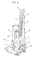
- Fig. 3 is a perspective view of the electric vacuum cleaner of Fig. 1 when seen from the rear side;
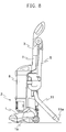
- Fig. 4 is a side view of the electric vacuum cleaner of Fig. 1 when seen from the right-hand side;
- Fig. 5 is a partially enlarged sectional view of a rear inside portion of the vacuum cleaner main body of Fig. 1;
- Fig. 6 is a view when a section along a width direction of the electric vacuum cleaner of Fig. 1 is seen from the rear side;
- Fig. 7 is an explanatory view when an attachment of the electric vacuum cleaner of Fig. 1 is being used;
- Fig. 8 is an explanatory view when a connecting hose of the electric vacuum cleaner of Fig. 1 is being used as an attachment;
- Fig. 9 is a horizontal sectional view of an interior of the rear portion of the vacuum cleaner main body of Fig. 1;
- Fig. 10 is a perspective explanatory view when an exhaust cover of Fig. 1 is in course of being attached;
- Fig. 11 is a perspective view when the exhaust cover of Fig. 1 is seen from inside;
- Fig. 12 is a sectional explanatory view of an engaging portion of a T-shaped hook of the exhaust cover of Fig. 1; and
- Fig. 13 is a sectional explanatory view of an engaging portion of a protrusion of the exhaust cover of Fig. 1.
-
- The electric vacuum cleaner of the present invention will now be explained in details with reference to the drawings.
- The upright type electric vacuum cleaner illustrated in Figs. 1 to 6 is composed of a suction tool main body 1, a vacuum cleaner
main body 2, agrip portion 3, a tipend side pipe 4 fixedly attached to thegrip portion 3, aflexible hose 5, and arotatable tube 6. A tip end portion of the tipend side pipe 4 is inserted into a tubular tip end sidepipe supporting portion 7 of the vacuum cleanermain body 2 to be supported thereby in a freely attachable and detachable manner. - The suction tool main body 1 includes a suction inlet at a lower surface thereof and a rotating brush (not shown) inside of the suction inlet. The suction tool main body 1 is communicated with a
rear portion 12 of the vacuum cleanermain body 2 through a connectinghose 11. - An
electric air blower 10 is incorporated in the vacuum cleanermain body 2, and adust box 8 is provided at an upper portion of the vacuum cleanermain body 2. The suction tool main body 1 is provided at a lower portion of the vacuum cleanermain body 2 to be freely rotating in front and rear directions through a fulcrum (not shown) which is provided at the vacuum cleanermain body 2. - The
grip portion 3 comprises of a hollow tubular body, and agrip 9 is formed at an upper end thereof. The tipend side pipe 4 and theflexible hose 5 are connected through thisgrip portion 3. Further, thegrip portion 3 is connected to the tip end sidepipe supporting portion 7 in a freely attachable and detachable manner, and it is also connected to thedust box 8 located at an upper portion on a front surface side of the vacuum cleanermain body 2 through theflexible hose 5 which is disposed on a rearward side of thegrip portion 3. - In a condition in which the
grip portion 3 is connected to the tip end sidepipe supporting portion 7, the tipend side pipe 4 is connected to the connectinghose 11 in the interior of therear portion 12 of the vacuum cleanermain body 2, so that thegrip portion 3 is in communication with the suction tool main body 1 through both of the tipend side pipe 4 and the connectinghose 11. - In the present embodiment, a
packing 13 is provided inside of therear portion 12 of the vacuum cleanermain body 2 for maintaining an air-tight condition between therear portion 12 and thegrip portion 3 as illustrated in Figs. 5 and 6. The connectinghose 11 is connected to a lower portion of thepacking 13 through screwing or similar means by utilizing concave and convex portions of the accordion-like connectinghose 11. An inner peripheral surface of the packing 13 projects inside in the radial direction so that it might abut an outer peripheral surface of the tipend side pipe 4 of thegrip portion 3, and the tipend side pipe 4 might be maintained in an air-tight condition thereby. Aguide member 14 for guiding the tipend side pipe 4 to the center of thepacking 13 is provided above thepacking 13. - In the upright type electric vacuum cleaner of the present invention having the above-described arrangement, the suction tool main body 1, the
rear portion 12 of the vacuum cleanermain body 2, thegrip portion 3 and thedust box 8 are directly connected in this order such that circulation of air is permitted, and therear portion 12 of the vacuum cleanermain body 2 and thegrip portion 3 are connected in a freely attachable and detachable manner. With this arrangement, it is possible to perform both ordinary use (floor cleaning) using the suction tool main body 1 and use of an attachment through thegrip portion 3 by utilizing one successive flow path, so that it is possible to omit a flow path switching mechanism to thereby simplify the structure. - At the time of ordinary use in which floor cleaning is performed, dust sucked through the suction tool main body 1 passes through the connecting
hose 11, the tipend side pipe 4, thegrip portion 3 and theflexible hose 5 in this order as illustrated in Figs. 4 to 6 and is accumulated in thedust box 8. - Further, as illustrated in Fig. 7, when the tip
end side pipe 4 of thegrip portion 3 is drawn out from the tip end sidepipe supporting portion 7 of the vacuum cleanermain body 2, thegrip portion 3 might be used as an attachment so that it is possible to clean ceilings or walls located at high positions. - Moreover, in the present embodiment, the portion between the suction tool main body 1 and the
rear portion 12 of the vacuum cleanermain body 2 is connected through the connectinghose 11 as illustrated in Figs. 4 and 6 to 8, and the connectinghose 11 is connected to the suction tool main body 1 in a freely attachable and detachable manner. More concretely, anadapter 11a at an end portion of the connectinghose 11 is inserted into anair inlet 1a of the suction tool main body 1 in a freely attachable and detachable manner. Accordingly, when the connectinghose 11 is drawn out from the suction tool main body 1 to change from the condition of ordinary use of Fig. 4 to the condition of Fig. 8, the connectinghose 11 might be used as an attachment, and detailed spots located at lower positions, for instance, doorsills or corners between walls and floors can be easily cleaned. That is, since it is possible to use the connectinghose 11 also as an attachment in the present embodiment, aspects of cleaning can be remarkably enlarged thereby. - In this respect, regardless of whether using the
grip portion 3 as illustrated in Fig. 7 or the connectinghose 11 as illustrated in Fig. 8, it is possible to use them by attaching an ordinarily usedextension pipe 15, a pipe for crevice 16 (see Fig. 2) or a brush for furniture 17 (see Fig. 3) to their tip ends. - Moreover, the present embodiment is so arranged that at least a part of the connecting
hose 11 is extensible and a part of the connectinghose 11 is housed in therear portion 12 of the vacuum cleanermain body 2. Accordingly, the connectinghose 11 is extended only by a length which is necessary for connection with the suction tool main body 1 for ordinary use as illustrated in Figs. 4 and 6, while the remaining portion is housed in therear portion 12 of the vacuum cleanermain body 2 in the shrunk condition so as to improve its external appearance. On the other hand, when the connectinghose 11 is to be used as an attachment, the connectinghose 11 shall be drawn out from therear portion 12 of the vacuum cleanermain body 2 so as to improve the degree of freedom of the swinging movements of the hose. It is accordingly possible to perform cleaning of a broader region using the connectinghose 11. - In this respect, while it is sufficient that at least a part of the connecting
hose 11 is extensible so that it might be housed in therear portion 12, it is also possible that the entire connectinghose 11 is extensible. - As explained so far, while the present embodiment is so arranged that the suction tool main body 1 and the
rear portion 12 of the vacuum cleanermain body 2 are connected through the connectinghose 11, the present invention is not limited to this arrangement, and it is also possible to directly connect the suction tool main body 1 and therear portion 12 of the vacuum cleanermain body 2. - Further, the electric vacuum cleaner according to the present embodiment is provided, on both sides of the
rear portion 12 of the vacuum cleanermain body 2 covering thedust box 8, with anattachment holding portion 18 and aswitch box 19 incorporating therein electric components such as switches as illustrated in Figs. 3, 6 and 9. - As illustrated in Fig. 9, the
attachment holding portion 18 is provided with throughholes extension pipe 15 and the pipe forcrevice 16 therein. In theswitch box 19, electric components such as amain switch 20, apower control switch 21, or a fuse are housed. Acord hook 23 for hooking on and accommodating a power cord thereby is integrally formed on an outer peripheral surface of theswitch box 19. - A
case 22 having a semicircular arc-like shape of the vacuum cleanermain body 2 is provided on a rear surface side of thecylindrical dust box 8. Thecase 22 is formed of a single thin plate made of synthetic resin or the like for the purpose of slimming and weight-saving of the vacuum cleanermain body 2 and a strength thereof is thus weak. However, since theattachment holding portion 18 and theswitch box 19 are fixed on both sides of the upper portion of the semicircular arc-shaped case 22 and theattachment holding portion 18 and theswitch box 19 will concurrently serve as reinforcements of thecase 22, thecase 22 itself might be manufactured to be thin so that it is possible to achieve slimming and weight-saving of the vacuum cleanermain body 2. - The electric components such as the
main switch 20, thepower control switch 21, the fuse or a fixed portion of the power cord incorporated within theswitch box 19 can be easily exchanged by simply detaching theswitch box 19. For instance, by detaching one screw for fixing theswitch box 19 to the vacuum cleanermain body 2 and two fixing screws of a switch cover on the lower surface of the switch box, it is possible to easily exchange those electric components. - Since
protrusions attachment holding portion 18 and theswitch box 19, it is possible to hold the above-describedflexible hose 5 by using theseprotrusions - As illustrated in Figs. 10 and 11, while an
exhaust cover 26 attached to a front surface of the vacuum cleanermain body 2 tends to expand outside in a width direction of theexhaust cover 26 through exhausted air when being used, since tip ends of engaging portions such as T-shapedhooks 27 on both sides of theexhaust cover 26 are fixed, the T-shapedhooks 27 are deformed inward through wind pressure and heat of the exhausted air. While no wind pressure will be present when the power switch is turned OFF, the deformation of the T-shapedhooks 27 will be still remaining so that there is the fear that the T-shapedhooks 27 might come easily off the T-shapedconcave portions 29 on the vacuum cleanermain body 2 side. - Accordingly, for preventing such falling off of the exhaust cover, the electric vacuum cleaner of the present embodiment is provided with a pair of
protrusions 28 on both sides proximate of the T-shapedhooks 27 for attaching and detaching theexhaust cover 26 thereat as illustrated in Figs. 10 to 13. On the other hand, the vacuum cleanermain body 2 is provided with a pair ofconcave portions 30 for engaging with the pair ofprotrusions 28 on both sides proximate of the T-shapedconcave portions 29 for engaging with the T-shaped hooks 27. - Accordingly, when the
exhaust cover 26 is fitted from the front of the vacuum cleanermain body 2 as illustrated in Fig. 10 such that the T-shapedhooks 27 engage with the T-shaped concave portions 29 (see Fig. 12), theprotrusions 28 on both sides of the T-shapedhooks 27 can engage with theconcave portions 30 on the vacuum cleaner main body side (see Fig. 13). Accordingly, even though pressure is applied through wind pressure of the exhausted air in a direction by which both side surfaces of theexhaust cover 26 expand outwardly at the time of using the cleaner, the engagement of theprotrusions 28 on both sides of the T-shapedhooks 27 with theconcave portions 30 will prevent outward deformation of both side surfaces of theexhaust cover 26 and thus preventing inward deformation of the T-shaped hooks 27. It is accordingly possible to prevent falling off of the above-describedexhaust cover 26. Moreover, the engagement of theprotrusions 28 and theconcave portions 30 is a simple structure, and they can be manufactured at low costs. - According to the present invention, it is possible to perform both ordinary use (floor cleaning) using a suction tool main body and use of an attachment through a grip portion by utilizing one successive flow path so that it will not be necessary to provide a flow path switching mechanism to thereby simply the arrangement.
- An electric vacuum cleaner including a vacuum cleaner main body, a suction tool main body connected to the vacuum cleaner main body and having an suction inlet which is open at a lower surface thereof, a dust box connected to the vacuum cleaner main body, and a grip portion for operating the vacuum cleaner main body. The suction tool main body, an interior of the vacuum cleaner main body, the grip portion and the dust box are directly connected in this order such that circulation of air is permitted. The interior of the vacuum cleaner main body and the grip portion are connected in a freely attachable and detachable manner. It is possible to perform both ordinary use (floor cleaning) using a suction tool main body and use of an attachment through a grip portion by utilizing one successive flow path so that it will not be necessary to provide a flow path switching mechanism to thereby simply the arrangement.
Claims (4)
- An electric vacuum cleaner comprising a vacuum cleaner main body, a suction tool main body connected to the vacuum cleaner main body and having an suction inlet which is open at a lower surface thereof, a dust box connected to the vacuum cleaner main body, and a grip portion for operating the vacuum cleaner main body, wherein the suction tool main body, an interior of the vacuum cleaner main body, the grip portion and the dust box are directly connected in this order such that circulation of air is permitted, and wherein the interior of the vacuum cleaner main body and the grip portion are connected in a freely attachable and detachable manner.
- The electric vacuum cleaner of Claim 1, wherein a packing is provided at a connecting portion of the flow path between the interior of the vacuum cleaner main body and the grip portion.
- The electric vacuum cleaner of Claim 1, wherein the suction tool main body and the interior of the vacuum cleaner main body are connected through a connecting hose, and the connecting hose is connected to the suction tool main body in a freely attachable and detachable manner.
- The electric vacuum cleaner of Claim 3, wherein at least a part of the connecting hose is extensible, and a part of the connecting hose is housed in the interior of the vacuum cleaner main body.
Applications Claiming Priority (2)
| Application Number | Priority Date | Filing Date | Title |
|---|---|---|---|
| JP2003049360A JP2004254940A (en) | 2003-02-26 | 2003-02-26 | Vacuum cleaner |
| JP2003049360 | 2003-02-26 |
Publications (1)
| Publication Number | Publication Date |
|---|---|
| EP1452119A1 true EP1452119A1 (en) | 2004-09-01 |
Family
ID=32767767
Family Applications (1)
| Application Number | Title | Priority Date | Filing Date |
|---|---|---|---|
| EP04001713A Withdrawn EP1452119A1 (en) | 2003-02-26 | 2004-01-27 | Electric vacuum cleaner |
Country Status (6)
| Country | Link |
|---|---|
| US (1) | US7350263B2 (en) |
| EP (1) | EP1452119A1 (en) |
| JP (1) | JP2004254940A (en) |
| KR (1) | KR100583680B1 (en) |
| CN (1) | CN1524484A (en) |
| CA (1) | CA2458429A1 (en) |
Cited By (2)
| Publication number | Priority date | Publication date | Assignee | Title |
|---|---|---|---|---|
| WO2005094654A1 (en) * | 2004-03-29 | 2005-10-13 | Hoover Limited | Vacuum cleaner |
| CN107260068A (en) * | 2016-04-08 | 2017-10-20 | 戴森技术有限公司 | Bar and hose for vacuum cleaner |
Families Citing this family (35)
| Publication number | Priority date | Publication date | Assignee | Title |
|---|---|---|---|---|
| USD518255S1 (en) * | 2003-08-07 | 2006-03-28 | Black & Decker Inc. | Vacuum cleaner |
| CA2514530A1 (en) * | 2004-08-04 | 2006-02-04 | Panasonic Corporation Of North America | Upright vacuum cleaner incorporating telescopic wand assembly with trigger operation |
| CA2514532C (en) * | 2004-08-04 | 2009-12-01 | Panasonic Corporation Of North America | Upright vacuum cleaner incorporating releaseable locking mechanism for wand assembly |
| US20060070205A1 (en) * | 2004-10-04 | 2006-04-06 | Panasonic Corporation Of North America | Upright vacuum cleaner incorporating telescopic wand assembly |
| GB2427999A (en) * | 2005-07-07 | 2007-01-17 | Hoover Ltd | Vacuum cleaner providing filter-absence detection |
| US7673369B2 (en) * | 2005-07-22 | 2010-03-09 | Panasonic Corporation Of North America | Floor cleaning apparatus with filter cleaning system |
| US7624475B2 (en) * | 2005-08-18 | 2009-12-01 | Ace Electronics Co., Ltd. | Upright type vacuum cleaner capable of being converted to canister type |
| US7908707B2 (en) * | 2006-03-08 | 2011-03-22 | Panasonic Corporation Of North America | Floor cleaning apparatus with filter cleaning system |
| US20070209150A1 (en) * | 2006-03-08 | 2007-09-13 | Gogel Nathan A | Floor cleaning apparatus with filter cleaning system |
| KR100934135B1 (en) * | 2007-12-26 | 2009-12-29 | 엘지전자 주식회사 | Vacuum cleaner |
| US8296901B2 (en) * | 2008-01-24 | 2012-10-30 | Euro-Pro Operating Llc | Reconfigurable airflow wand |
| US8060977B2 (en) | 2008-12-24 | 2011-11-22 | Electrolux Home Care Products, Inc. | Magnetic vacuum tool mount |
| US20100229315A1 (en) * | 2009-03-12 | 2010-09-16 | Euro-Pro Operating Llc | Handle for surface cleaning apparatus |
| US9138114B2 (en) * | 2009-03-13 | 2015-09-22 | Omachron Intellectual Property Inc. | Surface cleaning apparatus |
| SE535305C2 (en) | 2009-12-22 | 2012-06-26 | Electrolux Ab | Vacuum cleaner with retractable auxiliary suction hose |
| US8875340B2 (en) * | 2010-03-12 | 2014-11-04 | G.B.D. Corp. | Surface cleaning apparatus with enhanced operability |
| CN103876687A (en) * | 2012-12-22 | 2014-06-25 | 昆山瑞恒峰技术咨询有限公司 | Dust collector convenient to move and dispose |
| US9456721B2 (en) * | 2013-02-28 | 2016-10-04 | Omachron Intellectual Property Inc. | Surface cleaning apparatus |
| US10105022B2 (en) * | 2013-09-05 | 2018-10-23 | Samsung Electronics Co., Ltd. | Vacuum cleaner |
| GB2542198B (en) * | 2015-09-14 | 2018-01-10 | Dyson Technology Ltd | Handle assembly for a vacuum cleaner |
| GB2542197B (en) * | 2015-09-14 | 2017-12-20 | Dyson Technology Ltd | Handle assembly for a vacuum cleaner |
| US10080471B2 (en) | 2015-12-21 | 2018-09-25 | Electrolux Home Care Products, Inc. | Versatile vacuum cleaners |
| US9962050B2 (en) | 2016-08-29 | 2018-05-08 | Omachron Intellectual Property Inc. | Surface cleaning apparatus |
| US10441125B2 (en) | 2016-08-29 | 2019-10-15 | Omachron Intellectual Property Inc. | Surface cleaning apparatus |
| US10136780B2 (en) | 2016-08-29 | 2018-11-27 | Omachron Intellectual Property Inc. | Surface cleaning apparatus |
| US10441124B2 (en) | 2016-08-29 | 2019-10-15 | Omachron Intellectual Property Inc. | Surface cleaning apparatus |
| US10405711B2 (en) | 2016-08-29 | 2019-09-10 | Omachron Intellectual Property Inc. | Surface cleaning apparatus |
| US11478117B2 (en) | 2016-08-29 | 2022-10-25 | Omachron Intellectual Property Inc. | Surface cleaning apparatus |
| US10433689B2 (en) | 2016-08-29 | 2019-10-08 | Omachron Intellectual Property Inc. | Surface cleaning apparatus |
| US10292550B2 (en) * | 2016-08-29 | 2019-05-21 | Omachron Intellectual Property Inc. | Surface cleaning apparatus |
| US10413141B2 (en) | 2016-08-29 | 2019-09-17 | Omachron Intellectual Property Inc. | Surface cleaning apparatus |
| US10729295B2 (en) | 2016-08-29 | 2020-08-04 | Omachron Intellectual Property Inc. | Surface cleaning apparatus |
| US10136779B2 (en) | 2016-08-29 | 2018-11-27 | Omachron Intellectual Property Inc. | Surface cleaning apparatus |
| US10321794B2 (en) | 2016-08-29 | 2019-06-18 | Omachron Intellectual Property Inc. | Surface cleaning apparatus |
| CN218899299U (en) * | 2020-01-03 | 2023-04-25 | 创科地板护理技术有限公司 | Vacuum cleaner assembly and adapter for use with a vacuum cleaner assembly |
Citations (5)
| Publication number | Priority date | Publication date | Assignee | Title |
|---|---|---|---|---|
| US2876481A (en) * | 1955-03-09 | 1959-03-10 | Hoover Co | Suction cleaners |
| EP0437017A1 (en) * | 1990-01-12 | 1991-07-17 | Royal Appliance Manufacturing Co. | Vacuum cleaner |
| US5331715A (en) * | 1992-06-04 | 1994-07-26 | Matsushita Floor Care Company | Two motor upright vacuum cleaner |
| US5815883A (en) * | 1994-06-03 | 1998-10-06 | Stein; Klaus | Vacuum cleaner and a handle for suction lines thereof |
| US6317920B1 (en) * | 1998-11-30 | 2001-11-20 | Royal Appliance Mfg. Co. | Vacuum cleaner with above-floor cleaning tool |
Family Cites Families (8)
| Publication number | Priority date | Publication date | Assignee | Title |
|---|---|---|---|---|
| CH546567A (en) * | 1973-04-17 | 1974-03-15 | Sutter A Ag | VACUUM CLEANER. |
| US4571772A (en) * | 1982-12-27 | 1986-02-25 | Prototypes, Ltd. | Upright vacuum cleaning appliance |
| JPH05261030A (en) * | 1992-03-17 | 1993-10-12 | Sanyo Electric Co Ltd | Upright type vacuum cleaner |
| US5309600A (en) * | 1993-02-12 | 1994-05-10 | Bissell Inc. | Vacuum cleaner with a detachable vacuum module |
| JP3609582B2 (en) * | 1997-06-23 | 2005-01-12 | 三洋電機株式会社 | Electric vacuum cleaner |
| GB2359735A (en) * | 2000-03-03 | 2001-09-05 | Notetry Ltd | Hose and wand assembly for dual mode vacuum cleaner |
| JP2002233482A (en) | 2001-02-07 | 2002-08-20 | Sanyo Electric Co Ltd | Electric vacuum cleaner |
| JP2002233483A (en) * | 2001-02-07 | 2002-08-20 | Sanyo Electric Co Ltd | Electric vacuum cleaner |
-
2003
- 2003-02-26 JP JP2003049360A patent/JP2004254940A/en not_active Withdrawn
-
2004
- 2004-01-08 CN CNA2004100014373A patent/CN1524484A/en active Pending
- 2004-01-27 EP EP04001713A patent/EP1452119A1/en not_active Withdrawn
- 2004-02-18 CA CA002458429A patent/CA2458429A1/en not_active Abandoned
- 2004-02-23 KR KR1020040012000A patent/KR100583680B1/en not_active Expired - Fee Related
- 2004-02-25 US US10/788,118 patent/US7350263B2/en not_active Expired - Fee Related
Patent Citations (5)
| Publication number | Priority date | Publication date | Assignee | Title |
|---|---|---|---|---|
| US2876481A (en) * | 1955-03-09 | 1959-03-10 | Hoover Co | Suction cleaners |
| EP0437017A1 (en) * | 1990-01-12 | 1991-07-17 | Royal Appliance Manufacturing Co. | Vacuum cleaner |
| US5331715A (en) * | 1992-06-04 | 1994-07-26 | Matsushita Floor Care Company | Two motor upright vacuum cleaner |
| US5815883A (en) * | 1994-06-03 | 1998-10-06 | Stein; Klaus | Vacuum cleaner and a handle for suction lines thereof |
| US6317920B1 (en) * | 1998-11-30 | 2001-11-20 | Royal Appliance Mfg. Co. | Vacuum cleaner with above-floor cleaning tool |
Cited By (2)
| Publication number | Priority date | Publication date | Assignee | Title |
|---|---|---|---|---|
| WO2005094654A1 (en) * | 2004-03-29 | 2005-10-13 | Hoover Limited | Vacuum cleaner |
| CN107260068A (en) * | 2016-04-08 | 2017-10-20 | 戴森技术有限公司 | Bar and hose for vacuum cleaner |
Also Published As
| Publication number | Publication date |
|---|---|
| KR20040076613A (en) | 2004-09-01 |
| CN1524484A (en) | 2004-09-01 |
| KR100583680B1 (en) | 2006-05-26 |
| US20040163202A1 (en) | 2004-08-26 |
| CA2458429A1 (en) | 2004-08-26 |
| JP2004254940A (en) | 2004-09-16 |
| US7350263B2 (en) | 2008-04-01 |
Similar Documents
| Publication | Publication Date | Title |
|---|---|---|
| US7350263B2 (en) | Electric vacuum cleaner | |
| EP1510167A2 (en) | Accessory assembly for vacuum cleaners | |
| US20070039118A1 (en) | Suction hose supporting structure for upright type vacuum cleaner capable of being converted to canister type | |
| WO2001030228A1 (en) | Vacuum cleaner | |
| KR100860058B1 (en) | Hose adapter | |
| US20090217483A1 (en) | Upright type cleaner | |
| JP2004357839A (en) | Electric vacuum cleaner | |
| KR100582522B1 (en) | Accessory Support and Accessory Unit for Upright Vacuum Cleaner | |
| JP3649914B2 (en) | Vacuum cleaner | |
| JP2007185222A (en) | Vacuum cleaner | |
| JP6695031B2 (en) | Vacuum cleaner | |
| JP3181562B2 (en) | Electric vacuum cleaner | |
| KR20010049519A (en) | Electric cleaner | |
| JP5357980B2 (en) | Vertical vacuum cleaner | |
| KR100346655B1 (en) | Hoses for an Electric Cleaner and an Electric Cleaner | |
| JPH06304105A (en) | Vacuum cleaner | |
| JP2001061740A (en) | Electric vacuum cleaner | |
| JP4482999B2 (en) | Vertical vacuum cleaner | |
| JP3794321B2 (en) | Vacuum cleaner | |
| JP2008161501A (en) | Vertical vacuum cleaner | |
| KR200157812Y1 (en) | Cleaner tube | |
| JP5117965B2 (en) | Electric vacuum cleaner | |
| JP5769250B2 (en) | Vertical vacuum cleaner | |
| JP2009131304A (en) | Attachment for vacuum cleaner | |
| JPH08140903A (en) | Electric vacuum cleaner |
Legal Events
| Date | Code | Title | Description |
|---|---|---|---|
| PUAI | Public reference made under article 153(3) epc to a published international application that has entered the european phase |
Free format text: ORIGINAL CODE: 0009012 |
|
| AK | Designated contracting states |
Kind code of ref document: A1 Designated state(s): AT BE BG CH CY CZ DE DK EE ES FI FR GB GR HU IE IT LI LU MC NL PT RO SE SI SK TR |
|
| AX | Request for extension of the european patent |
Extension state: AL LT LV MK |
|
| 17P | Request for examination filed |
Effective date: 20041103 |
|
| AKX | Designation fees paid |
Designated state(s): AT BE BG CH CY CZ DE DK EE ES FI FR GB GR HU IE IT LI LU MC NL PT RO SE SI SK TR |
|
| STAA | Information on the status of an ep patent application or granted ep patent |
Free format text: STATUS: THE APPLICATION HAS BEEN WITHDRAWN |
|
| 18W | Application withdrawn |
Effective date: 20060316 |