EP1452106A1 - FASTENER STRIP WITH MAGNETIC BODY, AND METHOD AND DEVICE FOR MANUFACTURING THE FASTENER STRIP - Google Patents
FASTENER STRIP WITH MAGNETIC BODY, AND METHOD AND DEVICE FOR MANUFACTURING THE FASTENER STRIP Download PDFInfo
- Publication number
- EP1452106A1 EP1452106A1 EP02745864A EP02745864A EP1452106A1 EP 1452106 A1 EP1452106 A1 EP 1452106A1 EP 02745864 A EP02745864 A EP 02745864A EP 02745864 A EP02745864 A EP 02745864A EP 1452106 A1 EP1452106 A1 EP 1452106A1
- Authority
- EP
- European Patent Office
- Prior art keywords
- fastener strip
- extruding
- magnetic body
- magnetic
- molding cavity
- Prior art date
- Legal status (The legal status is an assumption and is not a legal conclusion. Google has not performed a legal analysis and makes no representation as to the accuracy of the status listed.)
- Granted
Links
Images













Classifications
-
- A—HUMAN NECESSITIES
- A44—HABERDASHERY; JEWELLERY
- A44B—BUTTONS, PINS, BUCKLES, SLIDE FASTENERS, OR THE LIKE
- A44B19/00—Slide fasteners
- A44B19/42—Making by processes not fully provided for in one other class, e.g. B21D53/50, B21F45/18, B22D17/16, B29D5/00
-
- B—PERFORMING OPERATIONS; TRANSPORTING
- B32—LAYERED PRODUCTS
- B32B—LAYERED PRODUCTS, i.e. PRODUCTS BUILT-UP OF STRATA OF FLAT OR NON-FLAT, e.g. CELLULAR OR HONEYCOMB, FORM
- B32B5/00—Layered products characterised by the non- homogeneity or physical structure, i.e. comprising a fibrous, filamentary, particulate or foam layer; Layered products characterised by having a layer differing constitutionally or physically in different parts
- B32B5/18—Layered products characterised by the non- homogeneity or physical structure, i.e. comprising a fibrous, filamentary, particulate or foam layer; Layered products characterised by having a layer differing constitutionally or physically in different parts characterised by features of a layer of foamed material
-
- A—HUMAN NECESSITIES
- A44—HABERDASHERY; JEWELLERY
- A44B—BUTTONS, PINS, BUCKLES, SLIDE FASTENERS, OR THE LIKE
- A44B18/00—Fasteners of the touch-and-close type; Making such fasteners
- A44B18/0046—Fasteners made integrally of plastics
- A44B18/0049—Fasteners made integrally of plastics obtained by moulding processes
-
- A—HUMAN NECESSITIES
- A44—HABERDASHERY; JEWELLERY
- A44B—BUTTONS, PINS, BUCKLES, SLIDE FASTENERS, OR THE LIKE
- A44B18/00—Fasteners of the touch-and-close type; Making such fasteners
- A44B18/0069—Details
- A44B18/0076—Adaptations for being fixed to a moulded article during moulding
-
- B—PERFORMING OPERATIONS; TRANSPORTING
- B29—WORKING OF PLASTICS; WORKING OF SUBSTANCES IN A PLASTIC STATE IN GENERAL
- B29C—SHAPING OR JOINING OF PLASTICS; SHAPING OF MATERIAL IN A PLASTIC STATE, NOT OTHERWISE PROVIDED FOR; AFTER-TREATMENT OF THE SHAPED PRODUCTS, e.g. REPAIRING
- B29C33/00—Moulds or cores; Details thereof or accessories therefor
- B29C33/12—Moulds or cores; Details thereof or accessories therefor with incorporated means for positioning inserts, e.g. labels
- B29C33/14—Moulds or cores; Details thereof or accessories therefor with incorporated means for positioning inserts, e.g. labels against the mould wall
- B29C33/16—Moulds or cores; Details thereof or accessories therefor with incorporated means for positioning inserts, e.g. labels against the mould wall using magnetic means
-
- B—PERFORMING OPERATIONS; TRANSPORTING
- B29—WORKING OF PLASTICS; WORKING OF SUBSTANCES IN A PLASTIC STATE IN GENERAL
- B29C—SHAPING OR JOINING OF PLASTICS; SHAPING OF MATERIAL IN A PLASTIC STATE, NOT OTHERWISE PROVIDED FOR; AFTER-TREATMENT OF THE SHAPED PRODUCTS, e.g. REPAIRING
- B29C48/00—Extrusion moulding, i.e. expressing the moulding material through a die or nozzle which imparts the desired form; Apparatus therefor
- B29C48/03—Extrusion moulding, i.e. expressing the moulding material through a die or nozzle which imparts the desired form; Apparatus therefor characterised by the shape of the extruded material at extrusion
- B29C48/07—Flat, e.g. panels
- B29C48/08—Flat, e.g. panels flexible, e.g. films
-
- B—PERFORMING OPERATIONS; TRANSPORTING
- B29—WORKING OF PLASTICS; WORKING OF SUBSTANCES IN A PLASTIC STATE IN GENERAL
- B29C—SHAPING OR JOINING OF PLASTICS; SHAPING OF MATERIAL IN A PLASTIC STATE, NOT OTHERWISE PROVIDED FOR; AFTER-TREATMENT OF THE SHAPED PRODUCTS, e.g. REPAIRING
- B29C48/00—Extrusion moulding, i.e. expressing the moulding material through a die or nozzle which imparts the desired form; Apparatus therefor
- B29C48/03—Extrusion moulding, i.e. expressing the moulding material through a die or nozzle which imparts the desired form; Apparatus therefor characterised by the shape of the extruded material at extrusion
- B29C48/12—Articles with an irregular circumference when viewed in cross-section, e.g. window profiles
-
- B—PERFORMING OPERATIONS; TRANSPORTING
- B29—WORKING OF PLASTICS; WORKING OF SUBSTANCES IN A PLASTIC STATE IN GENERAL
- B29C—SHAPING OR JOINING OF PLASTICS; SHAPING OF MATERIAL IN A PLASTIC STATE, NOT OTHERWISE PROVIDED FOR; AFTER-TREATMENT OF THE SHAPED PRODUCTS, e.g. REPAIRING
- B29C48/00—Extrusion moulding, i.e. expressing the moulding material through a die or nozzle which imparts the desired form; Apparatus therefor
- B29C48/03—Extrusion moulding, i.e. expressing the moulding material through a die or nozzle which imparts the desired form; Apparatus therefor characterised by the shape of the extruded material at extrusion
- B29C48/13—Articles with a cross-section varying in the longitudinal direction, e.g. corrugated pipes
-
- B—PERFORMING OPERATIONS; TRANSPORTING
- B29—WORKING OF PLASTICS; WORKING OF SUBSTANCES IN A PLASTIC STATE IN GENERAL
- B29C—SHAPING OR JOINING OF PLASTICS; SHAPING OF MATERIAL IN A PLASTIC STATE, NOT OTHERWISE PROVIDED FOR; AFTER-TREATMENT OF THE SHAPED PRODUCTS, e.g. REPAIRING
- B29C48/00—Extrusion moulding, i.e. expressing the moulding material through a die or nozzle which imparts the desired form; Apparatus therefor
- B29C48/25—Component parts, details or accessories; Auxiliary operations
- B29C48/285—Feeding the extrusion material to the extruder
- B29C48/29—Feeding the extrusion material to the extruder in liquid form
-
- B—PERFORMING OPERATIONS; TRANSPORTING
- B29—WORKING OF PLASTICS; WORKING OF SUBSTANCES IN A PLASTIC STATE IN GENERAL
- B29C—SHAPING OR JOINING OF PLASTICS; SHAPING OF MATERIAL IN A PLASTIC STATE, NOT OTHERWISE PROVIDED FOR; AFTER-TREATMENT OF THE SHAPED PRODUCTS, e.g. REPAIRING
- B29C48/00—Extrusion moulding, i.e. expressing the moulding material through a die or nozzle which imparts the desired form; Apparatus therefor
- B29C48/25—Component parts, details or accessories; Auxiliary operations
- B29C48/30—Extrusion nozzles or dies
- B29C48/35—Extrusion nozzles or dies with rollers
-
- B—PERFORMING OPERATIONS; TRANSPORTING
- B32—LAYERED PRODUCTS
- B32B—LAYERED PRODUCTS, i.e. PRODUCTS BUILT-UP OF STRATA OF FLAT OR NON-FLAT, e.g. CELLULAR OR HONEYCOMB, FORM
- B32B27/00—Layered products comprising a layer of synthetic resin
- B32B27/06—Layered products comprising a layer of synthetic resin as the main or only constituent of a layer, which is next to another layer of the same or of a different material
- B32B27/065—Layered products comprising a layer of synthetic resin as the main or only constituent of a layer, which is next to another layer of the same or of a different material of foam
-
- B—PERFORMING OPERATIONS; TRANSPORTING
- B32—LAYERED PRODUCTS
- B32B—LAYERED PRODUCTS, i.e. PRODUCTS BUILT-UP OF STRATA OF FLAT OR NON-FLAT, e.g. CELLULAR OR HONEYCOMB, FORM
- B32B27/00—Layered products comprising a layer of synthetic resin
- B32B27/30—Layered products comprising a layer of synthetic resin comprising vinyl (co)polymers; comprising acrylic (co)polymers
- B32B27/304—Layered products comprising a layer of synthetic resin comprising vinyl (co)polymers; comprising acrylic (co)polymers comprising vinyl halide (co)polymers, e.g. PVC, PVDC, PVF, PVDF
-
- B—PERFORMING OPERATIONS; TRANSPORTING
- B32—LAYERED PRODUCTS
- B32B—LAYERED PRODUCTS, i.e. PRODUCTS BUILT-UP OF STRATA OF FLAT OR NON-FLAT, e.g. CELLULAR OR HONEYCOMB, FORM
- B32B27/00—Layered products comprising a layer of synthetic resin
- B32B27/32—Layered products comprising a layer of synthetic resin comprising polyolefins
-
- B—PERFORMING OPERATIONS; TRANSPORTING
- B32—LAYERED PRODUCTS
- B32B—LAYERED PRODUCTS, i.e. PRODUCTS BUILT-UP OF STRATA OF FLAT OR NON-FLAT, e.g. CELLULAR OR HONEYCOMB, FORM
- B32B27/00—Layered products comprising a layer of synthetic resin
- B32B27/34—Layered products comprising a layer of synthetic resin comprising polyamides
-
- B—PERFORMING OPERATIONS; TRANSPORTING
- B32—LAYERED PRODUCTS
- B32B—LAYERED PRODUCTS, i.e. PRODUCTS BUILT-UP OF STRATA OF FLAT OR NON-FLAT, e.g. CELLULAR OR HONEYCOMB, FORM
- B32B27/00—Layered products comprising a layer of synthetic resin
- B32B27/36—Layered products comprising a layer of synthetic resin comprising polyesters
-
- B—PERFORMING OPERATIONS; TRANSPORTING
- B32—LAYERED PRODUCTS
- B32B—LAYERED PRODUCTS, i.e. PRODUCTS BUILT-UP OF STRATA OF FLAT OR NON-FLAT, e.g. CELLULAR OR HONEYCOMB, FORM
- B32B27/00—Layered products comprising a layer of synthetic resin
- B32B27/40—Layered products comprising a layer of synthetic resin comprising polyurethanes
-
- B—PERFORMING OPERATIONS; TRANSPORTING
- B32—LAYERED PRODUCTS
- B32B—LAYERED PRODUCTS, i.e. PRODUCTS BUILT-UP OF STRATA OF FLAT OR NON-FLAT, e.g. CELLULAR OR HONEYCOMB, FORM
- B32B3/00—Layered products comprising a layer with external or internal discontinuities or unevennesses, or a layer of non-planar shape; Layered products comprising a layer having particular features of form
- B32B3/02—Layered products comprising a layer with external or internal discontinuities or unevennesses, or a layer of non-planar shape; Layered products comprising a layer having particular features of form characterised by features of form at particular places, e.g. in edge regions
- B32B3/06—Layered products comprising a layer with external or internal discontinuities or unevennesses, or a layer of non-planar shape; Layered products comprising a layer having particular features of form characterised by features of form at particular places, e.g. in edge regions for securing layers together; for attaching the product to another member, e.g. to a support, or to another product, e.g. groove/tongue, interlocking
-
- B—PERFORMING OPERATIONS; TRANSPORTING
- B32—LAYERED PRODUCTS
- B32B—LAYERED PRODUCTS, i.e. PRODUCTS BUILT-UP OF STRATA OF FLAT OR NON-FLAT, e.g. CELLULAR OR HONEYCOMB, FORM
- B32B33/00—Layered products characterised by particular properties or particular surface features, e.g. particular surface coatings; Layered products designed for particular purposes not covered by another single class
-
- B—PERFORMING OPERATIONS; TRANSPORTING
- B60—VEHICLES IN GENERAL
- B60N—SEATS SPECIALLY ADAPTED FOR VEHICLES; VEHICLE PASSENGER ACCOMMODATION NOT OTHERWISE PROVIDED FOR
- B60N2/00—Seats specially adapted for vehicles; Arrangement or mounting of seats in vehicles
- B60N2/58—Seat coverings
- B60N2/5816—Seat coverings attachments thereof
- B60N2/5833—Seat coverings attachments thereof by hook-and-loop type fasteners
-
- A—HUMAN NECESSITIES
- A44—HABERDASHERY; JEWELLERY
- A44D—INDEXING SCHEME RELATING TO BUTTONS, PINS, BUCKLES OR SLIDE FASTENERS, AND TO JEWELLERY, BRACELETS OR OTHER PERSONAL ADORNMENTS
- A44D2203/00—Fastening by use of magnets
-
- B—PERFORMING OPERATIONS; TRANSPORTING
- B29—WORKING OF PLASTICS; WORKING OF SUBSTANCES IN A PLASTIC STATE IN GENERAL
- B29C—SHAPING OR JOINING OF PLASTICS; SHAPING OF MATERIAL IN A PLASTIC STATE, NOT OTHERWISE PROVIDED FOR; AFTER-TREATMENT OF THE SHAPED PRODUCTS, e.g. REPAIRING
- B29C48/00—Extrusion moulding, i.e. expressing the moulding material through a die or nozzle which imparts the desired form; Apparatus therefor
- B29C48/25—Component parts, details or accessories; Auxiliary operations
- B29C48/285—Feeding the extrusion material to the extruder
- B29C48/288—Feeding the extrusion material to the extruder in solid form, e.g. powder or granules
-
- B—PERFORMING OPERATIONS; TRANSPORTING
- B29—WORKING OF PLASTICS; WORKING OF SUBSTANCES IN A PLASTIC STATE IN GENERAL
- B29K—INDEXING SCHEME ASSOCIATED WITH SUBCLASSES B29B, B29C OR B29D, RELATING TO MOULDING MATERIALS OR TO MATERIALS FOR MOULDS, REINFORCEMENTS, FILLERS OR PREFORMED PARTS, e.g. INSERTS
- B29K2105/00—Condition, form or state of moulded material or of the material to be shaped
- B29K2105/0005—Condition, form or state of moulded material or of the material to be shaped containing compounding ingredients
-
- B—PERFORMING OPERATIONS; TRANSPORTING
- B29—WORKING OF PLASTICS; WORKING OF SUBSTANCES IN A PLASTIC STATE IN GENERAL
- B29K—INDEXING SCHEME ASSOCIATED WITH SUBCLASSES B29B, B29C OR B29D, RELATING TO MOULDING MATERIALS OR TO MATERIALS FOR MOULDS, REINFORCEMENTS, FILLERS OR PREFORMED PARTS, e.g. INSERTS
- B29K2105/00—Condition, form or state of moulded material or of the material to be shaped
- B29K2105/06—Condition, form or state of moulded material or of the material to be shaped containing reinforcements, fillers or inserts
- B29K2105/16—Fillers
-
- B—PERFORMING OPERATIONS; TRANSPORTING
- B29—WORKING OF PLASTICS; WORKING OF SUBSTANCES IN A PLASTIC STATE IN GENERAL
- B29K—INDEXING SCHEME ASSOCIATED WITH SUBCLASSES B29B, B29C OR B29D, RELATING TO MOULDING MATERIALS OR TO MATERIALS FOR MOULDS, REINFORCEMENTS, FILLERS OR PREFORMED PARTS, e.g. INSERTS
- B29K2995/00—Properties of moulding materials, reinforcements, fillers, preformed parts or moulds
- B29K2995/0003—Properties of moulding materials, reinforcements, fillers, preformed parts or moulds having particular electrical or magnetic properties, e.g. piezoelectric
- B29K2995/0008—Magnetic or paramagnetic
-
- B—PERFORMING OPERATIONS; TRANSPORTING
- B29—WORKING OF PLASTICS; WORKING OF SUBSTANCES IN A PLASTIC STATE IN GENERAL
- B29L—INDEXING SCHEME ASSOCIATED WITH SUBCLASS B29C, RELATING TO PARTICULAR ARTICLES
- B29L2031/00—Other particular articles
- B29L2031/727—Fastening elements
- B29L2031/729—Hook and loop-type fasteners
-
- B—PERFORMING OPERATIONS; TRANSPORTING
- B32—LAYERED PRODUCTS
- B32B—LAYERED PRODUCTS, i.e. PRODUCTS BUILT-UP OF STRATA OF FLAT OR NON-FLAT, e.g. CELLULAR OR HONEYCOMB, FORM
- B32B2307/00—Properties of the layers or laminate
- B32B2307/20—Properties of the layers or laminate having particular electrical or magnetic properties, e.g. piezoelectric
- B32B2307/208—Magnetic, paramagnetic
Definitions
- the present invention relates to a field of an engaging/disengaging tool, and particularly, the present invention relates to a fastener strip having magnetic bodies not distributed through an entire volume thereof but distributed in individual discontinuous identification areas thereof and a method and a device for manufacturing the fastener strip.
- a sheet for a motor vehicle or the like is made by a structure that a cushion body is covered with a skin material on the cushion body, and a structure having a concave shape which satisfies conditions of keeping a seating posture and no fatigue from seating for long time ergonomically is adopted.
- a concave shaped sheet in order to prevent the skin material from floating from the cushion body at a concave shaped portion, by using a foam molded article with a fastener strip 10 fixed on the concave shaped portion as shown in FIG. 34 as a cushion body 9, the fastener strip 10 that is integrally formed to the cushion body 9 and a fastener strip (not shown) attached on a liner of the skin material are adhered and engaged so as to evade floating of the skin material.
- FIG. 15 shows an example of manufacturing a cushion body with the fastener strip integrally formed on the surface of the foam molded article.
- a cushion body as a foam molded article is manufactured, in which the fastener strip 10 is integrally formed thereon.
- a component capable of being magnetically sucked namely, a magnetic material has various figurations including a metallic major component, a steel strip or a shim, a wire, a porous metal web or a woven screen or a magnetic particle.
- a configuration that the magnetic body is disposed substantially on an entire surface of the fastener strip in order to raise a suction force for a magnet in a forming die JP-A-4-109904, USP Nos. 4673542, 5725928, and 5945193
- a configuration disposing many magnetic suction members in adjacent to the both edges of the substrate of the fastener strip USP No. 5654070
- USP No. 5500268 discloses a magnetic particle to be contained in a foam seal used for, for example, preventing an engaging element from being contaminated upon molding.
- Each publication of USP Nos. 4563380, 4710414 and 4784890 discloses that the magnetic particles are blended in an adhesive agent to be used for attaching various elements of the fastener strip such as a fixed layer or a backing layer.
- USP No. 5540970 discloses a fastener strip having magnetic particles that are embedded in a container to encircle a hook so as to prevent contamination. This container is detached later, after finishing a molding process. Further, in USP No. 5945193, a backing disposed on a rear surface or a base portion of a fastener base portion, a porous metal web embedded in a substrate layer, or a woven screen is described.
- each publication of USP Nos. 5725928 and 5932311 describes a touch fastener and a method for manufacturing the same, respectively.
- the magnetic particles are contained in an entire hook or a base portion layer, or in an entire substrate layer to be pushed out together with the hook and the base portion layer. This is attained by blending a ferromagnet in a flow of resin to be supplied to an entire extruding machine in advance.
- a publication of USP No. 5766723 describes a fastener assembly and here, the magnetic particles are contained in an entire hook and a base portion layer, or in an entire backing layer to be disposed to the hook and the base portion layer thereafter.
- the conventional fastener strip is configured focusing on enhancement of the magnetic force, when a fastener strip is merely mounted on a forming die, the fastener strip is sucked and fixed on that position and it is difficult to position the fastener strip. Therefore, it is necessary to place the fastener strips one by one as positioning them by hand. This results in a problem such that workability for mounting the fastener strip is low and it takes long time for a mounting operation, so that improvement for this has been required.
- the foam resin enters between the engaging elements of the fastener strip to contaminate the engaging elements and the engagement function thereof is lowered.
- a strip body and a stopper member are formed at the both edges of the fastener strip so as to prevent the foam resin from entering the surface of the engaging element by these strip body and stopper member (Japanese Utility Model Application Publication (JP-Y) Nos. 4-53685, and 6-37712), and further, it is suggested that the entire engaging element is covered with a film so as to prevent the foam resin from entering the surface of the engaging element upon molding (JP-A-60-179003).
- the sealing means is not made of the same materials as the fastener layer and rather, this involves a serious defect that the sealing means is made of a different material which is attached to the foreside of the fastener layer afterwards. This makes a manufacturing cost higher and more complex as compared to the fastener strip having the sealing means that is integrally formed from the same material as the fastener layer.
- the prior art adopting the protection cover in order to evade contamination has the following defects.
- the cover should be removed after completing the molding, and another process should be often added to the molding process, which is complex and takes time.
- the magnetic body in the base portion, in the member to be integrally molded with the base portion, or in the substrate layer so that there is no necessity to dispose this magnetic body across the width of the fastener strip entirely.
- the magnetic particles can be entered only in the foam or in the base portion below the side portion seal of the other type, so that the magnetic force only acts on the side portion of the strip.
- the magnetic particles or a long magnetic body can be entered only along a center in a longitudinal direction of the strip and thereby, the strip can be easily disposed in a metal mold.
- the resin containing the magnetic particles can be removed quickly and easily from an extruding machine or another device. Therefore, since it is not necessary to remove the magnetic particles from the entire extruding machine, cycle while extruding the strip with or without the magnetic particles by using the same device becomes simple. Alternately, only a portion where the magnetic particles moves may be cleaned up. In accordance to needs, a line or a passage in which the magnetic particles are introduced can be opened or closed. Thereby, it is possible to increase flexibility in the manufacturing process and to make the cycle time shorter.
- the present invention makes it possible to limit these affects on a particularly defined scope.
- a staggered member forming a seal to prevent contamination by entering of a foam resin upon molding a foam product can be simply made of the same element as the remaining portion of the fastener layer.
- An entering amount of the foam to be hardened can be controlled so as to fix the fastener strip to an object to be molded at a constant rate by the staggered member.
- an interval of the staggered members can be changed so that the foam penetrates more in the outside edge of the strip to have the optimum fixing of the fastener strip, or in order to have the optimum fixing of the fastener strip, it can be changed from that minimum amounts of penetration till no penetration at the predetermined length inside from the edge.
- an edge of the fastener strip is flexible along a length of the fastener strip in accordance to need and it can correspond to a curved or concavo-convex surface of a metal mold. Nevertheless, the fastener strip can realize excellent sealing.
- the present invention provides a fastener strip having a magnetic material capable of being magnetically sucked and not distributed through the entire volume of the strip and contained in individual discontinuous identification areas thereof. Further, a method for manufacturing such a strip is also described below.
- a basic configuration of the present invention comprises an engaging/disengaging tool capable of being magnetically fixed on an object, including: (a) a substrate; (b) at least one engaging element to be supported on the substrate; and (c) a magnetic body disposed in a discontinuous area of the substrate or in a discontinuous area of at least one engaging element that is supported on the substrate and integrally formed.
- the magnetic body is not disposed on the entire surface of the substrate but disposed in the discontinuous area which is a part of the substrate, unnecessary usage of the magnetic material is evaded and further, it is possible to take full advantage of a suction force of magnetism.
- the magnetic body is disposed in the discontinuous area of the substrate along a longitudinal direction of the substrate, and it is more preferable that the magnetic body is disposed in substantially a lateral center of the discontinuous area of the substrate along the longitudinal direction, or the magnetic body is disposed in a discontinuous area of the substrate along a lateral side portion of the substrate in the longitudinal direction, because it is easy to give a directionality to the fastener strip upon positioning on a forming die.
- this magnetic body also functions as a wall such as a molding resin or the like, which prevents a foam resin from entering an area on which an engaging element is formed upon molding a cushion or the like.
- the magnetic body has a narrow figuration that is extended in a longitudinal direction of the substrate and further, depending on a magnet disposed at a predetermined position of a forming die, the magnetic body has a sufficient magnetism for allowing the longitudinal both ends of the fastener strip to correspond with a bipolar direction of this magnet.
- a narrow and long magnetic body when a narrow and long magnetic body is placed in a magnetic field caused by the magnet, the magnetic body is magnetized by the magnetic field. At the both ends in a longitudinal direction of the magnetized magnetic body, magnetic poles of + and - are caused, respectively.
- a moving force may act on this magnetic body to allow the magnetic body to face in the bipolar direction of the magnet and the magnetic body is made in a condition facing to the bipolar direction of the magnet. Further, the magnetic body is magnetically sucked to a vicinity of a center of the both magnetic poles.
- the both ends in a longitudinal direction of the fastener strip face to the direction of the both poles of the magnet by the magnetism, so that the both ends in a longitudinal direction correspond with the direction of the both poles of the magnet, as described above.
- the fastener strip having this wide magnetic body is mounted on the magnet with the longitudinal direction of this magnetic body inclined to the direction of the both poles of the magnet, the longitudinal direction of this magnetic body is magnetically sucked as it is inclined to the both magnetic poles of the magnet. As a result, the longitudinal direction of the fastener strip does not face to the bipolar direction of the magnet.
- the same force as the above-described one also acts on the long and wide magnetic body, as compared to movement due to the magnetism of the narrow magnetic body, the movement of the wide magnetic body is small because the above-described force does not act on the wide magnetic body as a magnetism sufficient for facing this wide magnetic body to the bipolar direction of the magnet.
- the above-described phenomenon caused by the long and narrow magnetic body and the magnet is applied to the fastener strip. Only by providing the continuous narrow magnetic body along a longitudinal direction of a fastener strip substrate and mounting this fastener strip in the vicinity of a predetermined mounting place on the forming die, the above-described phenomenon can be used and the fastener strip can be positioned and fixed on a desired position even if a positional relation between the longitudinal direction of the fastener strip substrate and a position of the both magnetic poles of the magnet located on the mounting position is not taken seriously.
- a narrow width of the magnetic body of the present invention can be changed depending on the size of the fastener strip on which the same narrow magnetic body is displaced and the strength of the magnetic field of the magnet that is located in the forming die. If the strength of the magnetic poles at the both ends of the magnetic body caused by this magnet and a force acting on this magnetic body by the magnetic flux density of this magnet can be set at a sufficient level to correspond the both ends of a longitudinal direction of the fastener strip with the direction of the both poles of this magnet, an arbitrary width can be set.
- the magnetic body having a narrow figuration extending in the longitudinal direction of the fastener strip substrate may be continued in the longitudinal direction. Further, it may be discontinuous in the longitudinal direction. Both of a continuous figuration and a discontinuous figuration as a figuration of the magnetic body have a function as a magnetic body causing the above-described phenomena.
- the magnetic body when the magnetic body is disposed at a center of the substrate in a width direction or at a lateral edge thereof so as to be extended along a longitudinal direction, it is possible to act a suction force by the magnetic body and the magnet at a center of the fastener strip and in addition to this effect, it possible to strongly move the both ends in the longitudinal direction at a center in a width direction of the above-described fastener strip toward the direction of the both poles of the magnet.
- the above-described magnetic body is made of at least one element of a synthetic resin-made projecting portion in which the magnetic particles are mixed, and a surface of the projecting portion is preferably covered with a synthetic resin material made of the same material as the substrate. Due to this configuration, when the resin used for the magnetic body and the resin used for the fastener strip lack in affinity, separation between the projecting portion and the main body of the fastener strip can be evaded.
- the above-described magnetic body may be disposed on the above-described substrate itself, however, it can be made into at least one synthetic resin projecting portion including the magnetic material formed on the surface of the substrate.
- a magnetic material to be contained in the synthetic resin projecting portion may be a magnetic particle to be mixed or added to the synthetic resin material, or it may be a long magnetic material such as a magnetic metal wire rod or a magnetic tape, or a woven and knitted fabric that is woven and knitted from a synthetic resin fiber having a metal fiber or a magnetic particle mixed therein or a nonwoven cloth.
- the synthetic resin projecting portions may be continuously formed in a longitudinal direction of the substrate, however, valley portions may be formed at equal intervals along the longitudinal direction of the substrate.
- valley portions may be formed at equal intervals along the longitudinal direction of the substrate.
- the magnetic material is made of the magnetic particle
- the magnetic particle such as iron, cobalt, and nickel is preferable.
- the projecting portion is molded; or after molding the projecting portion, by applying coating having the magnetic particles on the upper surface of the projecting portion or laminating the resin film containing the magnetic particles on the projecting portion, the projecting portion can be made.
- the long magnetic body can be extended along the above-mentioned projecting portion, and particularly, the long magnetic material is extended with inserted through the inside of the projecting portion so that the long magnetic material is partially exposed at the valley portion of the projecting portion.
- Such a configuration makes it easy to integrate the projecting portion made of the synthetic resin material and the long magnetic material, of which physical properties are different each other, and the configuration can make the fastener strip flexible by the valley portion which is formed at the projecting portion.
- the above-described magnetic body can be also made of a plurality of engaging elements, which contain the magnetic member and of which base parts are connected to each other.
- the magnetic body having such a configuration has no need to form a cavity for the projecting portion separately.
- the plural engaging elements containing the magnetic material that are arranged in a row in a longitudinal direction function as the long magnetic body when mounting the fastener strip on the forming die, and after the fastener strip is integrally formed on the surface of the foam molded article, they can carry out an original function of the engaging element.
- the above-described projecting portion including the engaging element row that functions as the above-mentioned magnetic body is made of a thermoplastic resin to be integrally molded on the substrate.
- the thermoplastic resin may include polyester, polyamide, polyolefin, polyvinyl chloride, polyurethane, polyolefin erastomer, polyester erastomer, polyamide erastomer, polyisoprene, and other synthetic resin such as a resin composition containing a thermoplastic polymer.
- the above-described magnetic body combining a function as a wall for preventing entering of the molding resin that is disposed along the side edge of the substrate is made of a plurality of wall portions that are arranged in a row at predetermined intervals.
- the above-mentioned wall portion is not necessary to be the magnetic body.
- two or more rows of the wall portions are disposed at predetermined intervals and they are arranged in a staggered shape in a row direction.
- the wall portion When the strip is embedded and molded in the object such as a foam or the like, the wall portion may form a seal effective for preventing contamination of a hook and a loop.
- the configuration of the fastener strip can be made simple and without providing a fixing member separately, it is possible to enhance a function to fix the fastener strip on the molded body.
- a passage having a required length in the passage direction of the foam resin is formed, and the fastener strip allows the foam resin to enter the engaging element through this passage.
- Resistance caused by this passage carries out a regulation function to make the entering amount of the engaging element into the foam resin small, and carries out a function to fix the wall portion more solidly as a fixing member because a contact area between the entered foam resin and the wall portion is increased.
- the passage has a dead end portion.
- a narrow passage is the dead end portion, namely, a dead alley, and this dead end portion can prevent the foam resin from entering the engaging element.
- the wall portion carries out its function as a more solid fixing member.
- further entering is regulated by a portion of the engaging element that is formed at the inside of the wall portion.
- a portion of the engaging element is provided with a function as an anchor member for preventing entering of the foam resin.
- the substrate and the wall portion, or the substrate, the wall portion and the engaging element are integrally molded by the thermoplastic resin.
- Each of the both side edges of the substrate has at least two rows of the wall portions along the longitudinal direction, at least one row of the wall portions to be disposed at the most outside of the both side edges has many wall portions to be disposed along the longitudinal direction, and the inside wall portion in adjacent to these wall portions may be configured by the continuous wall portion. It is possible to prevent the foam resin that is regulated by the outside wall and is passed through the gaps between the wall portions from entering the engaging element by the inside continuous wall portion.
- a plurality of engaging element groups are defined and are formed along the longitudinal direction of the surface of the substrate, and each engaging element group is surrounded by at least one wall portion and at least one lateral wall portion.
- a plurality of engaging element groups are defined and are formed along the longitudinal direction of the surface of the substrate, each engaging element group is surrounded by at least one wall portion, and the lateral wall portion surrounding the engaging element groups prevents the foam resin from entering the engaging element.
- the above-described lateral wall portion in adjacent to the engaging element group may be composed of the continuous wall portion or the plural intermittent wall portions that are disposed at intervals.
- the height of the wall portion and the height of the lateral wall portion are preferably the height of the engaging element or more.
- the wall portion, the lateral wall portion, and the surface of the forming die closely contact with one another, and the gaps are not formed among the wall portion, the lateral wall portion, and the surface of the forming die.
- the heights of the wall portion and the lateral wall portion may be lower than the height of the engaging element.
- the engaging element group is fit in the concave portion on the surface of the forming die, this makes the wall portion and the lateral wall portion to closely contact each other around the concave portion, and this results in that no gap is formed among the wall portion, the lateral wall portion, and the surface of the forming die. Therefore, it is possible to effectively prevent the foam resin between the wall portion, the lateral wall portion, and the surface of the forming die from entering the engaging element.
- the fastener strip provided with the above configurations is efficiently manufactured by a manufacturing method and a manufacturing device according to the present invention, which are described below.
- a method for manufacturing a fastener strip comprising steps of: (a) disposing a magnetic powder substance; and (b) injecting the magnetic powder substance into a discontinuous area of a substrate layer of an engaging/disengaging tool or into a discontinuous area that is provided with at least one integrated member to be carried on the substrate layer of the engaging/disengaging tool, wherein the engaging/disengaging tool can be magnetically fixed on an object.
- the step of injecting the magnetic powder substance comprises a step of extruding a plastic resin through an extruding machine and introducing the magnetic powder substance through another passage in the extruding machine.
- Said another passage has an outlet port that is disposed on substantially a center of a front surface of the extruding machine.
- a mixture of the plastic resin and the magnetic powder substance is extruded to the substrate of the fastener strip and the projecting portion through the another passage in the extruding machine.
- the step of injecting the magnetic powder substance includes a step of extruding the plastic resin through the extruding machine toward and extruding the magnetic body through another line, toward a die wheel in adjacent to the extruding machine.
- a cavity for molding this magnetic body is preferably disposed at substantially a center and/or a side edge of the periphery surface of the die wheel.
- a device for manufacturing a fastener strip comprising: a magnetic body molding portion having a first extruding die, which has an extruding port for extruding a synthetic resin material in a molten state in which magnetic powders are mixed, and a first die wheel which rotates around a horizontal axis as facing to the extruding port and which has a magnetic body molding cavity that is formed along a periphery surface of the rotational direction; and a fastener strip molding portion having a second extruding die having an extruding port for extruding a synthetic resin in a molted state, a second die wheel which rotates around a horizontal axis as facing to the extruding port and which has a fastener strip molding cavity that is formed along a periphery surface in the rotational direction, and a magnetic body guide portion which is located at an upstream side in a rotational direction of the second die wheel with respect to
- the device for manufacturing the fastener strip is characterized in that a pair of manufacturing devices (a magnetic body molding portion and a fastener strip molding portion) comprising an extruding die having an extruding port for extruding a synthetic resin material in a molten state, and a die wheel which rotates around a horizontal axis as facing to the extruding port and has molding cavities that are formed along a periphery surface of the rotational direction is provided, and one manufacturing device (the magnetic body molding portion) manufactures a magnetic molded article and the other manufacturing device (the fastener strip molding portion) manufactures a fastener strip molded article in which this magnetic molded article is integrally molded.
- a pair of manufacturing devices (a magnetic body molding portion and a fastener strip molding portion) comprising an extruding die having an extruding port for extruding a synthetic resin material in a molten state, and a die wheel which rotates around a horizontal axis as facing to the extruding port
- the magnetic body molding cavity including concave portions for projecting portions having narrow configurations, which are continued in a peripheral direction or are intermittently disposed
- the fastener strip molding cavity including concave portions for engaging elements that are disposed at a predetermined pitch in a peripheral direction, and concave portions for accommodating the magnetic molded article molded by the magnetic body molding portion.
- a synthetic resin material having magnetic powders mixed therein and in a molten state is extruded from a first extruding die extruding port, and the synthetic resin material is continuously filled in the magnetic body molding cavity while rotating the first die wheel; and then, a magnetic body molded article is peeled off from a peripheral surface of the first die wheel.
- a synthetic resin material in a molten state is extruded from a second extruding die extruding port, and the synthetic resin material is continuously filled in the fastener strip molding cavity while rotating the second die wheel; and then, the magnetic body molded article is continuously supplied to the concave portion for accommodation in the fastener strip molding cavity through the magnetic body guide portion.
- a fastener strip molded article including the engaging element and a magnetic body having a narrow configuration is peeled off from the second die wheel.
- a fastener strip is manufactured.
- the fastener strip having the magnetic body by supplying the magnetic molded article molded by the first die wheel not through the take-up real or the like to the second die wheel as it is through the magnetic body guide portion.
- a dancer roller is disposed between the take-up real or the like and the second die wheel, and when supplying the magnetic molded article not through the take-up real or the like, a dancer roller is disposed between the second die wheel and a raw material guide port, so that it is possible to prevent a slack of the magnetic body molded article to be continuously manufactured and to adjust a tensile force.
- any figuration may be adopted if it is a figuration to reliably guide the magnetic body molded article in the concave portion for accommodating the magnetic body molded article in the fastener strip molding cavity such as a figuration similar to a cross sectional figuration of the magnetic body molded article or a circular figuration.
- a magnetic body molding portion which is located at an upstream side in a rotational direction of the first die wheel with respect to the first extruding die and which guides the long magnetic material to a predetermined position of the concave portion for the projecting portion in the magnetic body molding cavity.
- the synthetic resin material in the molten state is extruded from the first extruding die to be filled in the magnetic body molding cavity, which is formed in the first die wheel.
- the long magnetic body is guided separately through the magnetic material guide portion to be introduced in the magnetic body molding cavity, and this introduced long magnetic body is integrated with the molten resin filled in the magnetic body molding cavity to be molded.
- this long magnetic body may mold the fastener strip containing the engaging element and the narrow magnetic body by supplying the magnetic body molded article to the concave portion for accommodation in the fastener strip molding cavity through the magnetic body guide portion.
- the magnetic body guide portion also can be formed in the first extruding die. By forming the magnetic body guide portion for guiding the long magnet body in the first extruding die, a guide front end portion of this magnetic body guide portion can be disposed close to the concave portion for the projecting portion of the magnetic body molding cavity. Therefore, it is possible to guide the long magnetic body to a predetermined position more reliably.
- the above-described fastener strip manufacturing device is provided with a pair of manufacturing devices (a magnetic body molding portion and a fastener strip molding portion) composed of the extruding die and the die wheel, however, there is a fastener strip manufacturing device composed of one set of the extruding die and the die wheel.
- the fastener strip manufacturing device is provided with an extruding die having a pair of extruding ports for extruding a synthetic resin material in a molten state separately; and a die wheel which rotates around a horizontal axis as facing to the extruding port and has a magnetic body molding cavity and a fastener strip molding cavity that are formed along a periphery surface of the rotational direction.
- the magnetic body molding cavity includes concave portions for projecting portions having narrow configurations, which are continued in a peripheral direction or are intermittently disposed; and the fastener strip molding cavity includes concave portions for engaging elements that are disposed at a predetermined pitch in a peripheral direction.
- the pair of extruding ports is formed in the extruding die at upper and lower positions along a rotational direction of the die wheel, the extruding port on the upper position has a figuration so as to locally extrude the synthetic resin material in the molten state with the magnetic particles mixed therein to the magnetic body molding cavity, and the extruding port on the lower position has a figuration in which the synthetic resin material in the molten state is extruded to the fastener strip molding cavity.
- the magnetic body molding cavity and the fastener strip molding cavity are formed on the same periphery surface of the die wheel, on these cavities, a molding surface for molding the magnetic body is formed, which includes the concave portions for the narrow projecting portion which are continuously or intermittently disposed in a peripheral direction, and a molding surface for molding the fastener strip is formed, which includes the concave portions the engaging element which are disposed at a predetermined pitch in the peripheral direction.
- a pair of extruding ports is formed in the extruding die at upper and lower positions along a rotational direction of the die wheel, and this extruding port has a figuration for locally extruding the synthetic resin to fill the molten synthetic resin intensively in the magnetic body molding cavity from the extruding port in order to extrude the synthetic resin material in the molten state with the magnetic particles mixed therein from the extruding port on the upper position to the magnetic body molding cavity.
- the extruding port on the lower position has a figuration in which the synthetic resin material in the molten state is extruded to the fastener strip molding cavity.
- the synthetic resin material in the molten state with the magnetic particles mixed therein is extruded from the extruding port on the upper position, and by rotating the die wheel, this synthetic resin material is continuously filled in the magnetic body molding cavity.
- the synthetic resin in the molted state is extruded from the extruding port on the lower position so as to continuously fill the synthetic resin in the fastener strip molding cavity that is formed on this die wheel.
- the long magnetic material is continuously supplied to a predetermined position in the magnetic body molding cavity through this guide portion and this makes it also possible to continuously manufacture the magnetic body including the long magnetic material.
- the guide portion of the long magnetic material is formed in the extruding die. In this case, if a magnetic material guide portion for guiding the long magnetic material is formed in the extruding die, a guide front end of this magnetic material guide can be disposed closed to the concave portion for the projecting portion of the magnetic body molding cavity.
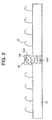
- FIGS. 1 and 2 schematically illustrate a top view and a cut end portion of a main embodiment according to the present invention, respectively.
- a fastener strip 10 having a flat substrate 11 and an engaging element 12 composed of many hook elements rising from an engaged surface of the substrate 11 further has a magnetic body 13 in a row, which rises from a surface of the substrate 11 and is disposed below substantially a center line of the fastener strip 10.
- the magnetic body 13 is composed of many magnetic projecting portions 13a made of a synthetic resin material in which magnetic particles 14 are mixed, and also in a raw material portion 13c of the substrate 11 below these projecting portions 13a, the above-mentioned magnetic particles 14 are mixed, and the magnetic particles 14 are not dispersed through the entire substrate 11. Accordingly, the magnetic body 13 becomes a continuous body in which valley portions 13b are formed between the projecting portions 13a.
- FIGS. 3 and 4 schematically illustrate another embodiment of the present invention.
- FIG. 3 is a top view of the fastener strip 10
- each row of the magnetic body 13 has magnetic particles 14 put inside the plural projecting portions 13a and each row of the magnetic body 13 is disposed at right and left side portions in a longitudinal direction of the fastener strip 10.
- FIG. 4 is a top view of the fastener strip 10, which rises from the surface of the substrate 11 and has the magnetic body 13 as a continuous projection, which is disposed below substantially a center line of the fastener strip 10.
- the other parts are identical with the main embodiment.
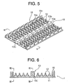
- FIGS. 5 to 8 specifically further illustrate other typical embodiments of the present invention.
- many engaging elements 12 are provided on a surface of a flat substrate 11 except for the both edges, and molded resin entering preventing walls 16 made of many wall portions 16a, which are arranged on a row along a longitudinal direction thereof, are disposed on the both edges , respectively.
- molded resin entering preventing walls 16 made of many wall portions 16a, which are arranged on a row along a longitudinal direction thereof, are disposed on the both edges , respectively.
- projecting portions 13a of a magnetic body 13 are disposed in a row at equal intervals and valley portions 13b are formed therebetween.
- the molded resin entering preventing walls 16, the substrate 11, the engage element 12, and the projecting portion 13a can be integrally molded and formed by a thermoplastic resin.
- the projecting portion 13a has a base raw material portion 13c at its base portion, and by the base raw material portion 13c, the projecting portions 13a are made into one continuous body.
- the base raw material portion 13c and the projecting portion 13a can be manufactured with integrally molded by a thermoplastic resin in which the magnetic particles are mixed.
- This wall portion 16a prevents a foam resin material 17 from entering the engaging element 12 of the fastener strip upon molding a foam, and at the same time, the wall portion 16a daringly makes a portion of the foam resin material 17 enter through a gap between the adjacent wall portions 16a to fix the wall portion 16a by the entered foam resin material 17 and the foam resin material 17 at the outside of the wall portion 16a. Thereby, it is possible to integrally fix the fastener strip 10 with the foam molded article more solidly.
- the wall portions 16a of respective rows are disposed in a staggered shape as shown in FIGS. 5 and 8, it is possible to increase a sealing function for preventing entering of the foam resin material.
- the foam resin material 17 having entered through the gap between the outside wall portions 16a bumps against the inside wall portion 16a to run round to a rear surface side of the outside wall portion 16a and then, a direction of the flow is changed.
- the height of the projecting portion 13a is the height of the wall portion 16a or less.
- the molded resin entering preventing walls 16 is a continuous wall, it is also necessary that the height of the projecting portion 13a is the height of the wall portion 16a or less.
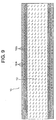
- FIGS. 9 to 12 are top views of the fastener strip 10 showing various arrangement figurations of the above-described molded resin entering preventing walls 16.
- the engaging elements 11 as plural hooks form a fastener layer covering most of the front surface of the fastener strip 10.
- the plural wall portions 16a are disposed along a width direction lateral edge of the fastener strip 10, and the above-described wall portions 16a are appropriately spaced such that the foam body can enter to a degree that is regulated in a molding process.
- These wall portions 16a can be made into the above-describe magnetic body, or if the other are of the substrate 11 has a magnetic body, the wall portions 16a are not necessarily be a magnetic body and they may be made only of the resin material that is identical with the substrate 11.
- the second row of the wall portions 16a namely, the second row from the edge of the fastener strip 10 can be partially viewed through a gap in the first row of the wall portions 16a.
- the wall portions 16a do not form a continuous wall along the lateral edge of the fastener strip, it is perceived that a predetermined flexibility can be maintained by the lateral edge. This flexibility has an advantage in making it possible to correspond the fastener strip 10 with a curved or concavo-convex metal mold surface, and further, making a seal function to prevent the engaging element from being contaminated possible.
- FIG. 9 illustrates an arrangement example such that intervals of the wall portions are different in a width direction of the fastener strip 10.
- two rows of wall portions 16a are disposed at the outside of three rows of the wall portions 16b with narrow intervals.
- the wall portions 16b with narrow intervals are configured in the same way as the wall portions 16a, however, due to the narrow intervals, there is less or no entering of the foam in the molding process. Accordingly, a combination of the wall portion 16a and the wall portion 16b makes it possible to realize both of fixing of the fastener strip 10 to the object to be molded and sealing for preventing contamination of the engaging element 11 shaped in a hook.
- FIG. 10 illustrates another arrangement example further having a lateral wall portion for sealing the edge of the fastener strip 10 so as to prevent entering of the foam and contamination of the engaging element.
- lateral wall portions 16c are disposed at longitudinal both edges of many groups of the engaging elements 3. Respective lateral wall portions 16c are continued and they are extended between the wall portions 16b with the narrow intervals, which are disposed at each edge of the fastener strip 10.
- FIG. 11 illustrates another arrangement example such that surrounding wall portions 16d surrounding a group of a plurality of hook-shaped engaging elements 12 of the fastener strip 10 are continuously provided so as to surround the engaging element group in a desired area.
- FIG. 12 illustrates that the wall portion at the second row is made into the continuous molded resin entering preventing wall 16. In this case, the continuous molded resin entering preventing wall 16 prevents the foam resin entered from the gap between the wall portions 16 of the first row from entering the engaging elements 12.
- FIG. 13 illustrates a constitutional example such that the surrounding wall portions 16d are arranged at predetermined intervals to surround the group of the engaging elements 12.
- the foam resin entering from the gap between the respective wall portions 16a composing the surrounding wall portion 16d is prevented from entering the engage elements 12 and further, the foam resin entering from the gap between the respective wall portions 16a is made to run round to a rear surface side of the respective wall portions 16a.
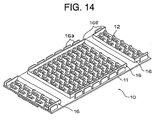
- FIG. 14 illustrates an example that is composed of a continuous surrounding wall portion 16e in place of the surrounding wall portions 16d shown in FIG. 13.
- only one row of the surrounding wall portions 16e surrounding the group of the engaging elements 12 is disposed, however, it is also possible to dispose two or more rows of the engaging elements 12.
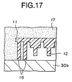
- FIGS. 15 to 18 show an example of a forming die upon integrally molding the above-described fastener strip 10 on a foam molded article and its molding mechanism.
- the magnetic body 13 is magnetically sucked to a magnet 31 that is disposed on a forming die 30 to position and fix the fastener strip 10 on the forming die 30.
- a force acts on the magnetic body 13, so that a force may act to allow the longitudinal both ends of the fastener strip 10 having this magnetic body 13 to correspond with the bipolar direction of the magnet 31.
- the magnetic body 13 has a narrow configuration extending to a longitudinal direction of the substrate 11 of the fastener strip 10, and the magnetic body 13 is configured so as to allow the longitudinal both ends of the fastener strip 10 to correspond with the bipolar direction of the magnet 31.
- FIGS. 19 to 28 show a modification example of the projecting portion 13a as the magnetic body and a configuration of a periphery of the projecting portion.
- FIG. 19 partially illustrates a configuration such that the base raw material portion 13c and the projecting portion 13a, which are made of a thermoplastic resin in which the magnetic particles 14 are mixed, are integrally fixed on the surface of the substrate 11.
- the base raw material portion 13c and the projecting portion 13a as the magnetic body 13 can be manufactured and fixed on the substrate 11 after molding the other constituent members of the fastener strip 10 separately.
- the magnetic body 13 may be manufactured continuously by superimposing the other constituent members of the fastener strip 10 on the magnetic body 13 while manufacturing this magnetic body 13.
- FIG. 20 partially illustrates a configuration such that a layer containing the magnetic particles 14 is laminated at a front end portion of the projecting portion 13a in the fastener strip 10 on which the projecting portion 13a is integrally molded.
- a thickness of a laminate layer 18 should be at a level whereby the magnetic body 13 according to the present invention can carry out its function.
- FIG. 21 shows an example such that a film 19 containing the magnetic powders 14 is formed in place of the laminate layer 18 made of the synthetic resin material containing the magnetic powders 14 shown in FIG. 20.
- the laminate layer 18 or the film 19 may be formed only at the front end portion of the projecting portion 13a.
- the laminate layer 18 or the film 19 may be formed across the entire surface of the projecting portion 13a.
- the laminate layer 18 or the film 19 may be formed only on an upper surface along a longitudinal direction including peaks and bottoms of the magnetic body 13.
- FIG. 22 shows an example of the continuous projecting portion 13a having no valley portion as the magnetic body 13.
- the magnetic body may be formed by using the thermoplastic resin material having the magnetic powders mixed therein, by forming the laminate layer as shown in FIGS. 20 and 21, and by forming the magnetic film.
- FIG. 23 shows an example such that two rows of the projecting portions 13a as the magnetic body 13.
- two rows of the projecting portions 13a are connected each other at the raw material portion 13c on the bottom surface, however, without connecting two rows, they may be separately formed.
- the thermoplastic plastic resin having the magnetic powders 14 mixed therein is used to mold the projecting portion 13 integrally, or the laminate layer containing the magnetic powders 14 may be formed, or the magnetic film may be formed. In this case, it is possible to appropriately adopt the above-described various methods for forming the magnetic body 13.
- FIG. 24 shows an example such that a portion of the engage element 12 is formed by the magnetic material in place of the projecting portion 13a upon forming the magnetic body 13.
- the two rows of the engaging elements 12 formed by the magnetic material do not disperse the magnetic force, its base raw material portion 13c is connected thereto, so that they are entirely configured as one narrow magnetic body 13.
- the base raw material portion 13c of the engaging elements 12 is not necessarily connected thereto and this engaging element row may be two or more.
- the engaging element row having the magnetic powders 14 mixed therein has both a function of the magnetic body 13 and an original engagement function of the engaging element 12.
- FIG. 26 shows an example such that the magnetic body 13 is composed of a metal wire material 20 as a long magnetic material that is disposed along the projecting portion 13a when the projecting portion 13a is composed of the continuous magnetic body 13.
- the metal wire material 20 with a circle cross section is disposed within the projecting portion 13a, however, in place of this, the metal wire material with a rectangular cross section or the other various cross sections may be adopted.
- a configuration such that the metal wire material 20 is exposed from the valley portion 13b that is formed between the projecting portions 13a can be also adopted.
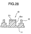
- FIG. 28 shows an example such that a long magnetic material is formed by a magnetic band material 21 disposed along an upper surface of the projecting portion 13a, for example, a magnetic metal wire material and a magnetic tape, or a woven and knitted fabric that is woven and composed from the synthetic resin fiber having a metal fiber and magnetic particles mixed therein or a nonwoven cloth made of these fibers.
- the magnetic band material 21 can be disposed inside the projecting portion 13a.
- the magnetic band material 21 may be adhered and secured on the upper surface of the projecting portion 13a, or upon molding the projecting portion 13a, the synthetic resin in the molten state enters a gap of the above-described fibers and runs round around the fibers to secure the magnetic band material 21.
- a magnetic string material made of the above-described fibers may be available.
- FIGS. 29 to 32 schematically illustrate a process for forming the fastener 10 and a device to be used in this process.
- a basic process for manufacturing a resin-based fastener strip through a combination of an extruding machine and a die/hole for formation is publicly known in the art. Accordingly, not an entire process but a portion of the process relevant to the present invention will be only described.
- FIG. 29 is a side view of a fastener strip extruding process, and in the drawing, an extruding machine 35 is disposed in adjacent to a die wheel 36.
- the die wheel 36 is made in a cylindrical shape and it has cavities 36a for molding hook-shaped engaging elements and cavities 36b for molding a magnetic body. Both cavities are further disposed along an outer periphery of the die wheel 36 as shown in FIG. 32 in detail.
- the extruding machine 35 has a narrow configuration that is extended across a diameter of a cylinder of the die wheel 36 and it includes a series of first passages (not shown) through which a resin 24 flows.
- a replenishment particle retention portion 37 is located on an upper surface of the extruding machine 35.
- a replenishment particle passage portion 37a (shown by a hidden line) connects the replenishment particle retention portion 37 to a replenishment particle nozzle 37b located on an extruding surface of the extruding machine 35 in adjacent to the die wheel 36.
- FIG. 30 is a front view of a die wheel facing surface of the extruding device 35.
- Many first nozzles 35a are extended across an extruding surface of the extruding machine 16 and the replenishment particle nozzle 37b is located substantially at a center of the extruding surface of the extruding machine 35.
- FIGS. 29 and 30 show that the replenishment particle retention portion 37 is displaced at a rear position above the extruding machine 35 and the replenishment particle passage portion 37a is located at a center within the extruding machine 35.
- a molted resin material 24 is extruded through the first passage of the extruding machine 35 and consequently, the first nozzle 35a.
- the die wheel 36 rotates in the anticlockwise direction, the molted resin material 24 is extruded through the first nozzle 35a, and the die wheel 36 continuously molds the fastener strip 10 having the engaging element 12 composed of the substrate 11 and a hook element in cooperation with the lower both surfaces of the extruding machine 35.
- the die wheel 36 continuously molds the fastener strip 10 having the engaging element 12 composed of the substrate 11 and a hook element in cooperation with the lower both surfaces of the extruding machine 35.
- a flow of a magnetic resin material 25 capable of being magnetically sucked and containing the magnetic powders 14 is extruded from the replenishment particle retention portion 37 through the replenishment particle passage portion 37a and the replenishment particle nozzle 37b.
- the magnetic resin material 25 capable of being magnetically sucked is extruded from the replenishment particle retention portion 37 to form a discontinuous portion of the substrate 11, and the replenishment particle nozzle 37b is positioned with the magnetic body molding cavity 36b so that the projecting portion 13 is formed on the substrate 11 by the magnetic body molding cavity 36b.
- the magnetic resin material 25 capable of being magnetically sucked is extruded to become an integral part of the fastener strip 10, however, it is found that the magnetic powders 14 remain in the discontinuous area and they are not dispersed over the entire substrate 11. Thereby, the fastener strip 10 having an area capable of being magnetically sucked as a discontinuous object is formed continuously to be pulled out from a peripheral portion of the bottom of the die wheel 36.
- FIG. 33 is a side cross sectional view showing an outline of an embodiment of another process such that the magnetic powders 14 do not pass through the extruding machine 35 unlike the main embodiment but they are directly introduced in the block molding cavity 23.
- the replenishment particle retention portion 37 is located at an appropriate position, and a flow of the resin 25 capable of being magnetically sucked is carried to the die wheel 36 through a line 26 in an area of the magnetic body molding cavity 36b.
- the resin 25 capable of being magnetically sucked is extruded to become an integral part of the fastener strip 10, however, the magnetic powders 14 remain in the discontinuous area and they are not dispersed over the entire substrate 11.
- the other procedures of the process are identical with those of the main embodiment.
- FIG. 34 is a cut end surface view showing an example of the fastener strip 10 that is manufactured by the embodiment in the process shown in FIG. 33.
- the magnetic particles 14 are only located in the center projecting portion 13a but they are not located in the substrate below a center block.
- a flow rate ratio of the resin 25 capable of being magnetically sucked in a relation with a flow rate ratio of the resin 24, a rotation velocity of the die wheel 21, and a degree of approximation of an outlet port of the line 26 to the magnetic body molding cavity 36b it is possible to control a width of the substrate 11 and a member to be carried together with the substrate 11.
- FIG. 34 is a cut end surface view showing an example of the fastener strip 10 that is manufactured by the embodiment in the process shown in FIG. 33.
- the magnetic particles 14 are only located in the center projecting portion 13a but they are not located in the substrate below a center block.
- a flow rate ratio of the resin 25 capable of being magnetically sucked in a relation with a flow rate ratio
- the present invention provides a very effective method to put the magnetic powders particularly in a target area of the fastener strip.
- the above descriptions may include many specific properties, however, these specific properties should not be interpreted as a limitation to a scope of the invention but they should be interpreted as an example of the embodiment. Other modifications are possible.
- the replenishment particle retention portion is not necessarily located at a rear position above the extruding machine unlike the main embodiment, but the replenishment particle retention portion may be located at another appropriate place, or the line or a tube to be used for carrying the magnetic powders to the replenishment particle passage.
- the resin containing the magnetic particles or such particles is extruded from the retention portion to the nozzle or the line outlet port through the passage or the line.
- a technique is publicly known in the art, and it includes a delivery by air or a fluid pressure, gravity or other means.
- the flow of the magnetic powders can run through a dedicated passage within the extruding machine or the flow of the magnetic powders can be coupled to another passage at an upstream of the nozzle within the extruding machine.
- the magnetic body is formed together with the substrate, or they can be put in the discontinuous area of the substrate to be formed separately.
- the magnetic powders can contain all ferromagnets including iron oxide of various configurations, iron stearate, various organic iron compounds, rare earth metal and rare earth metal compounds or other substances capable of being magnetically sucked in addition the above-described magnet bodies but not limited thereto.
- the magnetic powder can have a magnetic suction ability in itself.
- the magnetic powder itself becomes a magnet.
- the fastener strip can be secured to a metal or another substance capable of being sucked that is not a magnet in itself.
- the magnetic powders can be mixed in the resin in advance or the magnetic powders may be "loose" particles to be carried down in the resin flow.
- the configuration of the discontinuous magnetic body capable of being magnetically sucked may be different from the illustrated projecting portion, engaging element, and wall portion.
- a rectangular cube may be also used.
- the magnetic powders further can be only in the discontinuous area of the substrate.
- the discontinuous area of the substrate may be substantially flat having no member disposed thereon, or it may have a member disposed thereon.
- the engaging element disposed on the substrate may be different from a hook element fastener shown in the drawing. As an example, it may be a loop engaging element. As a matter of fact, the other type of engaging element (not merely a hook element or a loop) can be also used.
- the magnetic body can be injected not only in a center position shown in the main embodiment or a lateral position shown in FIG. 3 but also in the discontinuous area at arbitrary positions of the fastener strip.
- a hook element capable of being magnetically sucked can be formed on the substrate of the fastener strip.
- the fastener strip does not have one replenishment particle nozzle or one line outlet port but the replenishment particle nozzles can be disposed at plural places on the surface of the extruding machine, or the line outlet ports can be disposed at plural places in the vicinity of the die wheel. As a matter of facet, such plural arrangements result in the fastener strip shown in FIG. 3
- the magnetic powders are not introduced through the replenishment particle nozzle as the main embodiment shown in FIG. 31 or they are not directly introduced in the block molding cavity but they can be introduced in a flow of the resin in the discontinuous area right above the resin after being extruded from the first nozzle.
- FIGS. 35(A), 35(B), and 36 illustrate a device for manufacturing a fastener strip and a method for manufacturing the same according to another embodiment of the present invention.
- FIG. 35 shows that the fastener strip is manufactured in two steps.
- a first die wheel 45 is disposed facing to an extruding port 40a of a first extruding die 40.
- the first die wheel 45 rotates around a rotational axis in a vertical direction to the paper in FIG. 35(A).
- a magnetic body molding cavity is formed on a peripheral surface of rotation of the first die wheel 45.
- concave portions 45a for projecting portions having narrow configurations are formed, which are intermittently disposed in a peripheral direction.
- a clearance is formed between the first extruding die 40 and the first die wheel 45, and in this clearance, the base raw material portion 13c of the magnetic body 13 is molded as shown in FIG. 6.
- the concave portions 45a for projecting portions can be continuously formed in a peripheral direction of the first die wheel 45.
- a second die wheel 46 is disposed facing to an extruding port 41a of a second extruding die 41.
- the second die wheel 46 rotates around a rotational axis in a vertical direction to the paper in FIG. 35 (B).
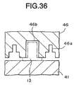
- a fastener strip molding cavity is formed on a peripheral surface of rotation of the second die wheel 46.
- concave portions for engaging elements and concave portions for molding a substrate which are disposed at predetermined intervals in a peripheral direction, a fastener strip molding cavity 46a, a concave portion 46b for accommodating a magnetic molded article, a concave portion for a member composing the fastener strip including the other parts, and a concave portion such as the above-described wall for preventing entering of a molded material, the wall portion and the like (not shown) are formed according to need.
- the synthetic resin 25 displaced in the first extruding die 40 in the molten state having the magnetic powders mixed therein is extruded from the extruding port 40a, and this synthetic resin 24 is continuously filled in the fastener strip molding cavity 46a of the first die wheel 45 rotating around a horizontal axis.
- the magnetic body 13 (the molded article) having the projecting portion 13a and the base raw material portion 13c is peeled off from the first die wheel 45.
- the synthetic resin 24 displaced in the second extruding die 41 in the molten state having the magnetic powders mixed therein is extruded from the extruding port 41a, and this synthetic resin 24 is continuously filled in the fastener strip molding cavity of the second die wheel 46 rotating around a horizontal axis.
- the magnetic body molded article 13 that is molded in the above through a magnetic material guide portion 47 is continuously supplied to the concave portion 46b for accommodating a magnetic molded article in the fastener strip molding cavity.
- the fastener strip molded article including the substrate 11, the engaging element 12, and the projecting portion 13a is peeled off so as to manufacture the fastener strip 10.
- the manufactured fastener strip 10 can be used as cut in a desired length.
- the cross sectional figuration of the concave portion 46b for accommodating a magnetic molded article formed in the above-described second die wheel 46 is made larger than the cross sectional figuration of the above-described magnetic body 13 molded separately, particularly, the cross sectional figuration of its projecting portion 13a.
- the resin for molding 24 of the fastener strip 10 is covered with the resin for molding 24 of the fastener strip 10.
- the synthetic resin 25 in the molten state having the magnetic powders mixed therein is extruded from the extruding port 40a of the first extruding die 40.
- the fastener strip 10 also can be manufactured by extruding the synthetic resin having no magnetic poser mixed therein from the extruding port 40a, supplying a long magnetic material 22 separately prepared through a magnetic body guide portion 48 to mold the magnetic body molded article 13 as the magnetic body, and supplying this magnetic body molded article 13 through a magnetic body guide portion 47 disposed at the upstream side of a rotational direction of the second die wheel 46 shown in FIG. 35(B).
- FIG. 37(A) illustrates a configuration such that the magnetic body guide portion 48 is provided at the outside of the extruding die 40
- FIG. 37(B) illustrates an example such that the magnetic body guide portion 48 is formed within the extruding die 40.
- the other constitutional members are identical with those in FIG. 37(A).
- the fastener strip 10 is manufactured in one step.
- the above-mentioned extruding die 41 is used independently to manufacture the fastener strip 10 with a magnetic body.
- the extruding ports 40a and 41a are disposed at the upper and lower positions of the extruding die 41, its explanation is herein omitted and the same reference numerals are given to the same components.
- Two extruding ports 40a and 41a disposed at the extruding die 41 can extrude the different synthetic resin members, respectively. As shown in FIG.
- a nozzle portion 40a-1 and a concave portion 40a-2 are formed at a front end of the extruding port 40a.
- This concave portion 40a-2 is formed so as to intensively mix the magnetic body from the extruding port 40a into the narrow concave portion for the projecting portion, which is formed for forming the magnetic body and is continuously or intermittently disposed in a peripheral direction, and fill the synthetic resin in the molten state therein.
- the extruding ports 41a at a lower position is formed to be adjusted to respective concave portions corresponding to the fastener strip molding cavity 46a that is formed in the die wheel 46, for example, the cavity for the projecting portion, the cavity for the engaging element and the like.
- a nozzle portion 41a-1 and a concave portion 41a-2 around the nozzle portion 41a-1 are formed at a front end of the extruding port 41a.
- the synthetic resin 24 extruded from the nozzle portion 41a-1 may spread over the concave portion 41a-2 and the synthetic resin 24 can be filled from the entire surface of the fastener strip molding cavity 46b.
- the magnetic resin material 25 in the molten state having the magnetic powders mixed therein is extruded from the extruding outlet port 40a to be continuously filled in the magnetic body molding cavity. Thereby, the magnetic body is manufactured.
- the synthetic resin material 24 in the molten state is extruded from the extruding port 41a to be continuously filled within the fastener strip molding cavity 46a.
- the synthetic resin material 24 from the extruding ports 41a as shown in FIG. 19, the magnetic body 13 made of the magnetic resin material 25 from the extruding outlet port 40a is superimposed on the substrate 11 so that the magnetic body 13 can be integrated with the substrate 11.
- the synthetic resin material 24 can be filled in such a manner that the magnetic body 13 and the substrate are connected in a strip width direction.
- a continuous fastener strip can be obtained. This continuous fastener strip can be used as cut into a desired length.
- the synthetic resin 24 having no magnetic powder mixed therein is extruded from the extruding port 40a to be filled in the fastener strip molding cavity 46a and the magnetic body molding cavity 46b (in this case, the concave portion for molding the magnetic body and the concave portion for molding the fastener strip).
- the magnetic body provided with the long magnetic material 22 is formed in the projecting portion 13a. Thereafter, the fastener strip molded article is peeled off from the die wheel to manufacture the fastener strip 10.
- the fastener strip 10 is molded and by laminating or coating the magnetic material at least on the upper surface of the projecting portion 13a in the molded fastener strip molded article, the magnetic body can be also formed.
- the fastener strip can be manufactured. In this time, it is necessary that the continuously molded fastener strip is cut between the adjacent projecting portions and the fastener strip element is created. After cutting the fastener strip or before cutting the fastener strip, the above-described magnetic member can be applied at least on the upper surface of the projecting portion.
- FIGS. 35 to 39 are typical embodiments and any device and method for manufacturing a fastener strip may be adopted if they are within a scope of the present invention. Accordingly, the scope of the present invention should be decided not by the illustrated embodiments but by attached claims and the legally equivalents for the claims.
Landscapes
- Engineering & Computer Science (AREA)
- Mechanical Engineering (AREA)
- Manufacturing & Machinery (AREA)
- Aviation & Aerospace Engineering (AREA)
- Transportation (AREA)
- Slide Fasteners, Snap Fasteners, And Hook Fasteners (AREA)
- Purses, Travelling Bags, Baskets, Or Suitcases (AREA)
- Moulds For Moulding Plastics Or The Like (AREA)
- Extrusion Moulding Of Plastics Or The Like (AREA)
- Molding Of Porous Articles (AREA)
- Physical Vapour Deposition (AREA)
Abstract
Description
Claims (40)
- A fastener strip capable of being magnetically fixed on an object, being characterized by comprising:(a) a substrate;(b) at least one engaging element to be supported on the substrate; and(c) a magnetic body put into a discontinuous area of the substrate or into a discontinuous area of at least one integrated member to be supported on the substrate.
- The fastener strip according to claim 1, being characterized in that the magnetic body has a narrow configuration that is extended in a longitudinal direction of the substrate and depending on a magnet disposed at a predetermined position of the object, the magnetic body has a sufficient magnetism for allowing the longitudinal ends of the fastener strip to correspond with a bipolar direction of the magnet.
- The fastener strip according to claim 1 or 2, being characterized in that the magnetic body is disposed in the discontinuous area of the substrate along its longitudinal direction.
- The fastener strip according to claim 2, being characterized in that the magnetic body is disposed substantially in a lateral center of the discontinuous area of the substrate along a longitudinal direction thereof, the magnetic body comprising a single strip of projecting portions.
- The fastener strip according to claim 4, being characterized in that valley portions are formed at equal intervals along the longitudinal direction of the substrate between the projecting portions.
- The fastener strip according to claim 1, comprising at least one row of entering preventing walls for preventing a foam resin from entering the area on which the engaging element is supported from the outside at the both lateral side edges of the substrate.
- The fastener strip according to claim 6, being characterized in that at least two rows of the entering preventing walls are disposed at the both lateral side edges of the substrate in a longitudinal direction thereof, the preventing wall for each row is composed of a plurality of preventing wall portions that are disposed in a row at predetermined intervals, and the preventing wall portions of the adjacent entering preventing walls are disposed in a staggered shape with each other.
- The fastener strip according to claim 4 or 7, being characterized in that the magnetic body is made of a synthetic resin material containing magnetic materials.
- The fastener strip according to claim 4 or 7, being characterized in that the magnetic body is included in the substrate.
- The fastener strip according to claim 8, being characterized in that the magnetic material comprises magnetic powders.
- The fastener strip according to claim 8, being characterized in that the magnetic material comprises a long magnetic material.
- The fastener strip according to claim 11, being characterized in that a valley portion is formed in the projecting portion, the long magnetic material is embedded in the projecting portion, and the long magnetic material is exposed at the valley portion.
- The fastener strip according to claim 11, being characterized in that the long magnetic material is fixed on an upper surface of the projecting portion.
- The fastener strip according to claim 4, being characterized in that the projecting portion comprises a plurality of engaging elements, which contain the magnetic material and of which substrates are connected to one another.
- The fastener strip according to claim 8, being characterized in that the projecting portion includes a thermoplastic resin to be integrally molded on the substrate.
- The fastener strip according to claim 6, being characterized in that at least one row of the preventing wall portions comprises a continuous wall portion.
- The fastener strip according to claim 1, being characterized in that the engaging element has many engaging element areas that are disposed on one surface of the substrate and the engaging element areas are defined in a longitudinal direction through partition walls.
- The fastener strip according to claim 1, being characterized in that the partition walls are disposed at intervals along its longitudinal direction.
- The fastener strip according to claim 17, being characterized in that each engaging element area defined by the partition wall comprises a surrounding wall portion surrounding the engaging element area including the partition wall.
- The fastener strip according to claim 6, being characterized in that the magnetic body includes at least one row of entering preventing walls.
- A method for manufacturing a fastener strip capable of being magnetically fixed to an object, being characterized by comprising the steps of:(a) disposing a magnetic powder substance; and(b) injecting the magnetic powder substance into a discontinuous area of a substrate layer of the fastener strip or into a discontinuous area that is provided with at least one integrated member to be carried on the substrate layer of the fastener strip.
- The method according to claim 21, being characterized in that the step of injecting the magnetic powder substance comprises a step of extruding a plastic resin through an extruding machine and introducing the magnetic powder substance through another passage in the extruding machine.
- The method according to claim 22, being characterized in that the another passage has an outlet port that is disposed on substantially a center of a front surface of the extruding machine.
- The method according to claim 22, being characterized in that the step of introducing the magnetic powder substance includes extruding a mixture of the plastic resin and the magnetic powder substance through the another passage in the extruding machine.
- The method according to claim 21, being characterized in that the step of injecting the magnetic powder substance includes a step of extruding the plastic resin through the extruding machine and extruding the magnetic powder substance to a die wheel in adjacent to the extruding machine through another line.
- The method according to claim 25, being characterized in that the another line has an outlet port that is disposed in the vicinity of a molding cavity in the die wheel.
- The method according to claim 26, being characterized in that the molding cavity is disposed on substantially a center of a peripheral surface of the die wheel.
- The method according to claim 25, being characterized in that the step of introducing the magnetic powder substance includes extruding a mixture of the plastic resin and the magnetic powder substance to the die wheel through the another passage.
- A device for manufacturing a fastener strip having a magnetic body, characterized by comprising:wherein the magnetic body molding cavity includes concave portions for projecting portions having narrow configurations, which are continued in a peripheral direction or are intermittently disposed, anda magnetic body molding portion having a first extruding die, in which magnetic powders are mixed and which has an extruding port for extruding a synthetic resin material in a molten state, and a first die wheel, which rotates around a horizontal axis as facing to the extruding port and has a magnetic body molding cavity that is formed along a periphery surface of the rotational direction; anda fastener strip molding portion having a second extruding die having an extruding port for extruding a synthetic resin material in a molted state, a second die wheel, which rotates around a horizontal axis as facing to the extruding port and has a fastener strip molding cavity that is formed along a periphery surface in the rotational direction, and a magnetic body guide portion, which is located at an upstream side in a rotational direction of the second die wheel for the second extruding die and guides a magnetic molded article that is molded by the magnetic body molding portion to a predetermined position in the fastener strip molding cavity,
the fastener strip molding cavity includes concave portions for engaging elements that are disposed at a predetermined pitch in a peripheral direction thereof, and concave portions for accommodating the magnetic molded article that are molded by the magnetic body molding portion. - A method for manufacturing a fastener strip capable by using the fastener strip manufacturing device according to claim 29, being characterized by comprising the steps of:extruding a synthetic resin material having magnetic powders mixed therein in a molten state from an extruding port of a first extruding die, and continuously filling the synthetic resin material in the magnetic body molding cavity while rotating the first die wheel;peeling off a magnetic body molded article from a peripheral surface of the first die wheel;extruding a synthetic resin material in a molten state from an extruding port of a second extruding die, and continuously filling the synthetic resin material in the fastener strip molding cavity while rotating the second die wheel;continuously supplying the magnetic body molded article to the concave portion for accommodation in the fastener strip molding cavity through the magnetic body guide portion;integrally welding the synthetic resin material with the magnetic body molded article; andpeeling off a fastener strip molded article including the engaging element and a magnetic body having a narrow configuration from the second die wheel.
- A device for manufacturing a fastener strip having a magnetic body, characterized by comprising:wherein the magnetic body molding cavity includes concave portions for projecting portions having narrow configurations, which are continued in a peripheral direction or are intermittently disposed, anda magnetic body molding portion having a first extruding die having an extruding port for extruding a synthetic resin material in a molten state, a first die wheel which rotates around a horizontal axis as facing to the extruding port and has a magnetic body molding cavity that is formed along a periphery surface of the rotational direction, and a magnetic body guide portion which is located at an upstream side in a rotational direction of the first die wheel for the first extruding die and guides a long magnetic material to a predetermined position in a concave portion for projecting portion in the magnetic body molding cavity;a fastener strip molding portion having a second extruding die having an extruding port for extruding a synthetic resin in a molted state, a second die wheel which rotates around a horizontal axis as facing to the extruding port and has a fastener strip molding cavity that is formed along a periphery surface of the rotational direction, and a magnetic body guide portion which is located at an upstream side in a rotational direction of the second die wheel for the second extruding die and guides a magnetic molded article molded by the magnetic body molding portion to a predetermined position in the fastener strip molding cavity,
the fastener strip molding cavity includes concave portions for engaging elements that are disposed at a predetermined pitch in a peripheral direction thereof, and concave portions for accommodating the magnetic molded article that are molded by the magnetic body molding portion. - The device for manufacturing a fastener strip according to claim 31, being characterized in that a long magnetic material guide portion is formed in the first extruding die.
- A method for manufacturing a fastener strip capable by using the fastener strip manufacturing device according to claim 31 or 32, being characterized by comprising the steps of:extruding a synthetic resin material in a molten state from an extruding port of a first extruding die, and continuously filling the synthetic resin material in the magnetic body molding cavity while rotating the first die wheel;continuously supplying a long magnetic material to a predetermined position of the concave portion for projecting portion through the magnetic body guide portion;integrally coupling the synthetic resin material with the long magnetic material;peeling off a magnetic body molded article from a peripheral surface of the first die wheel;extruding a synthetic resin material in a molten state from an extruding port of a second extruding die, and continuously filling the synthetic resin material in the fastener strip molding cavity that is formed in the second die wheel;continuously supplying the magnetic body molded article to the concave portion for accommodation in the fastener strip molding cavity through the magnetic body guide portion;integrally welding the synthetic resin material with the magnetic body molded article; andpeeling off a fastener strip molded article including the engaging element and a magnetic body having a narrow configuration from the second die wheel.
- A device for manufacturing a fastener strip having a magnetic body, characterized by comprising:wherein the magnetic body molding cavity includes concave portions for projecting portions having narrow configurations, which are continued in a peripheral direction or are intermittently disposed, and the fastener strip molding cavity includes concave portions for engaging elements that are disposed at a predetermined pitch in a peripheral direction thereof,an extruding die having a pair of extruding ports for extruding a synthetic resin material in a molten state separately; and a die wheel which rotates around a horizontal axis as facing to the extruding port and has a magnetic body molding cavity and a fastener strip molding cavity that are formed along a periphery surface of the rotational direction,
the pair of extruding ports is formed on the extruding die on upper and lower positions along a rotational direction of the die wheel,
the extruding port at the upper position is formed in a shape so as to locally extrude a synthetic resin having magnetic powders mixed therein and in a molten state to the magnetic body molding cavity, and
the extruding port at the lower position is formed in a shape so as to extrude a synthetic resin in a molten state to the fastener strip molding cavity. - A method for manufacturing a fastener strip capable by using the fastener strip manufacturing device according to claim 34, being characterized by comprising the steps of:extruding a synthetic resin material having magnetic powders mixed therein and in a molten state from the extruding port at the upper position, and continuously filling the synthetic resin material in the magnetic body molding cavity while rotating the die wheel;extruding a synthetic resin material in a molten state from the extruding port at the lower position, and continuously filling the synthetic resin material in the fastener strip molding cavity while rotating the die wheel; andpeeling off a fastener strip molded article including an engaging element and a magnetic body having a narrow configuration from the die wheel.
- A device for manufacturing a fastener strip having a magnetic body, characterized by comprising:wherein the magnetic body molding cavity includes concave portions for projecting portions having narrow configurations, which are continued in a peripheral direction or are intermittently disposed, and the magnetic body molding cavity includes concave portions for engaging elements that are disposed at a predetermined pitch in a peripheral direction thereof, anda magnetic body molding portion having an extruding die having an extruding port for extruding a synthetic resin material in a molten state, a die wheel which rotates around a horizontal axis as facing to the extruding port and has a magnetic body molding cavity and a fastener strip molding cavity that are formed along a periphery surface of the rotational direction, and a magnetic body guide portion which is located at an upstream side in a rotational direction of the die wheel for the extruding die and guides a long magnetic material to a predetermined position in the magnetic body molding cavity,
the magnetic material guide portion is formed in a shape so as to direct the long magnetic material to a predetermined position of the concave portion for projecting portion. - The device for manufacturing a fastener strip according to claim 36, being characterized in that the magnetic material guide portion is formed in the extruding die.
- A method for manufacturing a fastener strip capable by using the fastener strip manufacturing device according to claim 36 or 37, being characterized by comprising the steps of:extruding a synthetic resin material in a molten state from the extruding port, and continuously filling the synthetic resin material in the magnetic body molding cavity and the fastener strip molding cavity while rotating the die wheel;continuously supplying a long magnetic material to a predetermined position of the concave portion for projecting portion through the magnetic body guide portion;integrally coupling the synthetic resin material with the long magnetic material; andpeeling off a fastener strip molded article including the engaging element and a magnetic body having a narrow configuration from the die wheel.
- A method for manufacturing a fastener strip having a magnetic body, being characterized by comprising the steps of:preparing an extruding die having an extruding port for extruding a synthetic resin material in a molten state;preparing a die wheel which rotates around a horizontal axis as facing to the extruding port and has a magnetic body molding cavity and a fastener strip molding cavity that are formed along a periphery surface of the rotational direction;preparing the die wheel wherein the magnetic body molding cavity includes concave portions for projecting portions having narrow configurations, which are continued in a peripheral direction or are intermittently disposed, and the fastener strip molding cavity includes concave portions for engaging elements that are disposed at a predetermined pitch in a peripheral direction thereof;extruding a synthetic resin material in a molten state from the extruding port of the extruding die and continuously filling the synthetic resin material in the molding cavities while rotating the die wheel;peeling off a fastener strip molded article including the engaging element and a projecting portion having a narrow configuration from the die wheel; andlaminating a layer containing magnetic powders or applying coating containing magnetic powders on at least an upper surface of the projecting portion.
- A method for manufacturing a fastener strip having a magnetic body, being characterized by comprising the steps of:preparing an extruding die having an extruding port for extruding a synthetic resin material in a molten state;preparing a die wheel which rotates around a horizontal axis as facing to the extruding port and has a magnetic molding cavity and a fastener strip molding cavity that are formed along a periphery surface of the rotational direction;preparing the die wheel wherein the magnetic body molding cavity includes concave portions for projecting portions having narrow configurations, which are disposed in a peripheral direction of a peripheral surface of the die wheel at equal intervals and are continued in a die wheel axial direction or are intermittently disposed, and the fastener strip molding cavity includes concave portions for engaging elements that are disposed at a predetermined pitch in a peripheral direction thereof;extruding a synthetic resin material in a molten state from the extruding port of the extruding die and continuously filling the synthetic resin material in the molding cavities while rotating the die wheel;peeling off a fastener strip molded article including the engaging element and a projecting portion having a narrow configuration from the die wheel;laminating a layer containing magnetic powders or applying coating containing magnetic powders on at least an upper surface of the projecting portion; andcutting the fastener strip molded article between the adjacent projecting portions in the peripheral direction.
Applications Claiming Priority (5)
| Application Number | Priority Date | Filing Date | Title |
|---|---|---|---|
| US09/971,512 US7022394B2 (en) | 2001-05-04 | 2001-10-05 | Fastener strip with discrete magnetically attractable area, and method and apparatus of making same |
| US09/972,353 US6720059B2 (en) | 2001-05-04 | 2001-10-05 | Fastener strip having vertical sealing members l |
| US972353 | 2001-10-05 | ||
| US971512 | 2001-10-05 | ||
| PCT/JP2002/006848 WO2003030672A1 (en) | 2001-10-05 | 2002-07-05 | Fastener strip with magnetic body, and method and device for manufacturing the fastener strip |
Publications (3)
| Publication Number | Publication Date |
|---|---|
| EP1452106A1 true EP1452106A1 (en) | 2004-09-01 |
| EP1452106A4 EP1452106A4 (en) | 2007-07-11 |
| EP1452106B1 EP1452106B1 (en) | 2011-12-21 |
Family
ID=27130547
Family Applications (1)
| Application Number | Title | Priority Date | Filing Date |
|---|---|---|---|
| EP02745864A Expired - Lifetime EP1452106B1 (en) | 2001-10-05 | 2002-07-05 | Fastener strip with magnetic body |
Country Status (8)
| Country | Link |
|---|---|
| EP (1) | EP1452106B1 (en) |
| JP (1) | JP3886965B2 (en) |
| KR (1) | KR100540997B1 (en) |
| CN (1) | CN1250128C (en) |
| AU (1) | AU2002318624B2 (en) |
| BR (1) | BRPI0213677B1 (en) |
| ES (1) | ES2377558T3 (en) |
| WO (1) | WO2003030672A1 (en) |
Cited By (9)
| Publication number | Priority date | Publication date | Assignee | Title |
|---|---|---|---|---|
| EP1726230A1 (en) * | 2005-05-27 | 2006-11-29 | Aplix | Foam mold assembly comprising an insert with fixing means |
| EP1726229A1 (en) | 2005-05-27 | 2006-11-29 | Aplix | Insert with barrier members for foam moulding |
| ES2396832R1 (en) * | 2009-06-17 | 2013-03-19 | Ykk Corp | MOLDED MALE SURFACE HOLDING ELEMENT |
| US8512845B2 (en) | 2008-11-06 | 2013-08-20 | Ykk Corporation | Molded male surface fastener |
| WO2014120931A1 (en) * | 2013-01-31 | 2014-08-07 | Johnson Controls Technology Company | Sheet material attachment system and method |
| WO2015091265A1 (en) * | 2013-12-18 | 2015-06-25 | Velcro Industries B.V. | Mold-in touch fastening product |
| US9357815B2 (en) | 2011-10-26 | 2016-06-07 | Ykk Corporation | Molded surface fastener |
| EP3050746A1 (en) * | 2011-12-13 | 2016-08-03 | Velcro Bvba | Mold-in touch fastening product |
| DE102010029377B4 (en) * | 2010-01-12 | 2018-11-15 | Taiwan Paiho Limited | Fastening tape assembly and foam body containing them |
Families Citing this family (27)
| Publication number | Priority date | Publication date | Assignee | Title |
|---|---|---|---|---|
| WO2010016122A1 (en) * | 2008-08-06 | 2010-02-11 | Ykk株式会社 | Molded hook surface fastener |
| JP5496797B2 (en) * | 2010-07-05 | 2014-05-21 | 横浜ゴム株式会社 | Pneumatic tire |
| ES2593609T3 (en) | 2010-08-23 | 2016-12-12 | Ykk Corporation | Molding hook and loop fixing device |
| CN104757749B (en) * | 2010-08-23 | 2017-06-23 | Ykk株式会社 | Forming face slide fastener |
| CN103648318B (en) * | 2011-07-05 | 2016-02-03 | Ykk株式会社 | The manufacture method of shaping magic tape and shaping magic tape and the manufacture method of buffer body |
| CN103190744B (en) * | 2013-03-27 | 2015-12-02 | 福建浔兴拉链科技股份有限公司 | A kind of magnet therapeutic zipper belt and manufacture craft thereof |
| JP5709953B2 (en) * | 2013-09-19 | 2015-04-30 | Ykk株式会社 | Manufacturing method of molded surface fastener |
| JP6161789B2 (en) | 2014-03-13 | 2017-07-12 | Ykk株式会社 | Molded surface fastener, cushion body, cushion body manufacturing method, and molding die |
| WO2016002049A1 (en) * | 2014-07-03 | 2016-01-07 | Ykk株式会社 | Molded surface fastener and cushion body |
| KR101889641B1 (en) * | 2014-07-03 | 2018-08-17 | 와이케이케이 가부시끼가이샤 | Molded surface fastener and molded surface fastener manufacturing method |
| JP5994874B2 (en) * | 2015-01-30 | 2016-09-21 | 横浜ゴム株式会社 | Pneumatic tire and manufacturing method thereof |
| CN105982395A (en) * | 2015-02-26 | 2016-10-05 | 台湾百和工业股份有限公司 | Fastening tape for foaming material and foaming material comprising same |
| US9138032B1 (en) | 2015-04-28 | 2015-09-22 | Velcro Industries B.V. | Mold-in touch fastener systems with wave-shaped wall |
| US9635910B2 (en) * | 2015-04-28 | 2017-05-02 | Velcro BVBA | Mold-in touch fastener systems with wave-shaped wall |
| JP6438347B2 (en) | 2015-05-12 | 2018-12-12 | Ykk株式会社 | Molded surface fastener |
| US10548374B2 (en) | 2015-07-17 | 2020-02-04 | Ykk Corporation | Fastening tape with flexibility in the longitudinal direction and associated methods |
| US10189387B2 (en) | 2015-07-17 | 2019-01-29 | Ykk Corporation | Fastening tape with flexibility in the lateral direction and associated methods |
| CN105455322B (en) * | 2016-01-19 | 2018-06-05 | 江苏盛业拉链科技有限公司 | A kind of Novel zipper processing and sorting device |
| US10051926B2 (en) * | 2016-02-08 | 2018-08-21 | Ykk Corporation | Fastening tape with injected foam gasket |
| WO2017141436A1 (en) * | 2016-02-19 | 2017-08-24 | Ykk株式会社 | Molded surface fastener |
| WO2017141435A1 (en) * | 2016-02-19 | 2017-08-24 | Ykk株式会社 | Molded surface fastener |
| JP6732374B2 (en) * | 2016-04-13 | 2020-07-29 | Ykk株式会社 | Molded surface fastener |
| US10362839B2 (en) * | 2017-08-22 | 2019-07-30 | Ykk Corporation | Slide fastener |
| US10743597B2 (en) * | 2018-01-11 | 2020-08-18 | Wai Chi TONG | Magnetic self-zipping zipper with different magnetic pull-in forces |
| CN109900462B (en) * | 2019-03-07 | 2020-12-01 | 温州博辉新材料科技有限公司 | A smart wearable zipper durability detection device |
| JP7123990B2 (en) * | 2019-04-17 | 2022-08-23 | Ykk株式会社 | fastening tape |
| WO2022102546A1 (en) * | 2020-11-10 | 2022-05-19 | クラレファスニング株式会社 | Male molded hook-and-loop fastener |
Family Cites Families (8)
| Publication number | Priority date | Publication date | Assignee | Title |
|---|---|---|---|---|
| JPS6364218U (en) * | 1986-10-17 | 1988-04-27 | ||
| JPH0542010A (en) * | 1991-08-17 | 1993-02-23 | Fumiko Ishida | Fastener |
| US5945193A (en) * | 1995-12-06 | 1999-08-31 | Velcro Industries B.V. | Touch fastener with porous metal containing layer |
| US6106051A (en) * | 1998-12-16 | 2000-08-22 | Miskowic; Michael J. | Truck bed cover |
| DE19956011A1 (en) * | 1999-11-20 | 2001-06-21 | Binder Gottlieb Gmbh & Co | Fastener part |
| US6596371B1 (en) | 2000-01-19 | 2003-07-22 | Aplix, Inc. | Component for overcasting for a moulded object |
| JP3699896B2 (en) * | 2000-06-30 | 2005-09-28 | Ykk株式会社 | Seat fasteners |
| US6468624B1 (en) * | 2000-11-20 | 2002-10-22 | Ykk Corporation Of America | Fastener strip with magnetic attractant |
-
2002
- 2002-07-05 EP EP02745864A patent/EP1452106B1/en not_active Expired - Lifetime
- 2002-07-05 JP JP2003533716A patent/JP3886965B2/en not_active Expired - Lifetime
- 2002-07-05 AU AU2002318624A patent/AU2002318624B2/en not_active Ceased
- 2002-07-05 ES ES02745864T patent/ES2377558T3/en not_active Expired - Lifetime
- 2002-07-05 KR KR1020047004903A patent/KR100540997B1/en not_active Expired - Lifetime
- 2002-07-05 CN CNB02819649XA patent/CN1250128C/en not_active Expired - Lifetime
- 2002-07-05 WO PCT/JP2002/006848 patent/WO2003030672A1/en not_active Ceased
- 2002-07-05 BR BRPI0213677A patent/BRPI0213677B1/en not_active IP Right Cessation
Cited By (13)
| Publication number | Priority date | Publication date | Assignee | Title |
|---|---|---|---|---|
| EP1726230A1 (en) * | 2005-05-27 | 2006-11-29 | Aplix | Foam mold assembly comprising an insert with fixing means |
| EP1726229A1 (en) | 2005-05-27 | 2006-11-29 | Aplix | Insert with barrier members for foam moulding |
| FR2886109A1 (en) * | 2005-05-27 | 2006-12-01 | Aplix Sa | SURFACE MOLDED WITH ANTI INTRUSION |
| FR2886200A1 (en) * | 2005-05-27 | 2006-12-01 | Aplix Sa | MOLD-OVER-MOLDING ASSEMBLY WITH ANTI-REMOTE ACTION |
| CN1871968B (en) * | 2005-05-27 | 2011-01-26 | 雅柏利公司 | Overmould with anti-intrusion ribs |
| US8512845B2 (en) | 2008-11-06 | 2013-08-20 | Ykk Corporation | Molded male surface fastener |
| ES2396832R1 (en) * | 2009-06-17 | 2013-03-19 | Ykk Corp | MOLDED MALE SURFACE HOLDING ELEMENT |
| DE102010029377B4 (en) * | 2010-01-12 | 2018-11-15 | Taiwan Paiho Limited | Fastening tape assembly and foam body containing them |
| US9357815B2 (en) | 2011-10-26 | 2016-06-07 | Ykk Corporation | Molded surface fastener |
| US9781979B2 (en) | 2011-10-26 | 2017-10-10 | Ykk Corporation | Molded surface fastener |
| EP3050746A1 (en) * | 2011-12-13 | 2016-08-03 | Velcro Bvba | Mold-in touch fastening product |
| WO2014120931A1 (en) * | 2013-01-31 | 2014-08-07 | Johnson Controls Technology Company | Sheet material attachment system and method |
| WO2015091265A1 (en) * | 2013-12-18 | 2015-06-25 | Velcro Industries B.V. | Mold-in touch fastening product |
Also Published As
| Publication number | Publication date |
|---|---|
| JPWO2003030672A1 (en) | 2005-01-20 |
| BR0213677A (en) | 2004-10-26 |
| KR20040048927A (en) | 2004-06-10 |
| AU2002318624B2 (en) | 2005-10-20 |
| EP1452106A4 (en) | 2007-07-11 |
| CN1564663A (en) | 2005-01-12 |
| JP3886965B2 (en) | 2007-02-28 |
| EP1452106B1 (en) | 2011-12-21 |
| WO2003030672A1 (en) | 2003-04-17 |
| KR100540997B1 (en) | 2006-01-10 |
| ES2377558T3 (en) | 2012-03-28 |
| CN1250128C (en) | 2006-04-12 |
| BRPI0213677B1 (en) | 2016-12-06 |
Similar Documents
| Publication | Publication Date | Title |
|---|---|---|
| AU2002318624B2 (en) | Fastener strip with magnetic body, and method and device for manufacturing the fastener strip | |
| US6896759B2 (en) | Fastener strip with discrete magnetically attractable area, and method and apparatus of making same | |
| US9445650B2 (en) | Male surface fastener member for use in a cushion body mold and manufacturing method thereof | |
| EP2342989B1 (en) | Molded male surface fastener | |
| JP6732374B2 (en) | Molded surface fastener | |
| GB2410528A (en) | Surface fastener with side and cross barriers | |
| US9936773B2 (en) | Molded hook and loop fastener and method of manufacturing cushion body | |
| GB2468869A (en) | Fastener strip for use with cushion body | |
| JP7292817B2 (en) | Hook-and-loop fastener and method for manufacturing hook-and-loop fastener | |
| EP3925479B1 (en) | Molded hook-and-loop fastener and method for manufacturing molded hook-and-loop fastener | |
| JP2003019006A (en) | Locking member for mold-in molding and method for manufacturing resin molded body using the same | |
| JP2003071861A (en) | Engagement member for mold-in and method of manufacturing resin molding | |
| WO2021038843A1 (en) | Hook-and-loop fastener and method for manufacturing hook-and-loop fastener | |
| JP2001138335A (en) | Mold for mold-in molding and method for producing resin molded body using the same |
Legal Events
| Date | Code | Title | Description |
|---|---|---|---|
| PUAI | Public reference made under article 153(3) epc to a published international application that has entered the european phase |
Free format text: ORIGINAL CODE: 0009012 |
|
| 17P | Request for examination filed |
Effective date: 20040505 |
|
| AK | Designated contracting states |
Kind code of ref document: A1 Designated state(s): AT BE BG CH CY CZ DE DK EE ES FI FR GB GR IE IT LI LU MC NL PT SE SK TR |
|
| AX | Request for extension of the european patent |
Extension state: AL LT LV MK RO SI |
|
| A4 | Supplementary search report drawn up and despatched |
Effective date: 20070611 |
|
| 17Q | First examination report despatched |
Effective date: 20091001 |
|
| GRAP | Despatch of communication of intention to grant a patent |
Free format text: ORIGINAL CODE: EPIDOSNIGR1 |
|
| RTI1 | Title (correction) |
Free format text: FASTENER STRIP WITH MAGNETIC BODY |
|
| RIN1 | Information on inventor provided before grant (corrected) |
Inventor name: GRAHAM, CRAIG, JAY Inventor name: MINATO, TSUYOSHI Inventor name: FUJISAWA, NOBUO |
|
| GRAS | Grant fee paid |
Free format text: ORIGINAL CODE: EPIDOSNIGR3 |
|
| GRAA | (expected) grant |
Free format text: ORIGINAL CODE: 0009210 |
|
| AK | Designated contracting states |
Kind code of ref document: B1 Designated state(s): DE ES FR GB IT |
|
| REG | Reference to a national code |
Ref country code: GB Ref legal event code: FG4D |
|
| REG | Reference to a national code |
Ref country code: DE Ref legal event code: R096 Ref document number: 60241800 Country of ref document: DE Effective date: 20120223 |
|
| REG | Reference to a national code |
Ref country code: ES Ref legal event code: FG2A Ref document number: 2377558 Country of ref document: ES Kind code of ref document: T3 Effective date: 20120328 |
|
| PLBI | Opposition filed |
Free format text: ORIGINAL CODE: 0009260 |
|
| 26 | Opposition filed |
Opponent name: VELCRO INDUSTRIES B.V. Effective date: 20120919 |
|
| PLAX | Notice of opposition and request to file observation + time limit sent |
Free format text: ORIGINAL CODE: EPIDOSNOBS2 |
|
| REG | Reference to a national code |
Ref country code: DE Ref legal event code: R026 Ref document number: 60241800 Country of ref document: DE Effective date: 20120919 |
|
| PLAF | Information modified related to communication of a notice of opposition and request to file observations + time limit |
Free format text: ORIGINAL CODE: EPIDOSCOBS2 |
|
| PLBB | Reply of patent proprietor to notice(s) of opposition received |
Free format text: ORIGINAL CODE: EPIDOSNOBS3 |
|
| PLBP | Opposition withdrawn |
Free format text: ORIGINAL CODE: 0009264 |
|
| PLAK | Information related to reply of patent proprietor to notice(s) of opposition modified |
Free format text: ORIGINAL CODE: EPIDOSCOBS3 |
|
| PLBD | Termination of opposition procedure: decision despatched |
Free format text: ORIGINAL CODE: EPIDOSNOPC1 |
|
| PLBM | Termination of opposition procedure: date of legal effect published |
Free format text: ORIGINAL CODE: 0009276 |
|
| STAA | Information on the status of an ep patent application or granted ep patent |
Free format text: STATUS: OPPOSITION PROCEDURE CLOSED |
|
| 27C | Opposition proceedings terminated |
Effective date: 20150216 |
|
| REG | Reference to a national code |
Ref country code: FR Ref legal event code: PLFP Year of fee payment: 15 |
|
| REG | Reference to a national code |
Ref country code: FR Ref legal event code: PLFP Year of fee payment: 16 |
|
| REG | Reference to a national code |
Ref country code: FR Ref legal event code: PLFP Year of fee payment: 17 |
|
| PGFP | Annual fee paid to national office [announced via postgrant information from national office to epo] |
Ref country code: FR Payment date: 20200611 Year of fee payment: 19 |
|
| PGFP | Annual fee paid to national office [announced via postgrant information from national office to epo] |
Ref country code: GB Payment date: 20200624 Year of fee payment: 19 |
|
| PGFP | Annual fee paid to national office [announced via postgrant information from national office to epo] |
Ref country code: ES Payment date: 20200803 Year of fee payment: 19 |
|
| PGFP | Annual fee paid to national office [announced via postgrant information from national office to epo] |
Ref country code: IT Payment date: 20200610 Year of fee payment: 19 |
|
| PGFP | Annual fee paid to national office [announced via postgrant information from national office to epo] |
Ref country code: DE Payment date: 20210608 Year of fee payment: 20 |
|
| GBPC | Gb: european patent ceased through non-payment of renewal fee |
Effective date: 20210705 |
|
| PG25 | Lapsed in a contracting state [announced via postgrant information from national office to epo] |
Ref country code: GB Free format text: LAPSE BECAUSE OF NON-PAYMENT OF DUE FEES Effective date: 20210705 |
|
| PG25 | Lapsed in a contracting state [announced via postgrant information from national office to epo] |
Ref country code: FR Free format text: LAPSE BECAUSE OF NON-PAYMENT OF DUE FEES Effective date: 20210731 |
|
| REG | Reference to a national code |
Ref country code: DE Ref legal event code: R071 Ref document number: 60241800 Country of ref document: DE |
|
| PG25 | Lapsed in a contracting state [announced via postgrant information from national office to epo] |
Ref country code: IT Free format text: LAPSE BECAUSE OF NON-PAYMENT OF DUE FEES Effective date: 20210705 |
|
| REG | Reference to a national code |
Ref country code: ES Ref legal event code: FD2A Effective date: 20220830 |
|
| PG25 | Lapsed in a contracting state [announced via postgrant information from national office to epo] |
Ref country code: ES Free format text: LAPSE BECAUSE OF NON-PAYMENT OF DUE FEES Effective date: 20210706 |