EP1451787B1 - A fire alarm module - Google Patents
A fire alarm module Download PDFInfo
- Publication number
- EP1451787B1 EP1451787B1 EP02749071A EP02749071A EP1451787B1 EP 1451787 B1 EP1451787 B1 EP 1451787B1 EP 02749071 A EP02749071 A EP 02749071A EP 02749071 A EP02749071 A EP 02749071A EP 1451787 B1 EP1451787 B1 EP 1451787B1
- Authority
- EP
- European Patent Office
- Prior art keywords
- fire alarm
- loop
- module
- alarm module
- addressable
- Prior art date
- Legal status (The legal status is an assumption and is not a legal conclusion. Google has not performed a legal analysis and makes no representation as to the accuracy of the status listed.)
- Expired - Lifetime
Links
Images


Classifications
-
- G—PHYSICS
- G08—SIGNALLING
- G08B—SIGNALLING OR CALLING SYSTEMS; ORDER TELEGRAPHS; ALARM SYSTEMS
- G08B26/00—Alarm systems in which substations are interrogated in succession by a central station
- G08B26/008—Alarm systems in which substations are interrogated in succession by a central station central annunciator means of the sensed conditions, e.g. displaying or registering
-
- G—PHYSICS
- G08—SIGNALLING
- G08B—SIGNALLING OR CALLING SYSTEMS; ORDER TELEGRAPHS; ALARM SYSTEMS
- G08B3/00—Audible signalling systems; Audible personal calling systems
- G08B3/10—Audible signalling systems; Audible personal calling systems using electric transmission; using electromagnetic transmission
Abstract
Description
- The present invention relates to a fire alarm module for a fire alarm system.
- There is increasing demand for voice alarm systems resulting from an increased awareness on health and safety issues and legislation.
- Essentially a voice alarm (VA) system is the sounder part of a fire alarm system. The two are inextricably linked and must work together. In the U.K. there are two standard codes of practice for the installation of fire alarm (FA) and voice alarm (VA) systems, these are BS 5839
pts - VA systems tend to be expensive to install and they also tend to be installed by the audio industry, (public address (PA) type audio contractors). There is quite often a conflict at the interface of the two systems where the contractors and equipment meet.
- Traditionally PA equipment has been build in 19" racks from discrete parts. There has then been introduced a form of control console and interface with the FA system. Most of these systems are centralised although there are one or two so called distributed systems available. All of these systems basically work in the same manner viz;
- The FA system detects a fire and gives a corresponding signal to the VA system via an interface.
- This interface whilst capable of being intelligent is almost always in the form of discrete relay switches of one form or another because of the incompatibility between the two systems.
- The VA system comprises a control section which then works out what this signal should be interpreted as via its programming and then routes a required pre-recorded digital message to a correct array of amplifiers.
- The amplifiers then route these appropriate messages to correct sets of speakers.
- The VA control system is responsible for interpreting the incoming signal and deciding the priority of the message (compared to other current audio signals) and the routing of the response through its own programming regime.
- The VA control system is responsible for monitoring itself and its external wiring and giving life safety fault messages back to the FA equipment in a manner prescribed by the aforementioned standards.
- In the types of buildings that require VA systems to be installed there is also quite often a need for a PA system. Traditionally the two systems form just one (hence the involvement of the PA installation industry) where the standards dictate that the life safety function is paramount amongst other requirements. All equipment is currently made to be capable of being extended into the PA mode for example switching matrixes and paging panels are available to be connected to the equipment so that it may also be used as a PA system.
- Current VA systems in their most rudimentary of forms tend to come in small racks requiring connection interfacing and programming into the FA system as a minimum. Currently the lowest available price for the smallest of such systems is well in excess of £2K.
- In almost all cases where a VA system is required there will be installed an analogue addressable type of FA system. These systems have many detectors/manual call points/peripheral devices connected to one pair of wires going round a building in the form of a loop both beginning and ending at the control equipment. The devices connected to these 'loops' are termed analogue addressable devices since they each have an individual address and communicate continuously backwards and forwards individually with the control equipment using the pair of wires as both a power source and the data highway. One type of device that fits onto these 'loops' is termed an 'output unit' which is basically an addressable relay. One common way of triggering the VA is by an array of these output units where they are programmed in the FA control panel to give outputs at specific times under specific conditions of various detectors/manual call points being triggered.
- It can be seen therefore that the interfacing of the two systems can become quite complex and that both systems require a degree of programming and interfacing. This can become quite involved and contentious when the two systems are to an extent incompatible.
- It is known in the marketplace that there is a likelihood of a PA system being required as well as a VA system. However, specifications tend to be directed at providing the statutory function of VA as opposed to the utility function of PA. It is therefore not necessary to accommodate any normal PA function within the equipment, just the facility to be able to extend it to also provide this utility function at some future time and place.
- According to one aspect of the present invention there is provided an addressable fire alarm module comprising means for interfacing with an amplifier forming part of a voice alarm system, means for interfacing with a fire alarm loop along which data and power may be transmitted, a message store for storing one or more voice alarm messages and means for interpreting signals received from the loop and for selecting an appropriate message from the message store for transmission to the voice alarm system having regard to signals received from the loop.
- According to another aspect of the present invention, there is provided a fire alarm system comprising a fire alarm loop along which data and power may be transmitted, a voice alarm system comprising one or more amplifiers, the or each amplifier being connected to one or more speakers for transmitting voice alarm messages, and one or more addressable fire alarm modules, the or each module comprising a message store, means for interfacing with an amplifier of the voice alarm system, means for interfacing with the afire alarm loop and means for interpreting signals from the loop and for selecting an appropriate message from the message store for transmission to the voice alarm system having regards to signals received from the loop.
- In a preferred embodiment of the invention, the loop comprises control equipment for controlling the transmission of power and data over the loop. Provision is made for a connection of amplifiers. A fireman's control panel is provided through which instructions can be fed to the system. Where a plurality of modules are provided and PA/VA functionality is required then a PANA switching/monitoring/routing matrix unit may be provided with a sophisticated fireman's control panel or other routing device as required.
- In order that the invention may be more clearly understood, embodiments thereof will now be described, by way of example, with reference to the accompanying drawings in which:-
- Figure 1
- shows a block circuit diagram for a single zone fire alarm incorporating a fire alarm addressable module according to the invention,
- Figure 2
- shows a block circuit diagram for a modification of the system of figure 1,
- Figure 3
- shows a block circuit diagram for a multiple zone fire alarm system incorporating fire alarm addressable modules according to the invention, and
- This
module 3 is shown in more detail in figure 4 It comprises an input/output interface 19, a microcomputer andprogramme store 20, a fire alarm loop monitor andinterface 21, amessage store 22, amessage decoder 23, atone injector 24, a digital toanalogue converter 25, a monitor andinterface 26 and apre-amplifier buffer 27. The fire alarm loop monitor andinterface 21 comprises means such as a DIP switch to identify itself on theloop 1 and to send information such as fault information generated from within the module or received externally from themonitor interface 26 and receive appropriate instructions from control and indicating equipment comprising themessage store 22, i/o interface 19 and digital toanalogue converter 25. The fire alarm loop monitor andinterface module 21, which may be galvanically isolated at 28 from the rest of the module, communicates with the microcomputer andprogramme store 20 which forms the main information processing and control section for the module. - The i/
o interface 19 contains the necessary controls to instruct the microcomputer andprogramme store 21 to operate in a specific mode to suit the application, for example, links to select specific messages, operational modes dependant on the state of the i/o interface 19 to the monitor andinterface section 26. Interface may also provide discrete inputs to trigger different messages without the need for the analogue loop. These messages may be Evacuate, Alert, and Test. Many more messages may be selectable but this will depend on further enhancements o the FA protocol. There is not generally speaking a 'test' function within a FA control panel but there is a requirement to test the system. A voice alarm system needs a specific and unambiguous 'test' message. For those third party control equipment manufacturers who do not provide this programmability it will be necessary to 'hard wire' this discrete 'test' input to for example a 'test voice alarm' keyswitch'. 'Links' to programme other functions pertinent to the FA protocol so that the module will work in a specific manner when specific commands are received from the FA panel may also be provided. - 'Links' to select for example inclusive or omission of monitoring tone so as to aid compatibility with third party amplifier manufacturers who have a different form of monitoring may be included.
- The microcomputer and
programme store 21 with regard to its programming and specific instruction from the i/o interface 19 will select a specific message from themessage store 22 and route it throughmessage decoder 23. This message decoder is required if themessage store 22 is in the form of compressed data for example MP3. Although information is shown routed directly from themessage store 22 to messagedecoder 23, this may not always be the case and it may be that the information is routed through the microcomputer andprogramme store 21. - The
message decoder 23 then reconstitutes the message in a format suitable for conversion back to analogue audio and passes to the digital toanalogue converter 25 buffered and outputted by thepreamplifier buffer 27. A tone signal used for monitoring the audio path through the amplifier may be added to the signal prior to its pre-amplification by thetone injector 24. Thetone injector 24 may be switched on/off as required by the microcomputer andprogramme store 21 and the interface conditions at 19. The monitor andinterface 26 operates to send and receive monitored data from anamplifier 6 in a safe manner. - The
module 3 is adapted to perform all the functions of a single zone voice alarm (VA) system and contains all the necessary electronics to interface to theFA loop 1, interpret its instructions and generate messages from the internaldigital store 22. The messages are amplified by theamplifier 6 and played through speakers 7 connected to theamplifier 6. - A
trigger line 14 andaudio line 15 connect themodule 3 to theamplifier 6.Trigger line 14 contains facilities to monitor and trigger the amplifier to increase its versatility. - The module responds to a fault condition imposed on the
trigger line 14 by the amplifier and transmits it back to the fire panel via the analogueaddressable loop 1. - The module will transmit a page function down the
trigger line 14 to the amplifier to indicate that a message is coming and allowing the amplifier to perform any switching/muting that it requires. - The amplifier will transmit down the trigger line a signal indicating a higher priority signal is coming and causing the muting of audible messages coming down the audio line from the module. The
audio line 15 - Transmits the audio from the
module 3 at a suitable level for theamplifier 6 to process. - This audio may be of the 'balanced' type.
- This audio may have a tone e.g. 20KHz embedded on it for monitoring purposes.
- The reason for all these facilities is that in order for the
amplifier 6 to have a diversity of uses it will need to switch/mix between inputs in a variety of manners under different priorities of trigger input. These priorities will be set within theamplifier 6 itself. - Referring to figure 2, a block circuit diagram of a modified system is shown. The system is the same as that shown in figure 1, equivalent parts bearing the same reference numerals, but in addition a fireman's
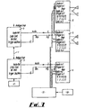
microphone 8 is connected directly to the amplifier to provide a facility for firemen to issue voice messages directly through the system when required. - Referring to figure 3, a block circuit diagram of a multiple zone system is shown. Parts equivalent to parts of the embodiments of figures 1 and 2 bear the same reference numerals. Any number of fire alarm
addressable modules 3 may be included in theFA loop 1. In this particular example two are shown. Also included in the loop is thecontrol equipment 2. Each module is constructed and operates as themodule 3 already described. In this way much larger systems to any desired size comprising essentially separate VA systems having individual modules could then be built up, the entire programming of these modules being part of the normal set up of the fire panel programming (providing the modules were chosen to emulate a class of analogue addressable output devices known as sounder controller modules). Fireman's evaluation control is carried out through a fireman'scontrol panel 10 connected to anamplifier 6 via a PA/VA switching/monitoring/routing matrix unit 11. Thisunit 11 is connected to all the amplifiers thereby interconnecting them in a manner required for a public address (PA) system. Provision may also be made for the connection of a fireman's microphone in a manner similar to that shown in the embodiment of figure 2. - Systems constructed in the above described manner are much cheaper than existing systems. They are easier to programme at the fire panel as standard module type programming may be used. Such programming would have been necessary in any event for sounders if conventional fire alarm sounders had been used. The need for a traditional interface between the voice alarm and fire alarm systems is removed as is the need to programme the voice alarm (VA) system itself. Complex systems may be built up in a modular fashion and a public address (PA) system may be added without having to change the existing switching matrix.
- The
module 3 may be programmable to react as a sounder control module. This automatically maps sounder ringing patterns from a fire alarm control panel to fire alarm sounders. Several significant advantages can be obtained as follows:- - The VA programming can simply be done at the FA panel by programming in the correct ringing patterns' a job easily done and known by the average FA engineer, without the need for any special programming tools and making the programming not dependant on any particular panel or function.
- The system(s) monitoring can be relayed back to the FA panel as a matter of course.
- Any triggers required to improve the sophistication/interfacing with e.g. a PA system can be embedded and transmitted out to the amplifier.
- In addition the
module 3 may include triggers and be able to monitor its trigger line to improve and obtain increased functionality and versatility and enable the expansion into much larger systems without the need for anything other than increased hardware to accommodate the number of speakers required. It should be noted that the module may be partially loop powered i.e. the bit that interfaces with the loop will be powered so as to report back fault signals. The audio output part will consume too much power and will therefore be powered through one of the connections to the amplifier. - It is intended that the 'module' 3 will interface with many different manufacturers amplifiers. The amplifier may be specifically designed to include functionality and features specifically designed to exploit the novelty of the unit.
- It will be appreciated that the above embodiment has been described by way of example only and that many variations are possible without departing from the scope of the invention.
Claims (14)
- An addressable fire alarm module comprising means for interfacing with an amplifier forming part of a voice alarm system, means for interfacing with a fire alarm loop along which data and power may be transmitted, a message store for storing one or more voice alarm messages and means for interpreting signals received from the loop and for selecting an appropriate message from the message store for transmission to the voice alarm system having regard to signals received from the loop.
- An addressable fire alarm module as claimed in claim 1, in which the loop comprises control equipment for controlling the transmission of power and data over the loop.
- An addressable fire alarm module as claimed in claim 1 or 2, in which means are provided for the connection of amplifiers.
- An addressable fire alarm module as claimed in claims 1, 2 or 3, in which a fireman's control panel is provided through which instructions can be fed to the system.
- An addressable fire alarm module as claimed in any preceding claim, in which an input/output interface is provided.
- An addressable fire alarm module as claimed in any preceding claim, in which a microcomputer and program store are provided.
- A addressable fire alarm module as claimed in any preceding claim, in which a fire alarm loop monitor and interface module are provided.
- An addressable fire alarm module as claimed in claim 7, in which the loop monitor and interface module are galvanically isolated from the remainder of the fire alarm module.
- An addressable fire alarm module as claimed in any preceding claim, in which a decoder is provided for decoding messages from the message store.
- An addressable fire alarm module as claimed in claim 7 or 8, in which the loop monitor and interface module comprise means enabling the monitor and module to be identified on the fire alarm loop.
- An addressable fire alarm module as claimed in any preceding claim, jn which a tone injector is provided.
- An addressable fire alarm module as claimed in any preceding claim, in which a digital to analogue converter is provided.
- An addressable fire alarm module as claimed in any preceding claim, in which a monitor and interface are provided operative to receive instructions from control and indicating equipment comprising the message store.
- A fire alarm system comprising a fire alarm loop along which data and power may be transmitted, a voice alarm system comprising one or more amplifiers, the or each amplifier being connected to one or more speakers for transmitting voice alarm messages, and one or more addressable fire alarm modules as claimed in any of claims 1 to
Applications Claiming Priority (3)
| Application Number | Priority Date | Filing Date | Title |
|---|---|---|---|
| GBGB0118442.3A GB0118442D0 (en) | 2001-07-28 | 2001-07-28 | A fire alarm module |
| GB0118442 | 2001-07-28 | ||
| PCT/GB2002/003447 WO2003012759A1 (en) | 2001-07-28 | 2002-07-26 | A fire alarm module |
Publications (2)
| Publication Number | Publication Date |
|---|---|
| EP1451787A1 EP1451787A1 (en) | 2004-09-01 |
| EP1451787B1 true EP1451787B1 (en) | 2005-09-21 |
Family
ID=9919375
Family Applications (1)
| Application Number | Title | Priority Date | Filing Date |
|---|---|---|---|
| EP02749071A Expired - Lifetime EP1451787B1 (en) | 2001-07-28 | 2002-07-26 | A fire alarm module |
Country Status (7)
| Country | Link |
|---|---|
| US (1) | US7142093B2 (en) |
| EP (1) | EP1451787B1 (en) |
| AT (1) | ATE305159T1 (en) |
| AU (1) | AU2002319484B2 (en) |
| DE (1) | DE60206296T2 (en) |
| GB (1) | GB0118442D0 (en) |
| WO (1) | WO2003012759A1 (en) |
Families Citing this family (8)
| Publication number | Priority date | Publication date | Assignee | Title |
|---|---|---|---|---|
| US7508303B2 (en) | 1999-11-10 | 2009-03-24 | Simplexgrinnell Lp | Alarm system with speaker |
| US7170396B2 (en) | 2004-06-21 | 2007-01-30 | Simplexgrinnell Lp | Addressable smart speaker |
| US7719407B2 (en) * | 2006-08-23 | 2010-05-18 | Honeywell International Inc. | Voice alarm system |
| EP2051220A1 (en) * | 2007-10-17 | 2009-04-22 | Siemens Building Technologies Fire & Security Products GmbH & Co. oHG | Separating device with energy storage for an electric circuit conducting energy |
| US7733222B2 (en) * | 2008-03-19 | 2010-06-08 | Honeywell International Inc. | Remotely controllable route indicating devices |
| JP7064890B2 (en) * | 2018-01-22 | 2022-05-11 | ホーチキ株式会社 | Fire alarm system |
| WO2020152730A1 (en) * | 2019-01-21 | 2020-07-30 | ホーチキ株式会社 | Fire alarm system and booster |
| GB2581349A (en) | 2019-02-12 | 2020-08-19 | Johnson Controls Fire Prot Lp | Voice alarm device |
Family Cites Families (9)
| Publication number | Priority date | Publication date | Assignee | Title |
|---|---|---|---|---|
| ATE25781T1 (en) * | 1982-07-16 | 1987-03-15 | Apollo Fire Detectors Ltd | SHORT-CIRCUIT FAULT INSULATION MEANS FOR CIRCUIT EQUIPMENT. |
| US4881058A (en) * | 1988-10-25 | 1989-11-14 | Audiosone, Inc. | Combined audible and visual alarm system |
| US5608375A (en) * | 1995-03-20 | 1997-03-04 | Wheelock Inc. | Synchronized visual/audible alarm system |
| US5724020A (en) * | 1996-05-16 | 1998-03-03 | Hsu; Ching-Fu | Voice warning system for fire accidents |
| GB2328769B (en) * | 1997-08-28 | 2001-05-16 | Menvier | Electrical apparatus |
| US6097289A (en) * | 1997-12-01 | 2000-08-01 | Forward Safety Systems Inc. | Intelligent speaker controller for a fire alarm system |
| US6060994A (en) * | 1999-01-20 | 2000-05-09 | Tempa Communication Inc. | Method for controlling united home security system |
| US6535121B2 (en) * | 1999-04-09 | 2003-03-18 | Richard K. Matheny | Fire department station zoned alerting control system |
| US6400265B1 (en) * | 2001-04-24 | 2002-06-04 | Microstrategy, Inc. | System and method for monitoring security systems by using video images |
-
2001
- 2001-07-28 GB GBGB0118442.3A patent/GB0118442D0/en not_active Ceased
-
2002
- 2002-07-26 WO PCT/GB2002/003447 patent/WO2003012759A1/en not_active Application Discontinuation
- 2002-07-26 AU AU2002319484A patent/AU2002319484B2/en not_active Expired
- 2002-07-26 DE DE60206296T patent/DE60206296T2/en not_active Expired - Lifetime
- 2002-07-26 US US10/485,066 patent/US7142093B2/en not_active Expired - Lifetime
- 2002-07-26 AT AT02749071T patent/ATE305159T1/en not_active IP Right Cessation
- 2002-07-26 EP EP02749071A patent/EP1451787B1/en not_active Expired - Lifetime
Also Published As
| Publication number | Publication date |
|---|---|
| US20040196145A1 (en) | 2004-10-07 |
| WO2003012759A1 (en) | 2003-02-13 |
| US7142093B2 (en) | 2006-11-28 |
| GB0118442D0 (en) | 2001-09-19 |
| AU2002319484B2 (en) | 2007-02-15 |
| DE60206296D1 (en) | 2006-02-02 |
| EP1451787A1 (en) | 2004-09-01 |
| DE60206296T2 (en) | 2006-06-22 |
| ATE305159T1 (en) | 2005-10-15 |
Similar Documents
| Publication | Publication Date | Title |
|---|---|---|
| US5887067A (en) | Audio communication system for a life safety network | |
| US7508303B2 (en) | Alarm system with speaker | |
| WO1995022129A1 (en) | User programmable paging system having priority-based, multiple input/output access capability | |
| WO2006009593A1 (en) | Addressable smart speaker | |
| EP1451787B1 (en) | A fire alarm module | |
| AU2002319484A1 (en) | A fire alarm module | |
| KR100417495B1 (en) | Broadcasting system using matrix type connection structure amp and speaker | |
| US20040165732A1 (en) | Speaker system and method for selectively activating speakers | |
| US8368528B2 (en) | Configurable notification device | |
| US8411875B2 (en) | Speaker control via audio connection | |
| JP3479135B2 (en) | Disaster prevention monitoring device | |
| US20050113947A1 (en) | Programmable system panel apparatus and method | |
| US20230129804A1 (en) | Fire alarm speaker circuits for dual-purpose spaces | |
| CN220564046U (en) | Elevator intercom device capable of reporting station by voice | |
| KR100888252B1 (en) | Control system for switching speaker individually | |
| JP2001043462A (en) | Flexibly correspondable disaster protecting receiver capable of selective setting for voltage impressed output and voltage nonimpressed output | |
| JP3612496B2 (en) | Wireless device and remote monitoring control method thereof | |
| KR101640752B1 (en) | An apparatus for distributing reverse amp sound source and the method thereof | |
| KR20230014961A (en) | A speaker line check and line audio conversion device, local broadcasting system and broadcast monitoring system | |
| JPH04354298A (en) | Home security system | |
| JPH06280500A (en) | Tunnel fire prevention system | |
| KR101099989B1 (en) | Emergency calling system using fsk | |
| JP2006302189A (en) | Fire alarm system with test functions | |
| JPH08249577A (en) | Fire alarm facilities | |
| JPS621099A (en) | Telecontroller |
Legal Events
| Date | Code | Title | Description |
|---|---|---|---|
| PUAI | Public reference made under article 153(3) epc to a published international application that has entered the european phase |
Free format text: ORIGINAL CODE: 0009012 |
|
| 17P | Request for examination filed |
Effective date: 20031201 |
|
| AK | Designated contracting states |
Kind code of ref document: A1 Designated state(s): AT BE BG CH CY CZ DE DK EE ES FI FR GB GR IE IT LI LU MC NL PT SE SK TR |
|
| AX | Request for extension of the european patent |
Extension state: AL LT LV MK RO SI |
|
| 17Q | First examination report despatched |
Effective date: 20040826 |
|
| GRAP | Despatch of communication of intention to grant a patent |
Free format text: ORIGINAL CODE: EPIDOSNIGR1 |
|
| GRAS | Grant fee paid |
Free format text: ORIGINAL CODE: EPIDOSNIGR3 |
|
| GRAA | (expected) grant |
Free format text: ORIGINAL CODE: 0009210 |
|
| AK | Designated contracting states |
Kind code of ref document: B1 Designated state(s): AT BE BG CH CY CZ DE DK EE ES FI FR GB GR IE IT LI LU MC NL PT SE SK TR |
|
| PG25 | Lapsed in a contracting state [announced via postgrant information from national office to epo] |
Ref country code: SK Free format text: LAPSE BECAUSE OF FAILURE TO SUBMIT A TRANSLATION OF THE DESCRIPTION OR TO PAY THE FEE WITHIN THE PRESCRIBED TIME-LIMIT Effective date: 20050921 Ref country code: LI Free format text: LAPSE BECAUSE OF FAILURE TO SUBMIT A TRANSLATION OF THE DESCRIPTION OR TO PAY THE FEE WITHIN THE PRESCRIBED TIME-LIMIT Effective date: 20050921 Ref country code: FI Free format text: LAPSE BECAUSE OF FAILURE TO SUBMIT A TRANSLATION OF THE DESCRIPTION OR TO PAY THE FEE WITHIN THE PRESCRIBED TIME-LIMIT Effective date: 20050921 Ref country code: CZ Free format text: LAPSE BECAUSE OF FAILURE TO SUBMIT A TRANSLATION OF THE DESCRIPTION OR TO PAY THE FEE WITHIN THE PRESCRIBED TIME-LIMIT Effective date: 20050921 Ref country code: CH Free format text: LAPSE BECAUSE OF FAILURE TO SUBMIT A TRANSLATION OF THE DESCRIPTION OR TO PAY THE FEE WITHIN THE PRESCRIBED TIME-LIMIT Effective date: 20050921 Ref country code: BE Free format text: LAPSE BECAUSE OF FAILURE TO SUBMIT A TRANSLATION OF THE DESCRIPTION OR TO PAY THE FEE WITHIN THE PRESCRIBED TIME-LIMIT Effective date: 20050921 Ref country code: AT Free format text: LAPSE BECAUSE OF FAILURE TO SUBMIT A TRANSLATION OF THE DESCRIPTION OR TO PAY THE FEE WITHIN THE PRESCRIBED TIME-LIMIT Effective date: 20050921 Ref country code: NL Free format text: LAPSE BECAUSE OF FAILURE TO SUBMIT A TRANSLATION OF THE DESCRIPTION OR TO PAY THE FEE WITHIN THE PRESCRIBED TIME-LIMIT Effective date: 20050921 Ref country code: IT Free format text: LAPSE BECAUSE OF FAILURE TO SUBMIT A TRANSLATION OF THE DESCRIPTION OR TO PAY THE FEE WITHIN THE PRESCRIBED TIME-LIMIT;WARNING: LAPSES OF ITALIAN PATENTS WITH EFFECTIVE DATE BEFORE 2007 MAY HAVE OCCURRED AT ANY TIME BEFORE 2007. THE CORRECT EFFECTIVE DATE MAY BE DIFFERENT FROM THE ONE RECORDED. Effective date: 20050921 |
|
| REG | Reference to a national code |
Ref country code: GB Ref legal event code: FG4D |
|
| REG | Reference to a national code |
Ref country code: CH Ref legal event code: EP |
|
| REG | Reference to a national code |
Ref country code: IE Ref legal event code: FG4D |
|
| REF | Corresponds to: |
Ref document number: 60206296 Country of ref document: DE Date of ref document: 20051027 Kind code of ref document: P |
|
| PG25 | Lapsed in a contracting state [announced via postgrant information from national office to epo] |
Ref country code: SE Free format text: LAPSE BECAUSE OF FAILURE TO SUBMIT A TRANSLATION OF THE DESCRIPTION OR TO PAY THE FEE WITHIN THE PRESCRIBED TIME-LIMIT Effective date: 20051221 Ref country code: GR Free format text: LAPSE BECAUSE OF FAILURE TO SUBMIT A TRANSLATION OF THE DESCRIPTION OR TO PAY THE FEE WITHIN THE PRESCRIBED TIME-LIMIT Effective date: 20051221 Ref country code: DK Free format text: LAPSE BECAUSE OF FAILURE TO SUBMIT A TRANSLATION OF THE DESCRIPTION OR TO PAY THE FEE WITHIN THE PRESCRIBED TIME-LIMIT Effective date: 20051221 Ref country code: BG Free format text: LAPSE BECAUSE OF FAILURE TO SUBMIT A TRANSLATION OF THE DESCRIPTION OR TO PAY THE FEE WITHIN THE PRESCRIBED TIME-LIMIT Effective date: 20051221 |
|
| PG25 | Lapsed in a contracting state [announced via postgrant information from national office to epo] |
Ref country code: ES Free format text: LAPSE BECAUSE OF FAILURE TO SUBMIT A TRANSLATION OF THE DESCRIPTION OR TO PAY THE FEE WITHIN THE PRESCRIBED TIME-LIMIT Effective date: 20060101 |
|
| REF | Corresponds to: |
Ref document number: 60206296 Country of ref document: DE Date of ref document: 20060202 Kind code of ref document: P |
|
| PG25 | Lapsed in a contracting state [announced via postgrant information from national office to epo] |
Ref country code: PT Free format text: LAPSE BECAUSE OF FAILURE TO SUBMIT A TRANSLATION OF THE DESCRIPTION OR TO PAY THE FEE WITHIN THE PRESCRIBED TIME-LIMIT Effective date: 20060221 |
|
| NLV1 | Nl: lapsed or annulled due to failure to fulfill the requirements of art. 29p and 29m of the patents act | ||
| REG | Reference to a national code |
Ref country code: CH Ref legal event code: PL |
|
| ET | Fr: translation filed | ||
| PG25 | Lapsed in a contracting state [announced via postgrant information from national office to epo] |
Ref country code: IE Free format text: LAPSE BECAUSE OF NON-PAYMENT OF DUE FEES Effective date: 20060726 |
|
| PLBE | No opposition filed within time limit |
Free format text: ORIGINAL CODE: 0009261 |
|
| STAA | Information on the status of an ep patent application or granted ep patent |
Free format text: STATUS: NO OPPOSITION FILED WITHIN TIME LIMIT |
|
| PG25 | Lapsed in a contracting state [announced via postgrant information from national office to epo] |
Ref country code: MC Free format text: LAPSE BECAUSE OF NON-PAYMENT OF DUE FEES Effective date: 20060731 |
|
| 26N | No opposition filed |
Effective date: 20060622 |
|
| REG | Reference to a national code |
Ref country code: IE Ref legal event code: MM4A |
|
| PG25 | Lapsed in a contracting state [announced via postgrant information from national office to epo] |
Ref country code: EE Free format text: LAPSE BECAUSE OF FAILURE TO SUBMIT A TRANSLATION OF THE DESCRIPTION OR TO PAY THE FEE WITHIN THE PRESCRIBED TIME-LIMIT Effective date: 20050921 |
|
| PG25 | Lapsed in a contracting state [announced via postgrant information from national office to epo] |
Ref country code: LU Free format text: LAPSE BECAUSE OF NON-PAYMENT OF DUE FEES Effective date: 20060726 Ref country code: TR Free format text: LAPSE BECAUSE OF FAILURE TO SUBMIT A TRANSLATION OF THE DESCRIPTION OR TO PAY THE FEE WITHIN THE PRESCRIBED TIME-LIMIT Effective date: 20050921 |
|
| PG25 | Lapsed in a contracting state [announced via postgrant information from national office to epo] |
Ref country code: CY Free format text: LAPSE BECAUSE OF FAILURE TO SUBMIT A TRANSLATION OF THE DESCRIPTION OR TO PAY THE FEE WITHIN THE PRESCRIBED TIME-LIMIT Effective date: 20050921 |
|
| REG | Reference to a national code |
Ref country code: FR Ref legal event code: PLFP Year of fee payment: 14 |
|
| REG | Reference to a national code |
Ref country code: FR Ref legal event code: PLFP Year of fee payment: 15 |
|
| REG | Reference to a national code |
Ref country code: FR Ref legal event code: PLFP Year of fee payment: 16 |
|
| REG | Reference to a national code |
Ref country code: FR Ref legal event code: PLFP Year of fee payment: 17 |
|
| PGFP | Annual fee paid to national office [announced via postgrant information from national office to epo] |
Ref country code: FR Payment date: 20210729 Year of fee payment: 20 |
|
| PGFP | Annual fee paid to national office [announced via postgrant information from national office to epo] |
Ref country code: DE Payment date: 20210804 Year of fee payment: 20 Ref country code: GB Payment date: 20210729 Year of fee payment: 20 |
|
| REG | Reference to a national code |
Ref country code: DE Ref legal event code: R071 Ref document number: 60206296 Country of ref document: DE |
|
| REG | Reference to a national code |
Ref country code: GB Ref legal event code: PE20 Expiry date: 20220725 |
|
| PG25 | Lapsed in a contracting state [announced via postgrant information from national office to epo] |
Ref country code: GB Free format text: LAPSE BECAUSE OF EXPIRATION OF PROTECTION Effective date: 20220725 |