EP1451529B1 - Methods and apparatuses for reconstructing angle information - Google Patents
Methods and apparatuses for reconstructing angle information Download PDFInfo
- Publication number
- EP1451529B1 EP1451529B1 EP02789871A EP02789871A EP1451529B1 EP 1451529 B1 EP1451529 B1 EP 1451529B1 EP 02789871 A EP02789871 A EP 02789871A EP 02789871 A EP02789871 A EP 02789871A EP 1451529 B1 EP1451529 B1 EP 1451529B1
- Authority
- EP
- European Patent Office
- Prior art keywords
- amplitude data
- target
- sensors
- azimuth
- elevation
- Prior art date
- Legal status (The legal status is an assumption and is not a legal conclusion. Google has not performed a legal analysis and makes no representation as to the accuracy of the status listed.)
- Expired - Lifetime
Links
Images

Classifications
-
- G—PHYSICS
- G01—MEASURING; TESTING
- G01S—RADIO DIRECTION-FINDING; RADIO NAVIGATION; DETERMINING DISTANCE OR VELOCITY BY USE OF RADIO WAVES; LOCATING OR PRESENCE-DETECTING BY USE OF THE REFLECTION OR RERADIATION OF RADIO WAVES; ANALOGOUS ARRANGEMENTS USING OTHER WAVES
- G01S3/00—Direction-finders for determining the direction from which infrasonic, sonic, ultrasonic, or electromagnetic waves, or particle emission, not having a directional significance, are being received
- G01S3/78—Direction-finders for determining the direction from which infrasonic, sonic, ultrasonic, or electromagnetic waves, or particle emission, not having a directional significance, are being received using electromagnetic waves other than radio waves
- G01S3/782—Systems for determining direction or deviation from predetermined direction
- G01S3/783—Systems for determining direction or deviation from predetermined direction using amplitude comparison of signals derived from static detectors or detector systems
- G01S3/784—Systems for determining direction or deviation from predetermined direction using amplitude comparison of signals derived from static detectors or detector systems using a mosaic of detectors
Definitions
- the present invention relates generally to the fields of position sensors and the analysis of positional data. More particularly, it concerns methods and apparatuses for efficiently reconstructing angle information by analyzing data from a set of independent sensors. Even more particularly, it concerns the reconstruction of angle information by comparing a data set from independent sensors with a calibration data set and minimizing an error function between those sets of data to reconstruct angle information.
- U.S. Patent No. 5,724,047 involves a precision direction finding system for making precision angle of arrival estimates for a signal received through two antenna elements separated in space.
- Phase interferometry is used to determine a precise angle of arrival, with multiple ambiguities due to the periodic nature of the phase difference related to geometric angle.
- the interferometric ambiguities are resolved using the time difference of arrival (TDOA) of the signal at the two antenna elements.
- TDOA time difference of arrival
- TDOA is measured using leading edge envelope detection for simple pulsed signals, and predetection correlation for phase and frequency modulated signals.
- U.S. Patent No. 6,104,345 involves a method for the direction of arrival (DOA) tracking of at least one source, along a single azimuth axis or along both azimuth and elevation axes.
- the method includes the steps of selecting all the high peaks from a DOA function as potential track points, converting the potential track points into a plurality of tracks and selecting a true track from the plurality of tracks.
- This methodology also suffers from some shortcomings; for example, it may be desirable to avoid the particular computational complexity involved with selecting a true track from the plurality of potential track points.
- U.S. Patent No. 4,562,439 involves an imaging radar seeker for producing two-dimensional images of a target, which can be mounted on a missile or other moving body, such as an automobile.
- a computer directs the seeker to operate sequentially in searching, tracking, and imaging modes.
- searching mode a combination of circumferential rotation of an antenna of the seeker and frequency scanning of electromagnetic energy fed to the antenna enables the seeker to search for its target over a conical field-of-view or a wider, peripheral belt field-of-view.
- In the imaging mode circumferential rotation of an antenna is stopped, and the tilt angle of a linear array of the antenna is stepped or continuously moved to compensate for radial movement of a radiated beam caused by frequency stepping imparted by a frequency synthesizer. This keeps the beam fixed in space and centered on the target.
- Inverse synthetic aperture imaging is used to create a two-dimensional image of the target wherein the first dimension (range) is obtained by performing inverse Fourier transforms on the echo signals, and the second orthogonal dimension (cross-range or doppler frequency) is obtained by performing Fourier transforms.
- the array can be a linear array of E-plane stacked linear waveguide antenna elements operating in either the traveling wave mode or the standing wave mode. Such methodology too exhibits shortcomings at least due to its complexity, lack of flexibility, and its inability to more efficiently perform angle reconstruction determinations.
- U.S. Patent No. 5,818,393 involves a fixed body wide field-of-view conformal antenna array suitable for broadband precision direction finding on missile platforms.
- the array is configured as multiple sub-arrays of spiral antennas that cover particular regions within the desired field-of-view of the entire array.
- a lower cost, more reliable and more accurate direction finding solution for missile needs is provided, primarily by the elimination of conventional radomes and antenna gimbal structures.
- the array can be configured to include multi-mode sensors. Although useful in this elimination of structures, this methodology exhibits room for significant improvement given its inability to more efficiently reconstruct angular information.
- U.S. Patent No. 6,313,794 uses feedback from RF carrier frequency measurements to disassociate the emitter angle-of-arrival component in the ambiguous phase measurement from the initially unknown phase measurement integer ambiguities. It then resolves the ambiguities and obtains the correct emitter angle-of-arrival (AOA). This is accomplished by converting the actual interferometer baselines on which the unassociated pulse phase measurements were made at different emitter frequencies to a baseline set for a single-frequency equivalent interferometer array.
- This methodology suffers from issues relating to complexity, flexibility, and the inability to more quickly and efficiently reconstruct high-resolution angular information.
- U.S. Patent No. 5,657,251 involves a computer-implemented process for processing incoming target data from a focal plane or scanning radar to accomplish multiple Target Tracking. Inputs are pixel plane coordinates and intensity of target blips.
- the Intelligent Target Tracking Processor employs an optimal target tracking algorithm. An optimal observation-to-track assignment exists when all target blips in a new frame of target data are matched up with nearby tracks, such that the sum of all the distances from each target blip to its assigned track is minimized.
- An expert system is used to control overall processing flow and provide efficient allocation of computing resources. Target blips without near neighbors are allowed to go directly to a real track table of established tracks, if their coordinates match-up with projected tracking gates.
- target blips are tested sequentially against two-frame, three-frame and four- or higher-frame discriminants, to reject blips not belonging to established tracks.
- the ITTP can partition the pixel plane into "bite size partitions", each with a manageable number of target blips, which is handles sequentially.
- the ITTP is designed to handle hundreds or thousands of targets as a stand-alone processor as is required in space object tracking or military scenarios.
- the expert system maintains an optimum balance between correlating on existing tracks and discriminating against impossible tracks. A total of 26 different metric and radiometric target tracking discriminants are employed.
- the ITTP is a dynamically and optimally configured set of general purpose parallel processors. Although useful for trajectory tracking for applications such as air-traffic controlling, this methodology nevertheless includes shortcomings; for instance, it does not allow for the reconstruction of high quality, high resolution angle information using a plurality of independent sensors or detectors on an image plane.
- US-A04,979,221 European Space Agency
- the invention provides a system in accordance with claim 8.
- the invention is a system for determining angular information from a target.
- the system includes a plurality of sensors and a computer.
- the computer is configured to: (a) acquire measured amplitude data from the plurality of sensors; (b) estimate an azimuth and elevation using the measured amplitude data; (c) access calibrated amplitude data corresponding to the azimuth and elevation; (d) determine a residual error between the measured amplitude data and the calibrated amplitude data; and (e) output the angular information as corresponding to the azimuth and elevation at which the residual error is minimized.
- the present disclosure describes apparatuses and methods for efficiently determining high-quality, high-resolution angle information from several independent sensors on an image plane.
- Applications for this technology are vast. For instance, one may use the techniques disclosed herein in a variety of military applications. Similarly, one may find applications in aircraft traffic controlling, general target seeking and/or tracking, and any other application where angular information is required. With the benefit of the present disclosure, those having skill in the art will comprehend that the techniques disclosed herein may be modified and applied to a number of additional, different applications. The present disclosure and claims attached hereto cover all such modifications that fall within the scope of this disclosure.
- the techniques for determining angle information may take the form of what the inventor has coined an "angle reconstruction algorithm.”
- the angle reconstruction algorithm is one method for improving the resolution and quality of angle information from relative amplitude measurement information given a set of independent sensors or detectors on an image plane. These sensors may be part of a CCD, thermal imaging array, a quadrant detector, or any other device suitable for gathering data relevant to angular information.
- the angle reconstruction process may involve producing a "match" between predicted or calibrated relative amplitude responses and measured relative amplitude responses. In one embodiment, this match may involve minimizing a residual error function, although those having skill in the art will understand that other mathematical techniques may be employed to determine a correspondence between the predicted or calibrated amplitudes and the measured responses.
- a LASER seeker field-of-view may be broken up into a plurality of distinct pixels.
- seven pixels may be used, although more or fewer pixels may be utilized depending upon preference and/or the specific application in question.
- a point source may be defocused on the image plane such that a plurality of sensors respond to a given target pulse.
- a point source may be defocused such that at least 3 of 7 independent detectors respond to a target pulse.
- the resulting amplitudes from each of the detectors (7 in the embodiment discussed above) for a given received pulse may then be compared with expected amplitudes from either predictions or calibration data for each location in the FOV.
- the location in the FOV that produces a match or correspondence which may take the form of exhibiting the least residual error between the predicted response magnitudes and the actual response amplitude measurements, is then determined to be the target's location in the field of view. Hence, angle (and position) information may be efficiently obtained.
- a rather robust and computationally-intensive approach is to accomplish a grid search of a region of interest.
- the residual between the amplitude response prediction and the actual measured amplitude response may be compared for all grid points.
- the grid point resulting in the lowest residual is assumed to be the best estimate of the targets location in the FOV.
- refinement of the grid search interval may be accomplished until a particular desired level of accuracy is achieved.
- Angle reconstruction techniques of this disclosure applied to an imaging array or other sensors provide for angle resolution much greater than would be derived based on the estimated angular extent of a pixel on the image plane. Intentional defocusing of the target (when angular extent is less than 1 pixel) or point target allows for relative amplitude data to be collected on multiple adjacent pixels. The relative amplitude data from each pixel can then be utilized to determine the power centroid of an extended target or a point source in the FOV.
- Apparatuses suitable for implementing aspects of the methods described herein may include equipment known in the art such as sensors, detectors, seekers, etc. Additionally, the apparatuses may include one or more computers to analyze the sensor data, in accordance with the techniques described herein via corresponding software. The one or more computers may be networked and may be in contact with one or more local or remote databases or storage networks that store calibration or prediction data sets relating to the sensors or arrays.
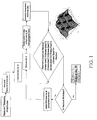
- FIG. 1 there is shown a flowchart illustrating one embodiment of a suitable angle reconstruction algorithm in which 7 detectors are used.
- amplitudes from the seven detectors are first measured (a) and then normalized, if necessary. This information is used to form an initial estimate (b) of both azimuth (AZ) and elevation (E1) information.
- AZ azimuth
- E1 elevation
- Using a database or another appropriate storage device or network one may then extract amplitude information corresponding to the initially-estimated AZ and E1 from calibration or prediction data. This amplitude information may be normalized, if necessary.
- a residual error function a residual error function (d) (or determine a Correspondence between the data sets using an alternative method).
- the amplitude residual is determined by considering the difference between the measured amplitude and the amplitude from the calibration set, for each and every detector (detectors A through G). Specifically, one may sun the squares of the differences of those amplitudes, as shown, to arrive at the residual value.
- a meas means the measured amplitude from detector A
- a est means the amplitude at the estimated AZ and E1 from the calibration set.
- the initial estimate of AZ and E1 is updated (e), as shown.
- amplitude information may again be extracted from the calibration data set - this time, the calibration information will correspond to newly-estimated AZ and E1. Again, normalization of the calibration amplitude information may be required.
- a residual error function may be obtained by considering the differences between the measured and calibration amplitudes. And, once again, if the residual is not minimized, the estimate of AZ and E1 may be updated, thereby repeating the process.
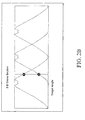
- FIGS. 2A and 2B show exemplary amplitude data from seven detectors.
- target location and angular information may be triangulated by comparison to a look up table (which may take the form of the calibration data set of prediction data discussed above).
- the look up table may be several dimensions, including 3.
- the look up table may be built-up via calibration steps. Specifically, one may position a target sequentially at various, known locations throughout a grid. At each location, one may take sensor readings from a plurality of sensors to obtain relative light amplitudes. Taking multiple readings of this sort builds up a library of amplitudes as a function of target locations. This library may then be used to compare with measured amplitudes in the fashion described herein (for example, by determining a residual error function) to quickly determine the angular and positional information of a target based on measured amplitude data from those same sensors.
Abstract
Description
- The present invention relates generally to the fields of position sensors and the analysis of positional data. More particularly, it concerns methods and apparatuses for efficiently reconstructing angle information by analyzing data from a set of independent sensors. Even more particularly, it concerns the reconstruction of angle information by comparing a data set from independent sensors with a calibration data set and minimizing an error function between those sets of data to reconstruct angle information.
- The ability to gather data from one or more sensors and translate that data into meaningful positional information is important in a wide variety of disciplines. For instance, tracking objects is essential for commercial aircraft controllers and an assortment of military applications.
- Over the years, sundry techniques aimed at determining positional information, such as angular information, from sensor readings have been developed. Although each has shown at least a degree of success in its respective application, room for significant improvement remains.
-
U.S. Patent No. 5,724,047 involves a precision direction finding system for making precision angle of arrival estimates for a signal received through two antenna elements separated in space. Phase interferometry is used to determine a precise angle of arrival, with multiple ambiguities due to the periodic nature of the phase difference related to geometric angle. The interferometric ambiguities are resolved using the time difference of arrival (TDOA) of the signal at the two antenna elements. TDOA is measured using leading edge envelope detection for simple pulsed signals, and predetection correlation for phase and frequency modulated signals. Although such phase interferometry determinations may exhibit certain advantages over other conventional methods, shortcomings remain due to, at least in part, the relatively complex nature of the computations required to implement the methodology. Further, reliance upon two antenna elements, rather than a plurality of independent sensors, may inhibit at least some flexibility of such a system. -
U.S. Patent No. 6,104,345 involves a method for the direction of arrival (DOA) tracking of at least one source, along a single azimuth axis or along both azimuth and elevation axes. The method includes the steps of selecting all the high peaks from a DOA function as potential track points, converting the potential track points into a plurality of tracks and selecting a true track from the plurality of tracks. This methodology also suffers from some shortcomings; for example, it may be desirable to avoid the particular computational complexity involved with selecting a true track from the plurality of potential track points. -
U.S. Patent No. 4,562,439 involves an imaging radar seeker for producing two-dimensional images of a target, which can be mounted on a missile or other moving body, such as an automobile. A computer directs the seeker to operate sequentially in searching, tracking, and imaging modes. In the searching mode, a combination of circumferential rotation of an antenna of the seeker and frequency scanning of electromagnetic energy fed to the antenna enables the seeker to search for its target over a conical field-of-view or a wider, peripheral belt field-of-view. In the imaging mode, circumferential rotation of an antenna is stopped, and the tilt angle of a linear array of the antenna is stepped or continuously moved to compensate for radial movement of a radiated beam caused by frequency stepping imparted by a frequency synthesizer. This keeps the beam fixed in space and centered on the target. Inverse synthetic aperture imaging is used to create a two-dimensional image of the target wherein the first dimension (range) is obtained by performing inverse Fourier transforms on the echo signals, and the second orthogonal dimension (cross-range or doppler frequency) is obtained by performing Fourier transforms. The array can be a linear array of E-plane stacked linear waveguide antenna elements operating in either the traveling wave mode or the standing wave mode. Such methodology too exhibits shortcomings at least due to its complexity, lack of flexibility, and its inability to more efficiently perform angle reconstruction determinations. -
U.S. Patent No. 5,818,393 involves a fixed body wide field-of-view conformal antenna array suitable for broadband precision direction finding on missile platforms. The array is configured as multiple sub-arrays of spiral antennas that cover particular regions within the desired field-of-view of the entire array. A lower cost, more reliable and more accurate direction finding solution for missile needs is provided, primarily by the elimination of conventional radomes and antenna gimbal structures. The array can be configured to include multi-mode sensors. Although useful in this elimination of structures, this methodology exhibits room for significant improvement given its inability to more efficiently reconstruct angular information. -
U.S. Patent No. 6,313,794 uses feedback from RF carrier frequency measurements to disassociate the emitter angle-of-arrival component in the ambiguous phase measurement from the initially unknown phase measurement integer ambiguities. It then resolves the ambiguities and obtains the correct emitter angle-of-arrival (AOA). This is accomplished by converting the actual interferometer baselines on which the unassociated pulse phase measurements were made at different emitter frequencies to a baseline set for a single-frequency equivalent interferometer array. This methodology, as with the methodologies described above, suffers from issues relating to complexity, flexibility, and the inability to more quickly and efficiently reconstruct high-resolution angular information. -
U.S. Patent No. 5,657,251 involves a computer-implemented process for processing incoming target data from a focal plane or scanning radar to accomplish multiple Target Tracking. Inputs are pixel plane coordinates and intensity of target blips. The Intelligent Target Tracking Processor (ITTP) employs an optimal target tracking algorithm. An optimal observation-to-track assignment exists when all target blips in a new frame of target data are matched up with nearby tracks, such that the sum of all the distances from each target blip to its assigned track is minimized. An expert system is used to control overall processing flow and provide efficient allocation of computing resources. Target blips without near neighbors are allowed to go directly to a real track table of established tracks, if their coordinates match-up with projected tracking gates. Otherwise, target blips are tested sequentially against two-frame, three-frame and four- or higher-frame discriminants, to reject blips not belonging to established tracks. The ITTP can partition the pixel plane into "bite size partitions", each with a manageable number of target blips, which is handles sequentially. The ITTP is designed to handle hundreds or thousands of targets as a stand-alone processor as is required in space object tracking or military scenarios. The expert system maintains an optimum balance between correlating on existing tracks and discriminating against impossible tracks. A total of 26 different metric and radiometric target tracking discriminants are employed. The ITTP is a dynamically and optimally configured set of general purpose parallel processors. Although useful for trajectory tracking for applications such as air-traffic controlling, this methodology nevertheless includes shortcomings; for instance, it does not allow for the reconstruction of high quality, high resolution angle information using a plurality of independent sensors or detectors on an image plane. -
US-A04,979,221 (European Space Agency) provides a method and apparatus for subpixel centroiding of a photon event. - Shortcomings listed above are reduced or eliminated by the techniques disclosed herein. These techniques are applicable to a vast number of applications, including general targeting and tracking applications.
- In accordance with one aspect of the invention there is provided is a method in accordance with
claim 1. - In another respect, the invention provides a system in accordance with claim 8.
- In another respect, the invention is a system for determining angular information from a target. The system includes a plurality of sensors and a computer. The computer is configured to: (a) acquire measured amplitude data from the plurality of sensors; (b) estimate an azimuth and elevation using the measured amplitude data; (c) access calibrated amplitude data corresponding to the azimuth and elevation; (d) determine a residual error between the measured amplitude data and the calibrated amplitude data; and (e) output the angular information as corresponding to the azimuth and elevation at which the residual error is minimized.
- Other features and associated advantages will become apparent with reference to the following detailed description of specific embodiments in connection with the accompanying drawings.
- The following drawings form part of the present specification and are included to further demonstrate certain aspects of the present invention. The invention may be better understood by reference to one or more of these drawings in combination with the detailed description of specific embodiments presented herein.
-
FIG. 1 is a flowchart showing techniques for reconstructing angle information in accordance with embodiments of the present disclosure. -
FIGS. 1A and2B show exemplary data involving angle information in accordance with embodiments of the present disclosure. - The present disclosure describes apparatuses and methods for efficiently determining high-quality, high-resolution angle information from several independent sensors on an image plane. Applications for this technology are vast. For instance, one may use the techniques disclosed herein in a variety of military applications. Similarly, one may find applications in aircraft traffic controlling, general target seeking and/or tracking, and any other application where angular information is required. With the benefit of the present disclosure, those having skill in the art will comprehend that the techniques disclosed herein may be modified and applied to a number of additional, different applications. The present disclosure and claims attached hereto cover all such modifications that fall within the scope of this disclosure.
- In one embodiment, the techniques for determining angle information may take the form of what the inventor has coined an "angle reconstruction algorithm." The angle reconstruction algorithm is one method for improving the resolution and quality of angle information from relative amplitude measurement information given a set of independent sensors or detectors on an image plane. These sensors may be part of a CCD, thermal imaging array, a quadrant detector, or any other device suitable for gathering data relevant to angular information. The angle reconstruction process may involve producing a "match" between predicted or calibrated relative amplitude responses and measured relative amplitude responses. In one embodiment, this match may involve minimizing a residual error function, although those having skill in the art will understand that other mathematical techniques may be employed to determine a correspondence between the predicted or calibrated amplitudes and the measured responses.
- In one embodiment, a LASER seeker field-of-view (FOV) may be broken up into a plurality of distinct pixels. In one embodiment, seven pixels may be used, although more or fewer pixels may be utilized depending upon preference and/or the specific application in question. A point source may be defocused on the image plane such that a plurality of sensors respond to a given target pulse. In the embodiment using seven pixels, for instance, a point source may be defocused such that at least 3 of 7 independent detectors respond to a target pulse.
- The resulting amplitudes from each of the detectors (7 in the embodiment discussed above) for a given received pulse may then be compared with expected amplitudes from either predictions or calibration data for each location in the FOV. The location in the FOV that produces a match or correspondence, which may take the form of exhibiting the least residual error between the predicted response magnitudes and the actual response amplitude measurements, is then determined to be the target's location in the field of view. Hence, angle (and position) information may be efficiently obtained.
- As will be understood by those having skill in the art, one may determine an appropriate correspondence between measured amplitudes and prediction or calibration sets of data in many ways, including the determination of a minimum residual error. In one embodiment, a rather robust and computationally-intensive approach is to accomplish a grid search of a region of interest. The residual between the amplitude response prediction and the actual measured amplitude response may be compared for all grid points. The grid point resulting in the lowest residual is assumed to be the best estimate of the targets location in the FOV. Refinement of the grid search interval may be accomplished until a particular desired level of accuracy is achieved.
- Other computationally-efficient methods of finding the location in the FOV with the lowest residual may be readily implemented according to programming and mathematical methods known in the art. Different methods may, of course, amount to a significant reduction in the computational effort required to find a target location in the field of view.
- Angle reconstruction techniques of this disclosure applied to an imaging array or other sensors provide for angle resolution much greater than would be derived based on the estimated angular extent of a pixel on the image plane. Intentional defocusing of the target (when angular extent is less than 1 pixel) or point target allows for relative amplitude data to be collected on multiple adjacent pixels. The relative amplitude data from each pixel can then be utilized to determine the power centroid of an extended target or a point source in the FOV.
- These techniques allow very noisy non-linear raw sensor data to be interpreted into angle of arrival (AOA) with the aid of a database and an appropriate calibration set of data or data forming the basis of a prediction set of data. Noise corruption of the measured signal levels often prevents a perfect match to angle of arrival to be made; however, extremely good estimates of angle of arrival may be readily made with an angle reconstruction algorithm as described herein. No loss of bandwidth need be realized since previous data does not have to be utilized in determining the angle of arrival output.
- Apparatuses suitable for implementing aspects of the methods described herein may include equipment known in the art such as sensors, detectors, seekers, etc. Additionally, the apparatuses may include one or more computers to analyze the sensor data, in accordance with the techniques described herein via corresponding software. The one or more computers may be networked and may be in contact with one or more local or remote databases or storage networks that store calibration or prediction data sets relating to the sensors or arrays.
- The following examples are included to demonstrate specific embodiments of this disclosure. It should be appreciated by those of skill in the art that the techniques disclosed in example which follow represent techniques discovered by the inventor to function well in the practice of the invention, and thus can be considered to constitute specific modes for its practice. However, those of skill in the art should, in light of the present disclosure, appreciate that many changes can be made in the specific embodiments which are disclosed and still obtain a like or similar result without departing from the scope of the invention.
- Turning to
FIG. 1 , there is shown a flowchart illustrating one embodiment of a suitable angle reconstruction algorithm in which 7 detectors are used. As the flowchart shows, amplitudes from the seven detectors are first measured (a) and then normalized, if necessary. This information is used to form an initial estimate (b) of both azimuth (AZ) and elevation (E1) information. Using a database or another appropriate storage device or network, one may then extract amplitude information corresponding to the initially-estimated AZ and E1 from calibration or prediction data. This amplitude information may be normalized, if necessary. With the measured and calibration amplitude information, both corresponding to the initially-estimated AZ and E1, one may then determine a residual error function (d) (or determine a Correspondence between the data sets using an alternative method). - In
FIG 1 , the amplitude residual is determined by considering the difference between the measured amplitude and the amplitude from the calibration set, for each and every detector (detectors A through G). Specifically, one may sun the squares of the differences of those amplitudes, as shown, to arrive at the residual value. InFIG 1 , Ameas means the measured amplitude from detector A, while Aest means the amplitude at the estimated AZ and E1 from the calibration set. - If this residual value is not the minimum value, the initial estimate of AZ and E1 is updated (e), as shown. With this new AZ and E1 estimate, amplitude information may again be extracted from the calibration data set - this time, the calibration information will correspond to newly-estimated AZ and E1. Again, normalization of the calibration amplitude information may be required. Once again, a residual error function may be obtained by considering the differences between the measured and calibration amplitudes. And, once again, if the residual is not minimized, the estimate of AZ and E1 may be updated, thereby repeating the process.
- However, if the residual is minimized, one may output the AZ and E1 that accountable for the minimization. It is this AZ and E1 that represents the angle informations of the target or object being studied (f).
-
FIGS. 2A and2B show exemplary amplitude data from seven detectors. - This example and the disclosure herein show that, in general, target location and angular information may be triangulated by comparison to a look up table (which may take the form of the calibration data set of prediction data discussed above). The look up table may be several dimensions, including 3. The look up table may be built-up via calibration steps. Specifically, one may position a target sequentially at various, known locations throughout a grid. At each location, one may take sensor readings from a plurality of sensors to obtain relative light amplitudes. Taking multiple readings of this sort builds up a library of amplitudes as a function of target locations. This library may then be used to compare with measured amplitudes in the fashion described herein (for example, by determining a residual error function) to quickly determine the angular and positional information of a target based on measured amplitude data from those same sensors.
- Shown in this example is course code, written in FORTRAN, that is suitable for carrying out steps described herein. This source code is exemplary only and does not limit the scope of the claims appended hereto. It simply represents once specific embodiment for carrying out aspects of this disclosure and is included for the convenience of the reader in this regard. Those having skill in the art, with the benefit of this disclosure, will recognize that a wide variety of computational techniques and different types of corresponding source code and software may be used in implementing the concepts described herein.


Claims (8)
- A method for determining angular information from a target, the method comprising the steps of:(a) obtaining measured amplitude data from a plurality of sensors;(b) estimating an azimuth and elevation using the measured amplitude data;(c) obtaining calibrated amplitude data corresponding to the azimuth and elevation;(d) determining a residual error between the measured amplitude data and the calibrated amplitude data;(e) characterized in that the method is capable of repeating steps (b) through (d) until the residual error is minimized; and(f) outputting the angular information as corresponding to the azimuth and elevation at which the residual error was minimized.
- The method of claim 1, wherein step (a) comprises obtaining measured amplitude data from seven sensors.
- The method of claim 1 or 2, wherein one or more of the sensors comprise a CCD, thermal imaging array, or a quadrant detector.
- The method of any one of the preceding claims, wherein step (a) comprises defocusing of the target.
- The method of any one of the preceding claims, further comprising the step of determining a power centroid of the target using the measured amplitude data.
- The method of any one of the preceding claims, wherein step d) comprises summing differences between the measured amplitude data and the calibrated amplitude data.
- The method of any one of the preceding claims, further comprising:(g) obtaining a plurality of sensors on an image plane; and(h) defocusing the target or a point target on the image plane such that one or more of the sensors respond to a target pulse.
- A system for determining angular information from a target, comprising:a plurality of sensors on an image plane; anda computer configured to:acquire measured amplitude data from the plurality of sensors;estimate an azimuth and elevation using the measured amplitude data;access calibrated amplitude data corresponding to the azimuth and elevation; andcharacterized in that the computer is also configured to determine a residual error between the measured amplitude data and the calibrated amplitude data; andoutput the angular information as corresponding to the azimuth and elevation at which the residual error is minimized.
Applications Claiming Priority (5)
| Application Number | Priority Date | Filing Date | Title |
|---|---|---|---|
| US301485 | 1999-04-28 | ||
| US33438601P | 2001-11-30 | 2001-11-30 | |
| US334386P | 2001-11-30 | ||
| US10/301,485 US6690458B2 (en) | 2001-11-30 | 2002-11-21 | Methods and apparatuses for reconstructing angle information |
| PCT/US2002/037784 WO2003048689A2 (en) | 2001-11-30 | 2002-11-25 | Methods and apparatuses for reconstructing angle information |
Publications (2)
| Publication Number | Publication Date |
|---|---|
| EP1451529A2 EP1451529A2 (en) | 2004-09-01 |
| EP1451529B1 true EP1451529B1 (en) | 2009-08-12 |
Family
ID=26972402
Family Applications (1)
| Application Number | Title | Priority Date | Filing Date |
|---|---|---|---|
| EP02789871A Expired - Lifetime EP1451529B1 (en) | 2001-11-30 | 2002-11-25 | Methods and apparatuses for reconstructing angle information |
Country Status (6)
| Country | Link |
|---|---|
| US (1) | US6690458B2 (en) |
| EP (1) | EP1451529B1 (en) |
| AT (1) | ATE439573T1 (en) |
| AU (1) | AU2002352911A1 (en) |
| DE (1) | DE60233345D1 (en) |
| WO (1) | WO2003048689A2 (en) |
Families Citing this family (9)
| Publication number | Priority date | Publication date | Assignee | Title |
|---|---|---|---|---|
| US7062077B1 (en) * | 1999-10-29 | 2006-06-13 | Helena Laboratories Corporation | Scanner densitometer and data evaluation method |
| US7190304B1 (en) | 2003-12-12 | 2007-03-13 | Bae Systems Information And Electronic Systems Integration Inc. | System for interception and defeat of rocket propelled grenades and method of use |
| DE102007045711A1 (en) * | 2007-09-24 | 2009-04-02 | Astrium Gmbh | Method and device for automatically determining the position of transceivers of navigation signals |
| US8487837B2 (en) * | 2008-11-06 | 2013-07-16 | Bae Systems Information And Electronic Systems Integration Inc. | Optical six-degree of freedom tracking apparatus and method |
| US8373105B2 (en) | 2009-02-19 | 2013-02-12 | Bae Systems Information And Electronic Systems Integration Inc. | Baffles and methods for distributed-aperture sensors |
| JP5439948B2 (en) * | 2009-05-20 | 2014-03-12 | 三菱電機株式会社 | Guiding device and target judging device |
| IL201110A (en) | 2009-09-22 | 2014-08-31 | Vorotec Ltd | Apparatus and method for navigation |
| DE102010055493A1 (en) * | 2010-12-15 | 2012-06-21 | Diehl Bgt Defence Gmbh & Co. Kg | Method for controlling a guided missile and seeker head for a guided missile |
| US10181643B2 (en) * | 2015-03-05 | 2019-01-15 | The Boeing Company | Approach to improve pointing accuracy of antenna systems with offset reflector and feed configuration |
Family Cites Families (12)
| Publication number | Priority date | Publication date | Assignee | Title |
|---|---|---|---|---|
| US4383663A (en) | 1976-06-01 | 1983-05-17 | The United States Of America As Represented By The Secretary Of The Navy | Active optical terminal homing |
| US4562439A (en) | 1982-12-13 | 1985-12-31 | Ford Aerospace & Communications Corporation | Imaging radar seeker |
| SE455539B (en) | 1986-05-23 | 1988-07-18 | Electrolux Ab | ELECTROOPTIC POSITION KNOWLEDGE SYSTEM FOR A PLAN REALLY FORMULA, PREFERRED A MOBILE ROBOT |
| FR2625396B1 (en) | 1987-12-23 | 1990-06-01 | Europ Agence Spatiale | METHOD AND DEVICE FOR DETERMINING THE POSITION OF THE CENTER OF A LIGHT SIGNAL RECEIVED IN A CHARGE-COUPLED MOSAIC DETECTOR |
| DE69221444T2 (en) | 1991-12-10 | 1998-02-12 | Texas Instruments Inc | Arrangement of several antennas for bearing with a large field of view adapted to a missile |
| US5273236A (en) | 1992-12-02 | 1993-12-28 | Electronics & Space Corp. | Multiple designation missile system |
| US5657251A (en) | 1995-10-02 | 1997-08-12 | Rockwell International Corporation | System and process for performing optimal target tracking |
| AU1983397A (en) * | 1996-02-29 | 1997-09-16 | Acuson Corporation | Multiple ultrasound image registration system, method and transducer |
| US5724047A (en) | 1996-11-27 | 1998-03-03 | Hughes Electronics | Phase and time-difference precision direction finding system |
| US6125308A (en) * | 1997-06-11 | 2000-09-26 | The United States Of America As Represented By The Secretary Of The Army | Method of passive determination of projectile miss distance |
| IL124053A (en) | 1998-04-09 | 2001-08-08 | Israel State | Tracking the direction of arrival of multiple targets |
| US6313794B1 (en) | 2000-01-19 | 2001-11-06 | Litton Systems, Inc. | Method of detection and determining an angular location of frequency agile emitters |
-
2002
- 2002-11-21 US US10/301,485 patent/US6690458B2/en not_active Expired - Lifetime
- 2002-11-25 AT AT02789871T patent/ATE439573T1/en not_active IP Right Cessation
- 2002-11-25 DE DE60233345T patent/DE60233345D1/en not_active Expired - Lifetime
- 2002-11-25 WO PCT/US2002/037784 patent/WO2003048689A2/en not_active Application Discontinuation
- 2002-11-25 EP EP02789871A patent/EP1451529B1/en not_active Expired - Lifetime
- 2002-11-25 AU AU2002352911A patent/AU2002352911A1/en not_active Abandoned
Also Published As
| Publication number | Publication date |
|---|---|
| AU2002352911A8 (en) | 2003-06-17 |
| US6690458B2 (en) | 2004-02-10 |
| WO2003048689A3 (en) | 2004-03-11 |
| ATE439573T1 (en) | 2009-08-15 |
| AU2002352911A1 (en) | 2003-06-17 |
| WO2003048689A2 (en) | 2003-06-12 |
| EP1451529A2 (en) | 2004-09-01 |
| DE60233345D1 (en) | 2009-09-24 |
| US20030142295A1 (en) | 2003-07-31 |
Similar Documents
| Publication | Publication Date | Title |
|---|---|---|
| US7916068B2 (en) | Generalized inner product method and apparatus for improved detection and discrimination | |
| US4723124A (en) | Extended SAR imaging capability for ship classification | |
| US5990834A (en) | Radar angle determination with music direction finding | |
| EP1485729B1 (en) | System and method for target signature calculation and recognition | |
| JP2002533685A (en) | SAR radar system | |
| WO1992008149A1 (en) | Radar apparatus | |
| CN110673086A (en) | Two-dimensional angle super-resolution method based on digital array radar | |
| CN109061638B (en) | Phased array close-range digital imaging method | |
| EP3775989B1 (en) | Device, system and method for localization of a target in a scene | |
| EP1451529B1 (en) | Methods and apparatuses for reconstructing angle information | |
| Yang et al. | An optimal polar format refocusing method for bistatic SAR moving target imaging | |
| Shastri et al. | mmSCALE: Self-calibration of mmWave radar networks from human movement trajectories | |
| Fu et al. | A low SNR and fast passive location algorithm based on virtual time reversal | |
| RU2150714C1 (en) | Method of measurement of cross-sectional dimensions of radar objects in real time | |
| CN115436896A (en) | Rapid radar single-snapshot MUSIC angle measurement method | |
| Chen et al. | A novel motion compensation scheme for 2-D multichannel SAR systems with quaternion posture calculation | |
| André et al. | Spatially variant incoherence trimming for improved SAR CCD | |
| CN114265058A (en) | MIMO radar target angle measurement method and device, electronic equipment and storage medium | |
| RU2672092C1 (en) | Method of measuring the angular position of terrestrial fixed radio-contrast objects | |
| Lipka et al. | Recursive phase extraction for holographic localization of incoherent FMCW beacons | |
| Omori et al. | K-space decomposition based super-resolution three-dimensional imaging method for millimeter wave radar | |
| RU2716145C1 (en) | Method for spatial localization of radio-emitting objects | |
| RU2716004C1 (en) | Method for spatial localization of radio transmitters | |
| CN112183205B (en) | Distributed radar high-precision angle measurement method and system | |
| CN113702971B (en) | Radar beam width design method for synthetic aperture passive positioning system |
Legal Events
| Date | Code | Title | Description |
|---|---|---|---|
| PUAI | Public reference made under article 153(3) epc to a published international application that has entered the european phase |
Free format text: ORIGINAL CODE: 0009012 |
|
| 17P | Request for examination filed |
Effective date: 20040622 |
|
| AK | Designated contracting states |
Kind code of ref document: A2 Designated state(s): AT BE BG CH CY CZ DE DK EE ES FI FR GB GR IE IT LI LU MC NL PT SE SK TR |
|
| AX | Request for extension of the european patent |
Extension state: AL LT LV MK RO SI |
|
| 17Q | First examination report despatched |
Effective date: 20080711 |
|
| GRAP | Despatch of communication of intention to grant a patent |
Free format text: ORIGINAL CODE: EPIDOSNIGR1 |
|
| GRAS | Grant fee paid |
Free format text: ORIGINAL CODE: EPIDOSNIGR3 |
|
| GRAA | (expected) grant |
Free format text: ORIGINAL CODE: 0009210 |
|
| AK | Designated contracting states |
Kind code of ref document: B1 Designated state(s): AT BE BG CH CY CZ DE DK EE ES FI FR GB GR IE IT LI LU MC NL PT SE SK TR |
|
| REG | Reference to a national code |
Ref country code: GB Ref legal event code: FG4D |
|
| REG | Reference to a national code |
Ref country code: CH Ref legal event code: EP |
|
| REG | Reference to a national code |
Ref country code: IE Ref legal event code: FG4D |
|
| REF | Corresponds to: |
Ref document number: 60233345 Country of ref document: DE Date of ref document: 20090924 Kind code of ref document: P |
|
| PG25 | Lapsed in a contracting state [announced via postgrant information from national office to epo] |
Ref country code: SE Free format text: LAPSE BECAUSE OF FAILURE TO SUBMIT A TRANSLATION OF THE DESCRIPTION OR TO PAY THE FEE WITHIN THE PRESCRIBED TIME-LIMIT Effective date: 20090812 Ref country code: ES Free format text: LAPSE BECAUSE OF FAILURE TO SUBMIT A TRANSLATION OF THE DESCRIPTION OR TO PAY THE FEE WITHIN THE PRESCRIBED TIME-LIMIT Effective date: 20091123 Ref country code: FI Free format text: LAPSE BECAUSE OF FAILURE TO SUBMIT A TRANSLATION OF THE DESCRIPTION OR TO PAY THE FEE WITHIN THE PRESCRIBED TIME-LIMIT Effective date: 20090812 Ref country code: AT Free format text: LAPSE BECAUSE OF FAILURE TO SUBMIT A TRANSLATION OF THE DESCRIPTION OR TO PAY THE FEE WITHIN THE PRESCRIBED TIME-LIMIT Effective date: 20090812 |
|
| NLV1 | Nl: lapsed or annulled due to failure to fulfill the requirements of art. 29p and 29m of the patents act | ||
| PG25 | Lapsed in a contracting state [announced via postgrant information from national office to epo] |
Ref country code: NL Free format text: LAPSE BECAUSE OF FAILURE TO SUBMIT A TRANSLATION OF THE DESCRIPTION OR TO PAY THE FEE WITHIN THE PRESCRIBED TIME-LIMIT Effective date: 20090812 |
|
| PG25 | Lapsed in a contracting state [announced via postgrant information from national office to epo] |
Ref country code: PT Free format text: LAPSE BECAUSE OF FAILURE TO SUBMIT A TRANSLATION OF THE DESCRIPTION OR TO PAY THE FEE WITHIN THE PRESCRIBED TIME-LIMIT Effective date: 20091212 Ref country code: BG Free format text: LAPSE BECAUSE OF FAILURE TO SUBMIT A TRANSLATION OF THE DESCRIPTION OR TO PAY THE FEE WITHIN THE PRESCRIBED TIME-LIMIT Effective date: 20091112 |
|
| PG25 | Lapsed in a contracting state [announced via postgrant information from national office to epo] |
Ref country code: EE Free format text: LAPSE BECAUSE OF FAILURE TO SUBMIT A TRANSLATION OF THE DESCRIPTION OR TO PAY THE FEE WITHIN THE PRESCRIBED TIME-LIMIT Effective date: 20090812 Ref country code: CZ Free format text: LAPSE BECAUSE OF FAILURE TO SUBMIT A TRANSLATION OF THE DESCRIPTION OR TO PAY THE FEE WITHIN THE PRESCRIBED TIME-LIMIT Effective date: 20090812 Ref country code: DK Free format text: LAPSE BECAUSE OF FAILURE TO SUBMIT A TRANSLATION OF THE DESCRIPTION OR TO PAY THE FEE WITHIN THE PRESCRIBED TIME-LIMIT Effective date: 20090812 |
|
| PG25 | Lapsed in a contracting state [announced via postgrant information from national office to epo] |
Ref country code: SK Free format text: LAPSE BECAUSE OF FAILURE TO SUBMIT A TRANSLATION OF THE DESCRIPTION OR TO PAY THE FEE WITHIN THE PRESCRIBED TIME-LIMIT Effective date: 20090812 |
|
| PLBE | No opposition filed within time limit |
Free format text: ORIGINAL CODE: 0009261 |
|
| STAA | Information on the status of an ep patent application or granted ep patent |
Free format text: STATUS: NO OPPOSITION FILED WITHIN TIME LIMIT |
|
| PG25 | Lapsed in a contracting state [announced via postgrant information from national office to epo] |
Ref country code: MC Free format text: LAPSE BECAUSE OF NON-PAYMENT OF DUE FEES Effective date: 20091130 Ref country code: BE Free format text: LAPSE BECAUSE OF FAILURE TO SUBMIT A TRANSLATION OF THE DESCRIPTION OR TO PAY THE FEE WITHIN THE PRESCRIBED TIME-LIMIT Effective date: 20090812 |
|
| REG | Reference to a national code |
Ref country code: CH Ref legal event code: PL |
|
| 26N | No opposition filed |
Effective date: 20100517 |
|
| PG25 | Lapsed in a contracting state [announced via postgrant information from national office to epo] |
Ref country code: LI Free format text: LAPSE BECAUSE OF NON-PAYMENT OF DUE FEES Effective date: 20091130 Ref country code: IE Free format text: LAPSE BECAUSE OF NON-PAYMENT OF DUE FEES Effective date: 20091125 Ref country code: GR Free format text: LAPSE BECAUSE OF FAILURE TO SUBMIT A TRANSLATION OF THE DESCRIPTION OR TO PAY THE FEE WITHIN THE PRESCRIBED TIME-LIMIT Effective date: 20091113 Ref country code: CH Free format text: LAPSE BECAUSE OF NON-PAYMENT OF DUE FEES Effective date: 20091130 |
|
| PG25 | Lapsed in a contracting state [announced via postgrant information from national office to epo] |
Ref country code: IT Free format text: LAPSE BECAUSE OF FAILURE TO SUBMIT A TRANSLATION OF THE DESCRIPTION OR TO PAY THE FEE WITHIN THE PRESCRIBED TIME-LIMIT Effective date: 20090812 |
|
| PG25 | Lapsed in a contracting state [announced via postgrant information from national office to epo] |
Ref country code: LU Free format text: LAPSE BECAUSE OF NON-PAYMENT OF DUE FEES Effective date: 20091125 |
|
| PG25 | Lapsed in a contracting state [announced via postgrant information from national office to epo] |
Ref country code: TR Free format text: LAPSE BECAUSE OF FAILURE TO SUBMIT A TRANSLATION OF THE DESCRIPTION OR TO PAY THE FEE WITHIN THE PRESCRIBED TIME-LIMIT Effective date: 20090812 |
|
| PG25 | Lapsed in a contracting state [announced via postgrant information from national office to epo] |
Ref country code: CY Free format text: LAPSE BECAUSE OF FAILURE TO SUBMIT A TRANSLATION OF THE DESCRIPTION OR TO PAY THE FEE WITHIN THE PRESCRIBED TIME-LIMIT Effective date: 20090812 |
|
| REG | Reference to a national code |
Ref country code: FR Ref legal event code: PLFP Year of fee payment: 14 |
|
| REG | Reference to a national code |
Ref country code: FR Ref legal event code: PLFP Year of fee payment: 15 |
|
| REG | Reference to a national code |
Ref country code: FR Ref legal event code: PLFP Year of fee payment: 16 |
|
| PGFP | Annual fee paid to national office [announced via postgrant information from national office to epo] |
Ref country code: DE Payment date: 20211126 Year of fee payment: 20 Ref country code: FR Payment date: 20211124 Year of fee payment: 20 Ref country code: GB Payment date: 20211129 Year of fee payment: 20 |
|
| REG | Reference to a national code |
Ref country code: DE Ref legal event code: R071 Ref document number: 60233345 Country of ref document: DE |
|
| REG | Reference to a national code |
Ref country code: GB Ref legal event code: PE20 Expiry date: 20221124 |
|
| PG25 | Lapsed in a contracting state [announced via postgrant information from national office to epo] |
Ref country code: GB Free format text: LAPSE BECAUSE OF EXPIRATION OF PROTECTION Effective date: 20221124 |