EP1451496B1 - Control valve pressure bleed inspection port - Google Patents
Control valve pressure bleed inspection port Download PDFInfo
- Publication number
- EP1451496B1 EP1451496B1 EP02803619A EP02803619A EP1451496B1 EP 1451496 B1 EP1451496 B1 EP 1451496B1 EP 02803619 A EP02803619 A EP 02803619A EP 02803619 A EP02803619 A EP 02803619A EP 1451496 B1 EP1451496 B1 EP 1451496B1
- Authority
- EP
- European Patent Office
- Prior art keywords
- valve body
- bonnet
- valve
- bore
- passageway
- Prior art date
- Legal status (The legal status is an assumption and is not a legal conclusion. Google has not performed a legal analysis and makes no representation as to the accuracy of the status listed.)
- Expired - Lifetime
Links
Images

Classifications
-
- F—MECHANICAL ENGINEERING; LIGHTING; HEATING; WEAPONS; BLASTING
- F16—ENGINEERING ELEMENTS AND UNITS; GENERAL MEASURES FOR PRODUCING AND MAINTAINING EFFECTIVE FUNCTIONING OF MACHINES OR INSTALLATIONS; THERMAL INSULATION IN GENERAL
- F16K—VALVES; TAPS; COCKS; ACTUATING-FLOATS; DEVICES FOR VENTING OR AERATING
- F16K24/00—Devices, e.g. valves, for venting or aerating enclosures
- F16K24/02—Devices, e.g. valves, for venting or aerating enclosures the enclosure being itself a valve, tap, or cock
-
- F—MECHANICAL ENGINEERING; LIGHTING; HEATING; WEAPONS; BLASTING
- F16—ENGINEERING ELEMENTS AND UNITS; GENERAL MEASURES FOR PRODUCING AND MAINTAINING EFFECTIVE FUNCTIONING OF MACHINES OR INSTALLATIONS; THERMAL INSULATION IN GENERAL
- F16K—VALVES; TAPS; COCKS; ACTUATING-FLOATS; DEVICES FOR VENTING OR AERATING
- F16K27/00—Construction of housing; Use of materials therefor
- F16K27/02—Construction of housing; Use of materials therefor of lift valves
-
- Y—GENERAL TAGGING OF NEW TECHNOLOGICAL DEVELOPMENTS; GENERAL TAGGING OF CROSS-SECTIONAL TECHNOLOGIES SPANNING OVER SEVERAL SECTIONS OF THE IPC; TECHNICAL SUBJECTS COVERED BY FORMER USPC CROSS-REFERENCE ART COLLECTIONS [XRACs] AND DIGESTS
- Y10—TECHNICAL SUBJECTS COVERED BY FORMER USPC
- Y10S—TECHNICAL SUBJECTS COVERED BY FORMER USPC CROSS-REFERENCE ART COLLECTIONS [XRACs] AND DIGESTS
- Y10S285/00—Pipe joints or couplings
- Y10S285/924—Vented
-
- Y—GENERAL TAGGING OF NEW TECHNOLOGICAL DEVELOPMENTS; GENERAL TAGGING OF CROSS-SECTIONAL TECHNOLOGIES SPANNING OVER SEVERAL SECTIONS OF THE IPC; TECHNICAL SUBJECTS COVERED BY FORMER USPC CROSS-REFERENCE ART COLLECTIONS [XRACs] AND DIGESTS
- Y10—TECHNICAL SUBJECTS COVERED BY FORMER USPC
- Y10T—TECHNICAL SUBJECTS COVERED BY FORMER US CLASSIFICATION
- Y10T137/00—Fluid handling
- Y10T137/5762—With leakage or drip collecting
-
- Y—GENERAL TAGGING OF NEW TECHNOLOGICAL DEVELOPMENTS; GENERAL TAGGING OF CROSS-SECTIONAL TECHNOLOGIES SPANNING OVER SEVERAL SECTIONS OF THE IPC; TECHNICAL SUBJECTS COVERED BY FORMER USPC CROSS-REFERENCE ART COLLECTIONS [XRACs] AND DIGESTS
- Y10—TECHNICAL SUBJECTS COVERED BY FORMER USPC
- Y10T—TECHNICAL SUBJECTS COVERED BY FORMER US CLASSIFICATION
- Y10T137/00—Fluid handling
- Y10T137/598—With repair, tapping, assembly, or disassembly means
-
- Y—GENERAL TAGGING OF NEW TECHNOLOGICAL DEVELOPMENTS; GENERAL TAGGING OF CROSS-SECTIONAL TECHNOLOGIES SPANNING OVER SEVERAL SECTIONS OF THE IPC; TECHNICAL SUBJECTS COVERED BY FORMER USPC CROSS-REFERENCE ART COLLECTIONS [XRACs] AND DIGESTS
- Y10—TECHNICAL SUBJECTS COVERED BY FORMER USPC
- Y10T—TECHNICAL SUBJECTS COVERED BY FORMER US CLASSIFICATION
- Y10T137/00—Fluid handling
- Y10T137/598—With repair, tapping, assembly, or disassembly means
- Y10T137/6065—Assembling or disassembling reciprocating valve
-
- Y—GENERAL TAGGING OF NEW TECHNOLOGICAL DEVELOPMENTS; GENERAL TAGGING OF CROSS-SECTIONAL TECHNOLOGIES SPANNING OVER SEVERAL SECTIONS OF THE IPC; TECHNICAL SUBJECTS COVERED BY FORMER USPC CROSS-REFERENCE ART COLLECTIONS [XRACs] AND DIGESTS
- Y10—TECHNICAL SUBJECTS COVERED BY FORMER USPC
- Y10T—TECHNICAL SUBJECTS COVERED BY FORMER US CLASSIFICATION
- Y10T137/00—Fluid handling
- Y10T137/8593—Systems
- Y10T137/87096—Valves with separate, correlated, actuators
- Y10T137/87121—Coaxial stems
Definitions
- This invention relates generally to control valves and, more specifically, to a control valve capable of indicating loss of integrity of a sealed threaded joint therein and to release internal pressure build-up within the control valve prior to disassembly of the control valve.
- control valves have heretofore suffered from an inability (or poor ability) to indicate when there has been a loss of integrity of seals within the control valve.
- an inability or poor ability
- the resulting pressure loss in the system could lead to costly, and even dangerous consequences, particularly when highly flammable fluids are being passed through the control valve.
- Another shortcoming of existing control valves has been the inability to detect the presence of internal pressure within the valve during disassembly.
- GB 1381927 discloses a valve according to the preamble of claim 1.
- a control valve In order to provide early detection of leakage in the seals within a control valve or in a bonnet of the control valve, a control valve according to claim 1 is provided.
- the valve assembly comprising: a valve body having an interior wall and an exterior wall; a bonnet threadedly engageable with said valve body; an interior cavity defined by the interior wall, said interior cavity having an inlet passageway and an outlet passageway; and a gasket disposed along the interior wall.
- the gasket provides a seal at an intersection of said bonnet and the interior wall of the valve body, and is disposed along the interior wall prior to the portion that threadedly receives the bonnet. It is directly exposed to an operating pressure of the valve and a fluid passing therethrough when the bonnet is completely threadedly received in the valve body.
- a bore extending through the valve body from the interior cavity to the exterior wall is provided.
- the bore is positioned in the region of the valve body which threadably engages with the bonnet, such that when the bonnet is completely threadedly received in the valve body an innermost opening of the bore is sealed from the interior cavity by the bonnet and the gasket.
- the bore permits at least one of equalization of the internal pressure with atmospheric pressure prior to the bonnet being completely removed from threaded engagement with the valve body and the passing of fluid therethrough from the interior cavity past the gasket in the event of a failure of the seal between the bonnet and the valve body.
- the control valve 10 includes a valve body 12 and a bonnet 14.
- the bonnet 14 is threadedly engaged with the valve body 12 by a plurality of female threads 16 in the valve body 12, and a plurality of male threads 18 (as best shown in FIG. 3) on the bonnet 14.
- a pressure bleed indicator is provided by means of a bore 20 through the valve body 12.
- the valve body 12 includes an exterior wall 21, an interior wall 23, an inlet 22 and an outlet 24.
- the interior wall 23 of the valve body 12 defines an interior cavity 25, including an inlet passageway 26 and an outlet passageway 28.
- the fluid inlet passageway 26 and the fluid outlet passageway 28 may be reversed, such that the fluid inlet passageway becomes the fluid outlet passageway, and the fluid outlet passageway becomes the fluid inlet passageway, thereby changing a downward flow valve to an upward flow valve.
- the fluid inlet and fluid outlet passageways may be at the same height as one another.
- An elastomeric gasket 32 helps maintain a seal between the bonnet 14 and the valve body 12 when the control valve 10 is fully assembled.
- the bonnet 14 When fully assembled, the bonnet 14 is preferably completely threadedly received in the valve body 12 such that the gasket 32 is in sealed contact with both the bonnet 14 and the valve body 12.
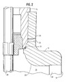
- the bore 20 of the pressure bleed indicator is preferably positioned such that when the gasket 32 is in sealed contact with both the bonnet 14 and the valve body 12, as shown in FIGS. 1 and 2, the bonnet 14 sealingly covers an innermost opening 30 of the bore 20.
- control valves 10 of the type disclosed herein are frequently used, by way of example only, as dump valves for carrying away highly visible fluids containing hydrocarbons, and other waste fluids, during oil purification, as well as for many other applications involving flow control of fluids, both related and unrelated to oil purification, any fluids leaking out the pressure bleed indicator would advantageously be detectable, and if in liquid form, readily visible to passersby from outside the valve body 12.
- the present invention advantageously provides means by which any built-up internal pressure is equalized with atmospheric pressure before the bonnet 14 is completely disengaged from the valve body 12. Also, while removing the bonnet 14 while there is internal pressure in the control valve higher than atmospheric pressure, the bore 20 provides an audible and visual indicator of elevated internal pressure within the control valve 10. If such elevated internal pressure is detected, a technician has an opportunity to retighten the bonnet 14 and properly bleed pressure from the control valve 10.
- the bonnet and any fluid in the interior cavity of the valve may undesirably fly or eject from the valve body in an uncontrolled manner during disassembly.
- the control valve 10 described herein substantially reduces the likelihood of this potentially dangerous situation.
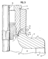
- FIG. 3 shows the internal pressure being released through the bore 20.
- a valve stem 36 having a valve plug 38 at a lower end thereof (see FIG. 1), moves upward. This upward movement of the valve stem 36 brings the valve plug 38 up off a valve seat 40.
- internal pressure of the control valve 10 is released upon exposure of the first open end 30 of the bore 20, regardless of whether the internal pressure had built up in the inlet passageway 28 or the outlet passageway 26.
- a second end 34 of the bore 20, located at the exterior wall 21 of the valve body 12, may be provided with an indicating means, such as a cover (not shown).
- an indicating means such as a cover (not shown).
- Such an indicating means could be actuated, upon release of internal pressure through the bore 20, from a closed position substantially covering the second end 34 to an open position, which would be a change visible to a technician or other maintenance person.
- This indicating means would show a person disassembling the bonnet from the control valve that the internal pressure had not previously been bled from the control valve prior to disassembly.
- control valve pressure bleed port has been described with respect to certain embodiments thereof, it will be understood by persons of ordinary skill in the art that the appended claims are not intended to be limited thereto, and that modifications can be made that are considered within the scope of the claims.
Landscapes
- Engineering & Computer Science (AREA)
- General Engineering & Computer Science (AREA)
- Mechanical Engineering (AREA)
- Indication Of The Valve Opening Or Closing Status (AREA)
- Examining Or Testing Airtightness (AREA)
- Safety Valves (AREA)
- Check Valves (AREA)
- Valve Housings (AREA)
- Compressor (AREA)
- Measuring Fluid Pressure (AREA)
Description
- This invention relates generally to control valves and, more specifically, to a control valve capable of indicating loss of integrity of a sealed threaded joint therein and to release internal pressure build-up within the control valve prior to disassembly of the control valve.
- Notwithstanding the myriad of valves available for controlling the flow of fluid into or through a system, control valves have heretofore suffered from an inability (or poor ability) to indicate when there has been a loss of integrity of seals within the control valve. When a seal within a control valve fails, unless detected early, the resulting pressure loss in the system could lead to costly, and even dangerous consequences, particularly when highly flammable fluids are being passed through the control valve. Another shortcoming of existing control valves has been the inability to detect the presence of internal pressure within the valve during disassembly. If the internal pressure of the control valve is not released in a safe, controlled manner, the bonnet of the control valve could prematurely dislodge from the control valve, or an uncontrolled amount of fluid within or passing through the control valve could suddenly be released. This is why there are protocols for isolating and bleeding pressure out of control valves prior to disassembly. Nevertheless, it would be desirable for a control valve to provide an integral way to bleed its internal pressure prior to disassembly.
- GB 1381927 discloses a valve according to the preamble of claim 1.
- The manner in which these and other shortcomings of existing control valves are overcome is described in the following Summary of the Invention, Detailed Description of an Exemplary Embodiment, and the Drawings.
- In order to provide early detection of leakage in the seals within a control valve or in a bonnet of the control valve, a control valve according to claim 1 is provided. The valve assembly comprising: a valve body having an interior wall and an exterior wall; a bonnet threadedly engageable with said valve body; an interior cavity defined by the interior wall, said interior cavity having an inlet passageway and an outlet passageway; and a gasket disposed along the interior wall. The gasket provides a seal at an intersection of said bonnet and the interior wall of the valve body, and is disposed along the interior wall prior to the portion that threadedly receives the bonnet. It is directly exposed to an operating pressure of the valve and a fluid passing therethrough when the bonnet is completely threadedly received in the valve body.
- A bore extending through the valve body from the interior cavity to the exterior wall is provided. The bore is positioned in the region of the valve body which threadably engages with the bonnet, such that when the bonnet is completely threadedly received in the valve body an innermost opening of the bore is sealed from the interior cavity by the bonnet and the gasket. The bore permits at least one of equalization of the internal pressure with atmospheric pressure prior to the bonnet being completely removed from threaded engagement with the valve body and the passing of fluid therethrough from the interior cavity past the gasket in the event of a failure of the seal between the bonnet and the valve body.
-
- FIG. 1 is a cross-sectional view of a control valve, showing a cross-section of the valve body having a pressure bleed indicator therein, and a bonnet threadedly engaged with the valve body;
- FIG. 2 is an enlarged cross-sectional view of the control valve shown in FIG. 1, showing the control valve body and bonnet in a sealed condition, with the bonnet in complete threaded engagement with the valve body; and
- FIG. 3 is an enlarged cross-sectional view of the control valve shown in FIG. 1, similar to FIG. 2, but showing the control valve just as the bonnet has started to be unthreaded from the complementary threads of the valve body, such that the interior cavity of the control valve is exposed to the pressure bleed port in the valve body.
- Referring to FIG. 1, the
control valve 10 includes avalve body 12 and abonnet 14. Thebonnet 14 is threadedly engaged with thevalve body 12 by a plurality offemale threads 16 in thevalve body 12, and a plurality of male threads 18 (as best shown in FIG. 3) on thebonnet 14. A pressure bleed indicator is provided by means of abore 20 through thevalve body 12. - The
valve body 12 includes anexterior wall 21, aninterior wall 23, aninlet 22 and anoutlet 24. Theinterior wall 23 of thevalve body 12 defines aninterior cavity 25, including aninlet passageway 26 and anoutlet passageway 28. In an alternate example, thefluid inlet passageway 26 and thefluid outlet passageway 28 may be reversed, such that the fluid inlet passageway becomes the fluid outlet passageway, and the fluid outlet passageway becomes the fluid inlet passageway, thereby changing a downward flow valve to an upward flow valve. As a further alternate example (not shown), the fluid inlet and fluid outlet passageways may be at the same height as one another. - An
elastomeric gasket 32, such as an o-ring, helps maintain a seal between thebonnet 14 and thevalve body 12 when thecontrol valve 10 is fully assembled. When fully assembled, thebonnet 14 is preferably completely threadedly received in thevalve body 12 such that thegasket 32 is in sealed contact with both thebonnet 14 and thevalve body 12. Thebore 20 of the pressure bleed indicator is preferably positioned such that when thegasket 32 is in sealed contact with both thebonnet 14 and thevalve body 12, as shown in FIGS. 1 and 2, thebonnet 14 sealingly covers aninnermost opening 30 of thebore 20. - As fluids, such as oil, water mixed with debris, or gas (although it will be understood by those of ordinary skill that these fluids are merely a few examples, and that the
control valve 10 can be used for a wide variety of fluids, too numerous to list herein), pass through theoutlet passageway 26 of thecontrol valve 10, the seal between thebonnet 14 and theinnermost opening 30 of thebore 20 prevents such fluids from leaking through thebore 20 of the pressure bleed indicator. If, however, there were to be a failure in thegasket 32, or elsewhere in the seal between thebonnet 14 and thevalve body 12, fluids in theoutlet passageway 28 would leak out thebore 20. - As
control valves 10 of the type disclosed herein are frequently used, by way of example only, as dump valves for carrying away highly visible fluids containing hydrocarbons, and other waste fluids, during oil purification, as well as for many other applications involving flow control of fluids, both related and unrelated to oil purification, any fluids leaking out the pressure bleed indicator would advantageously be detectable, and if in liquid form, readily visible to passersby from outside thevalve body 12. - In the event the
control valve 10 were not properly isolated and bled of its internal pressure prior to disassembly, the present invention advantageously provides means by which any built-up internal pressure is equalized with atmospheric pressure before thebonnet 14 is completely disengaged from thevalve body 12. Also, while removing thebonnet 14 while there is internal pressure in the control valve higher than atmospheric pressure, thebore 20 provides an audible and visual indicator of elevated internal pressure within thecontrol valve 10. If such elevated internal pressure is detected, a technician has an opportunity to retighten thebonnet 14 and properly bleed pressure from thecontrol valve 10. - In a conventional valve, if the internal pressure is not released prior to disassembling the bonnet from the valve body, the bonnet and any fluid in the interior cavity of the valve may undesirably fly or eject from the valve body in an uncontrolled manner during disassembly. The
control valve 10 described herein substantially reduces the likelihood of this potentially dangerous situation. - As shown in FIG. 3, during unthreading the
bonnet 14 from its sealed engagement with thefemale threads 16 of thevalve body 12, the seal is broken and theinterior cavity 25 is exposed to thebore 20 of the pressure bleed indicator, upon which any built-up internal pressure is equalized with the atmospheric pressure. The directional arrows in FIG. 3 show the internal pressure being released through thebore 20. Advantageously, as one initiates unthreading of thebonnet 14, avalve stem 36, having avalve plug 38 at a lower end thereof (see FIG. 1), moves upward. This upward movement of thevalve stem 36 brings thevalve plug 38 up off avalve seat 40. Thus, internal pressure of thecontrol valve 10 is released upon exposure of the firstopen end 30 of thebore 20, regardless of whether the internal pressure had built up in theinlet passageway 28 or theoutlet passageway 26. - If desired, a
second end 34 of thebore 20, located at theexterior wall 21 of thevalve body 12, may be provided with an indicating means, such as a cover (not shown). Such an indicating means could be actuated, upon release of internal pressure through thebore 20, from a closed position substantially covering thesecond end 34 to an open position, which would be a change visible to a technician or other maintenance person. This indicating means would show a person disassembling the bonnet from the control valve that the internal pressure had not previously been bled from the control valve prior to disassembly. - While the control valve pressure bleed port has been described with respect to certain embodiments thereof, it will be understood by persons of ordinary skill in the art that the appended claims are not intended to be limited thereto, and that modifications can be made that are considered within the scope of the claims.
Claims (7)
- A valve assembly (10) comprising:a valve body (12) having an interior wall (23) and an exterior wall (21);a bonnet (14) threadedly engageable with said valve body (12);an interior cavity (25) defined by the interior wall (23), said interior cavity (25) having an inlet passageway (26) and an outlet passageway (28);a gasket (32) disposed along the interior wall (23), the gasket (32) providing a seal at an intersection of said bonnet (14) and the interior wall (23) of the valve body (12)characterized in that
said gasket (32) is disposed along the interior wall (23) prior to the portion that threadedly receives the bonnet (14), and is directly exposed to an operating pressure of the valve and a fluid passing therethrough when the bonnet (14) is completely threadedly received in the valve body (12); and
a bore (20) extends (34) through the valve body (12) from the interior cavity (25) to the exterior wall (21), the bore (20) being positioned in the region of the valve body (12) which threadably engages with the bonnet (14), such that when the bonnet (14) is completely threadedly received in the valve body (12) an innermost opening (30) of the bore (20) is sealed from the interior cavity (25) by the bonnet (14) and the gasket (32) and the bore (20) permits at least one of equalization of the internal pressure with atmospheric pressure prior to the bonnet (14) being completely removed from threaded engagement with the valve body (12), and the passing of fluid therethrough from the interior cavity (25) past the gasket (32) in the event of a failure of the seal between the bonnet (14) and the valve body (12). - The valve assembly of claim 1, wherein the valve is a downward flow valve having an inlet passageway (26) and an outlet passageway (28), the inlet passageway (26) being located higher than the outlet passageway (28).
- The valve assembly of claim 1, wherein the valve is an upward flow valve having an inlet passageway (26) and an outlet passageway (28), the inlet passageway (26) being located lower than the outlet passageway (28).
- The valve assembly of claim 1, wherein the valve has an inlet passageway (26) and an outlet passageway (28), the inlet passageway (26) and the outlet passageway (28) being located at the same height.
- The valve assembly of any one of claims 1 to 3, wherein said valve body (12) includes a female-threaded opening to receive the bonnet (14), and said bonnet (14) includes a male-threaded exterior.
- The valve assembly of any one of claims 1 to 5, wherein the bore (20) provides a means for detection of a leak in an engagement of said bonnet (14) and said valve body (12), by providing a path for leaked fluid within the valve body (12) to travel from the first end (30) of the bore (20) to the second end (34) of the bore (20) at the exterior wall (21) of the valve body (12), whereby said leaked fluid is detectable from outside the valve body (12).
- The valve assembly of any one of claims 1 to 6, further comprising a cover associated with an end (34) of the bore (20) at the exterior wall (21) of the valve body (12), the cover being actuated upon release of internal pressure through the bore (20) from a closed position substantially covering the end (34) of the bore (20) to an open position.
Priority Applications (1)
| Application Number | Priority Date | Filing Date | Title |
|---|---|---|---|
| EP06016013A EP1722141A3 (en) | 2001-11-15 | 2002-11-12 | Control valve pressure bleed inspection port |
Applications Claiming Priority (5)
| Application Number | Priority Date | Filing Date | Title |
|---|---|---|---|
| US33608701P | 2001-11-15 | 2001-11-15 | |
| US336087P | 2001-11-15 | ||
| US144348 | 2002-05-10 | ||
| US10/144,348 US6695000B2 (en) | 2001-11-15 | 2002-05-10 | Control valve pressure bleed inspection port |
| PCT/US2002/036494 WO2003044407A1 (en) | 2001-11-15 | 2002-11-12 | Control valve pressure bleed inspection port |
Related Child Applications (1)
| Application Number | Title | Priority Date | Filing Date |
|---|---|---|---|
| EP06016013A Division EP1722141A3 (en) | 2001-11-15 | 2002-11-12 | Control valve pressure bleed inspection port |
Publications (2)
| Publication Number | Publication Date |
|---|---|
| EP1451496A1 EP1451496A1 (en) | 2004-09-01 |
| EP1451496B1 true EP1451496B1 (en) | 2006-08-02 |
Family
ID=26841926
Family Applications (1)
| Application Number | Title | Priority Date | Filing Date |
|---|---|---|---|
| EP02803619A Expired - Lifetime EP1451496B1 (en) | 2001-11-15 | 2002-11-12 | Control valve pressure bleed inspection port |
Country Status (11)
| Country | Link |
|---|---|
| US (1) | US6695000B2 (en) |
| EP (1) | EP1451496B1 (en) |
| CN (1) | CN100338384C (en) |
| AU (1) | AU2002356943B2 (en) |
| BR (1) | BR0214127A (en) |
| CA (1) | CA2394885C (en) |
| MX (1) | MXPA02007776A (en) |
| MY (1) | MY129841A (en) |
| NO (1) | NO328367B1 (en) |
| RU (1) | RU2311580C2 (en) |
| WO (1) | WO2003044407A1 (en) |
Families Citing this family (6)
| Publication number | Priority date | Publication date | Assignee | Title |
|---|---|---|---|---|
| US20050205824A1 (en) * | 2004-03-18 | 2005-09-22 | Osborne Charles A | Segmented ball control valve with universal end connections |
| DE102004059909A1 (en) * | 2004-12-13 | 2006-06-14 | Robert Bosch Gmbh | Pipe gland and union nut, connecting piece and pipe for a pipe fitting |
| DE102005060120B4 (en) * | 2005-12-16 | 2014-08-21 | Danfoss A/S | Radiator Valve Installation |
| US20100219185A1 (en) * | 2009-02-27 | 2010-09-02 | Griffin Ronald H | Sealing System For Pressure Vessels |
| CA2801026C (en) | 2010-05-28 | 2018-05-08 | Fisher Controls International Llc | Control valve pressure bleed inspection port |
| US10781937B2 (en) * | 2017-10-17 | 2020-09-22 | Sun Hydraulics, Llc | Actuator assembly and method of securing an actuator to a valve body |
Family Cites Families (28)
| Publication number | Priority date | Publication date | Assignee | Title |
|---|---|---|---|---|
| DE905566C (en) | 1952-01-01 | 1954-03-04 | Siemens Ag | Shut-off valve |
| US2893435A (en) * | 1956-02-03 | 1959-07-07 | Mcevoy Co | Choke |
| US2943869A (en) * | 1959-08-07 | 1960-07-05 | Obert L Nordin | Couplings and safety devices therefor |
| US3160427A (en) * | 1961-12-04 | 1964-12-08 | Acf Ind Inc | Gage-plug connection for wellhead assembly |
| US3456679A (en) * | 1965-09-17 | 1969-07-22 | Combustion Eng | Safety lock for high pressure valves |
| US3540760A (en) * | 1969-03-24 | 1970-11-17 | Weatherhead Co | Quick connect coupling |
| GB1381927A (en) | 1972-03-16 | 1975-01-29 | Barking Brassware | Flow control valves for liquids |
| US4004610A (en) * | 1975-04-14 | 1977-01-25 | B.W.B. Controls, Inc. | Line control |
| CA1057269A (en) * | 1975-09-17 | 1979-06-26 | E. Frederick Schoeneweis | Sealing member for valve stems |
| US4073466A (en) * | 1976-03-03 | 1978-02-14 | U.S. Industries, Inc. | Valve |
| SU836436A1 (en) * | 1977-07-14 | 1981-06-07 | Предприятие П/Я А-3686 | Air discharging valve |
| DE2843637A1 (en) * | 1978-10-06 | 1980-04-10 | Franz Ing Grad Brettschneider | Valve with conical main seat - has knurled bush-operated drain valve opening into main valve spindle chamber |
| US4444220A (en) * | 1981-02-02 | 1984-04-24 | Willis Division Of Smith International, Inc. | High pressure valve |
| US4337788A (en) * | 1981-02-02 | 1982-07-06 | Smith International Inc. | High pressure valve |
| US4801160A (en) * | 1981-09-17 | 1989-01-31 | Michael J. Caddell | High-pressure fluid flow connector |
| US4503878A (en) * | 1983-04-29 | 1985-03-12 | Cameron Iron Works, Inc. | Choke valve |
| US4705062A (en) * | 1987-02-18 | 1987-11-10 | Cameron Iron Works, Inc. | Choke and improved needle tip therefor |
| US4817994A (en) * | 1987-10-14 | 1989-04-04 | Bronnert Herve X | Aseptic pipe joint |
| WO1989010509A1 (en) * | 1988-04-22 | 1989-11-02 | Burnetta Pty. Ltd. | Backflow prevention valve |
| US4923221A (en) * | 1989-01-25 | 1990-05-08 | Cameron Iron Works U.S.A., Inc. | Safety connection into passages in a tubular body |
| US4921281A (en) * | 1989-01-25 | 1990-05-01 | Cameron Iron Works Usa, Inc. | Safety connection into passages in a tubular body |
| US4926898A (en) * | 1989-10-23 | 1990-05-22 | Sampey Ted J | Safety choke valve |
| US5065787A (en) * | 1991-05-03 | 1991-11-19 | Fmc Corporation | Choke valve safety device |
| US5241980A (en) * | 1992-06-08 | 1993-09-07 | Cor-Val, Inc. | Oil field choke apparatus |
| US5372158A (en) * | 1993-09-30 | 1994-12-13 | Shop Vac Corporation | Valve with backflow preventer |
| US5402822A (en) * | 1993-11-17 | 1995-04-04 | Kohler Co. | Anti-cavitation valve |
| US5590680A (en) * | 1996-02-23 | 1997-01-07 | Henry Valve Company | External valve operating means |
| US6269840B1 (en) | 1996-12-10 | 2001-08-07 | American Standard International Inc. | Valve-in-valve body, vent port and method |
-
2002
- 2002-05-10 US US10/144,348 patent/US6695000B2/en not_active Expired - Lifetime
- 2002-07-24 CA CA 2394885 patent/CA2394885C/en not_active Expired - Fee Related
- 2002-08-09 MX MXPA02007776A patent/MXPA02007776A/en active IP Right Grant
- 2002-11-12 WO PCT/US2002/036494 patent/WO2003044407A1/en not_active Ceased
- 2002-11-12 CN CNB028227662A patent/CN100338384C/en not_active Expired - Lifetime
- 2002-11-12 RU RU2004117882A patent/RU2311580C2/en active
- 2002-11-12 EP EP02803619A patent/EP1451496B1/en not_active Expired - Lifetime
- 2002-11-12 AU AU2002356943A patent/AU2002356943B2/en not_active Expired
- 2002-11-12 BR BR0214127A patent/BR0214127A/en not_active Application Discontinuation
- 2002-11-14 MY MYPI20024253A patent/MY129841A/en unknown
-
2004
- 2004-05-14 NO NO20042018A patent/NO328367B1/en not_active IP Right Cessation
Also Published As
| Publication number | Publication date |
|---|---|
| RU2311580C2 (en) | 2007-11-27 |
| CA2394885C (en) | 2006-05-30 |
| MXPA02007776A (en) | 2004-07-16 |
| CA2394885A1 (en) | 2003-05-15 |
| NO328367B1 (en) | 2010-02-01 |
| CN100338384C (en) | 2007-09-19 |
| RU2004117882A (en) | 2005-04-27 |
| CN1589378A (en) | 2005-03-02 |
| WO2003044407A1 (en) | 2003-05-30 |
| US20030089408A1 (en) | 2003-05-15 |
| MY129841A (en) | 2007-05-31 |
| BR0214127A (en) | 2004-10-13 |
| NO20042018L (en) | 2004-05-19 |
| AU2002356943B2 (en) | 2007-05-10 |
| US6695000B2 (en) | 2004-02-24 |
| EP1451496A1 (en) | 2004-09-01 |
| AU2002356943A1 (en) | 2003-06-10 |
Similar Documents
| Publication | Publication Date | Title |
|---|---|---|
| US8851108B2 (en) | Safety valve and method of use | |
| US4434967A (en) | Valve self-relieving seats | |
| EP0189526B1 (en) | Uni-directional/bi-directional gate valve | |
| EP2577132B1 (en) | Control vaive pressure bleed inspection port | |
| US6695000B2 (en) | Control valve pressure bleed inspection port | |
| WO2013112731A1 (en) | Bellows valve and double valve body incorporating the same | |
| JP3900573B2 (en) | Backflow prevention type water drain valve | |
| EP1722141A2 (en) | Control valve pressure bleed inspection port | |
| US11506304B2 (en) | Indicators for valves | |
| KR200369132Y1 (en) | The opening and closing valve for protecting the pressure gauge | |
| CN1860320A (en) | Low pressure stem gas seal | |
| WO2009102807A2 (en) | Fluid valve assembly | |
| CN113874649A (en) | Injection valve | |
| KR20190121904A (en) | quick closing valve | |
| GB2397112A (en) | A fire control system featuring a temperature responsive valve |
Legal Events
| Date | Code | Title | Description |
|---|---|---|---|
| PUAI | Public reference made under article 153(3) epc to a published international application that has entered the european phase |
Free format text: ORIGINAL CODE: 0009012 |
|
| 17P | Request for examination filed |
Effective date: 20040603 |
|
| AK | Designated contracting states |
Kind code of ref document: A1 Designated state(s): AT BE BG CH CY CZ DE DK EE ES FI FR GB GR IE IT LI LU MC NL PT SE SK TR |
|
| AX | Request for extension of the european patent |
Extension state: AL LT LV MK RO SI |
|
| RIN1 | Information on inventor provided before grant (corrected) |
Inventor name: STIEHL, MARK, DOUGLAS Inventor name: BURR, RONALD, CHARLES Inventor name: HALL, RANDY, JEROLD |
|
| 17Q | First examination report despatched |
Effective date: 20041214 |
|
| GRAP | Despatch of communication of intention to grant a patent |
Free format text: ORIGINAL CODE: EPIDOSNIGR1 |
|
| REG | Reference to a national code |
Ref country code: DE Ref legal event code: 8566 |
|
| GRAS | Grant fee paid |
Free format text: ORIGINAL CODE: EPIDOSNIGR3 |
|
| GRAA | (expected) grant |
Free format text: ORIGINAL CODE: 0009210 |
|
| AK | Designated contracting states |
Kind code of ref document: B1 Designated state(s): FR GB |
|
| REG | Reference to a national code |
Ref country code: GB Ref legal event code: FG4D |
|
| PGFP | Annual fee paid to national office [announced via postgrant information from national office to epo] |
Ref country code: FR Payment date: 20061108 Year of fee payment: 5 |
|
| ET | Fr: translation filed | ||
| PLBE | No opposition filed within time limit |
Free format text: ORIGINAL CODE: 0009261 |
|
| STAA | Information on the status of an ep patent application or granted ep patent |
Free format text: STATUS: NO OPPOSITION FILED WITHIN TIME LIMIT |
|
| 26N | No opposition filed |
Effective date: 20070503 |
|
| REG | Reference to a national code |
Ref country code: FR Ref legal event code: ST Effective date: 20080930 |
|
| PG25 | Lapsed in a contracting state [announced via postgrant information from national office to epo] |
Ref country code: FR Free format text: LAPSE BECAUSE OF NON-PAYMENT OF DUE FEES Effective date: 20071130 |
|
| PGFP | Annual fee paid to national office [announced via postgrant information from national office to epo] |
Ref country code: GB Payment date: 20211020 Year of fee payment: 20 |
|
| REG | Reference to a national code |
Ref country code: GB Ref legal event code: PE20 Expiry date: 20221111 |
|
| PG25 | Lapsed in a contracting state [announced via postgrant information from national office to epo] |
Ref country code: GB Free format text: LAPSE BECAUSE OF EXPIRATION OF PROTECTION Effective date: 20221111 |