EP1451032B1 - Active torque bias coupling - Google Patents
Active torque bias coupling Download PDFInfo
- Publication number
- EP1451032B1 EP1451032B1 EP02752635A EP02752635A EP1451032B1 EP 1451032 B1 EP1451032 B1 EP 1451032B1 EP 02752635 A EP02752635 A EP 02752635A EP 02752635 A EP02752635 A EP 02752635A EP 1451032 B1 EP1451032 B1 EP 1451032B1
- Authority
- EP
- European Patent Office
- Prior art keywords
- torque
- clutch
- coupling
- planetary
- wheels
- Prior art date
- Legal status (The legal status is an assumption and is not a legal conclusion. Google has not performed a legal analysis and makes no representation as to the accuracy of the status listed.)
- Expired - Lifetime
Links
- 230000008878 coupling Effects 0.000 title claims description 80
- 238000010168 coupling process Methods 0.000 title claims description 80
- 238000005859 coupling reaction Methods 0.000 title claims description 80
- 239000006249 magnetic particle Substances 0.000 claims description 8
- 230000001419 dependent effect Effects 0.000 claims description 2
- 230000005540 biological transmission Effects 0.000 description 34
- 230000001133 acceleration Effects 0.000 description 2
- 238000010586 diagram Methods 0.000 description 2
- 230000013011 mating Effects 0.000 description 2
- CWYNVVGOOAEACU-UHFFFAOYSA-N Fe2+ Chemical compound [Fe+2] CWYNVVGOOAEACU-UHFFFAOYSA-N 0.000 description 1
- 238000013459 approach Methods 0.000 description 1
- 238000006243 chemical reaction Methods 0.000 description 1
- 230000000694 effects Effects 0.000 description 1
- 239000010419 fine particle Substances 0.000 description 1
- 239000002245 particle Substances 0.000 description 1
- 239000000126 substance Substances 0.000 description 1
- 210000003462 vein Anatomy 0.000 description 1
Images


Classifications
-
- B—PERFORMING OPERATIONS; TRANSPORTING
- B60—VEHICLES IN GENERAL
- B60K—ARRANGEMENT OR MOUNTING OF PROPULSION UNITS OR OF TRANSMISSIONS IN VEHICLES; ARRANGEMENT OR MOUNTING OF PLURAL DIVERSE PRIME-MOVERS IN VEHICLES; AUXILIARY DRIVES FOR VEHICLES; INSTRUMENTATION OR DASHBOARDS FOR VEHICLES; ARRANGEMENTS IN CONNECTION WITH COOLING, AIR INTAKE, GAS EXHAUST OR FUEL SUPPLY OF PROPULSION UNITS IN VEHICLES
- B60K17/00—Arrangement or mounting of transmissions in vehicles
- B60K17/34—Arrangement or mounting of transmissions in vehicles for driving both front and rear wheels, e.g. four wheel drive vehicles
- B60K17/348—Arrangement or mounting of transmissions in vehicles for driving both front and rear wheels, e.g. four wheel drive vehicles having differential means for driving one set of wheels, e.g. the front, at one speed and the other set, e.g. the rear, at a different speed
- B60K17/35—Arrangement or mounting of transmissions in vehicles for driving both front and rear wheels, e.g. four wheel drive vehicles having differential means for driving one set of wheels, e.g. the front, at one speed and the other set, e.g. the rear, at a different speed including arrangements for suppressing or influencing the power transfer, e.g. viscous clutches
-
- F—MECHANICAL ENGINEERING; LIGHTING; HEATING; WEAPONS; BLASTING
- F16—ENGINEERING ELEMENTS AND UNITS; GENERAL MEASURES FOR PRODUCING AND MAINTAINING EFFECTIVE FUNCTIONING OF MACHINES OR INSTALLATIONS; THERMAL INSULATION IN GENERAL
- F16D—COUPLINGS FOR TRANSMITTING ROTATION; CLUTCHES; BRAKES
- F16D37/00—Clutches in which the drive is transmitted through a medium consisting of small particles, e.g. centrifugally speed-responsive
- F16D37/02—Clutches in which the drive is transmitted through a medium consisting of small particles, e.g. centrifugally speed-responsive the particles being magnetisable
-
- F—MECHANICAL ENGINEERING; LIGHTING; HEATING; WEAPONS; BLASTING
- F16—ENGINEERING ELEMENTS AND UNITS; GENERAL MEASURES FOR PRODUCING AND MAINTAINING EFFECTIVE FUNCTIONING OF MACHINES OR INSTALLATIONS; THERMAL INSULATION IN GENERAL
- F16D—COUPLINGS FOR TRANSMITTING ROTATION; CLUTCHES; BRAKES
- F16D37/00—Clutches in which the drive is transmitted through a medium consisting of small particles, e.g. centrifugally speed-responsive
- F16D2037/002—Clutches in which the drive is transmitted through a medium consisting of small particles, e.g. centrifugally speed-responsive characterised by a single substantially axial gap in which the fluid or medium consisting of small particles is arranged
-
- F—MECHANICAL ENGINEERING; LIGHTING; HEATING; WEAPONS; BLASTING
- F16—ENGINEERING ELEMENTS AND UNITS; GENERAL MEASURES FOR PRODUCING AND MAINTAINING EFFECTIVE FUNCTIONING OF MACHINES OR INSTALLATIONS; THERMAL INSULATION IN GENERAL
- F16H—GEARING
- F16H48/00—Differential gearings
- F16H2048/02—Transfer gears for influencing drive between outputs
- F16H2048/04—Transfer gears for influencing drive between outputs having unequal torque transfer between two outputs
-
- F—MECHANICAL ENGINEERING; LIGHTING; HEATING; WEAPONS; BLASTING
- F16—ENGINEERING ELEMENTS AND UNITS; GENERAL MEASURES FOR PRODUCING AND MAINTAINING EFFECTIVE FUNCTIONING OF MACHINES OR INSTALLATIONS; THERMAL INSULATION IN GENERAL
- F16H—GEARING
- F16H48/00—Differential gearings
- F16H48/20—Arrangements for suppressing or influencing the differential action, e.g. locking devices
- F16H48/30—Arrangements for suppressing or influencing the differential action, e.g. locking devices using externally-actuatable means
- F16H48/34—Arrangements for suppressing or influencing the differential action, e.g. locking devices using externally-actuatable means using electromagnetic or electric actuators
Definitions
- the present invention relates in general to the transmission of torque, and more particularly to a torque coupling and to an automotive vehicle equipped with the coupling for apportioning torque between wheels of the vehicle.
- all four wheels normally drive the vehicle with the engine torque split between the front and rear wheels.
- the engine delivers its power through a transmission which is in turn connected directly to two of the wheels which act as the primary driving wheels.
- the remaining two wheels act as the secondary driving wheels and are connected to the transmission through a torque coupling which accommodates slight variations in speed between the primary and secondary wheels.
- a differential is interposed between the primary driving wheels and the transmission, but the connection is direct in the sense that no slippage can develop between the primary wheels and the transmission.
- Another differential exists between the coupling and the secondary wheels, but the coupling allows for slippage between the secondary wheels and the transmission, so the connection in that sense is indirect.
- the torque coupling divides the torque between the primary and secondary wheels.
- the present invention resides in a torque coupling which includes a clutch and a planetary set connected such that two torque-transfer paths exist through the coupling - one a mechanical path and the other a clutch path.
- a clutch in the clutch path accommodates slippage in the coupling and controls the amount of torque transferred in each of the paths.
- the proportion of torque transmitted through the mechanical path in comparison to the torque transmitted through the clutch path is determined by the design of the planetary set and its ratios.
- the present invention also resides in an automotive vehicle having primary and secondary wheels and a power unit, with the power unit being connected directly to the primary wheels and also being connected to the secondary wheels through the torque coupling. The amount of torque transmitted through the clutch of the torque coupling controls the apportionment of torque between the primary and secondary wheels.
- an automotive vehicle A such as an automobile (passenger car), a sports utility vehicle, a van, or even a truck, includes primary driving wheels 2, which are the front road wheels; and secondary driving wheels 4, which are the rear road wheels, It also includes a motor 6 which is either transversely or longitudinally mounted and is coupled to a transmission 8 which may be of the automatic type or manual type.
- the motor 6 and transmission 8 constitute a power unit which delivers torque through a transmission output shaft 10 which is basically the main shaft of the transmission 8.
- the shaft 10 of the transmission 8 is connected to the primary driving wheels 2 through a primary differential 12. The connection is direct in the sense that no slippage occurs between the output shaft 10 and the primary driving wheels 2.
- the shaft 10 of the transmission 8 is also connected to the secondary driving wheels 4 through a drive shaft 18, a torque coupling 14, and a secondary differential 16, but the connection is indirect, inasmuch as the coupling 14 accords a measure of slippage between the secondary wheels 4 and the transmission shaft 10, and likewise between the secondary wheels 4 and the primary wheels 2.
- the slippage accommodates small variations in velocity between the primary and secondary wheels 2 and 4. These variations may be occasioned by differences in tire size or when negotiating turns.
- the torque coupling 14, is located at or close to the primary differential 12 and is connected to the shaft 10 of the transmission 8 through the drive shaft 18 which extends longitudinally through the vehicle A.
- FIG. 2 Another automotive vehicle B (Fig. 2) has essentially the same components as the vehicle A, except that they are organized differently.
- the primary driving wheels 2 and primary differential 12 are at the rear of the vehicle B, whereas the secondary driving wheels 4 and the secondary differential 16 are at the front of the vehicle B.
- the motor 6 and transmission 8, while being at the front of the vehicle B, are mounted longitudinally.
- the shaft 10 of the transmission 8 and the primary differential 12 are connected through a primary drive shaft 22.
- the torque coupling 14 is connected to the shaft 10 through a chain 24, and the coupling 14 is, in turn, connected to the secondary differential 16 through a secondary drive shaft 26.
- Each vehicle A and B possesses a variety of sensors which produce electrical signals that reflect the conditions under which the vehicle A or B operate, and those signals are transmitted to an onboard microprocessor which evaluates them and produces a signal that controls the torque coupling 14.
- the signal causes the torque coupling 14 to apportion the torque delivered at the shaft 10 of the transmission 8 between the primary driving wheels 2 and the secondary driving wheels 4 to enable the vehicle A or B to best respond to the driving conditions monitored by the sensors.
- the driving conditions monitored may be angular velocity of each of the wheels 2 and 4, longitudinal acceleration, lateral acceleration, torque delivered at the shaft 10 of the transmission 8, position of the throttle for the motor 6, and position of the steering gear (steering angle).
- the torque coupling 14 apportions the torque delivered at the transmission 8 between the primary driving wheels 2 and the secondary driving wheels 4 to best satisfy the conditions under which the vehicle A or B operate at the time.
- the torque coupling 14 includes (Fig. 3) an input member or shaft 32 connected to the shaft 10 of the transmission 8, and an output member or shaft 34 connected to the secondary differential 16.
- the two shafts 32 and 34 rotate about a common axis X.
- the coupling 14 also contains a planetary gear set 36 which is organized about the axis X, and is connected to both the input and output shafts 32 and 34.
- the coupling 14 has a magnetic particle clutch 38 which is also located around the axis X where it couples the input shaft 32 to the planetary gear set 36 such that torque is transferred between the two if slippage occurs.
- the coupling 14 provides two torque transfer paths between the input shaft 32 and the output shaft 34 (Fig. 4) - one a purely mechanical path that passes through the planetary gear set 36, and the other a clutch path which passes through both the clutch 38 and the planetary gear set 36. Most of the torque passes through the mechanical path, so it is the high torque path.
- the clutch path serves as the low torque path.
- the planetary gear set 36 includes (Fig. 3) a sun gear 42 having a stub shaft 44 which extends into the clutch 38. It also includes a ring gear 46 to which the input shaft 32 is coupled through a flange 48 and machine screws 50, the latter of which extend through the clutch 38 and thus also couple the input shaft 32 and ring gear 46 to the clutch 38.
- the planetary gear set 36 has planet gears 52 which are located between the sun gear 42 and ring gear 46 and engage both.
- the planetary gear set 36 has a carrier 54 which includes spindles 56 on which the planet gears 52 rotate. The carrier 54 is connected directly to the output shaft 34.
- the gears 42, 46, and 52, and the carrier 54 constitute elements of the planetary set 36.
- the magnetic particle clutch 38 includes (Fig. 3) an electromagnet 60 which is captured between the flange 48 on the input shaft 32 and the ring gear 46 of the planetary gear set 36 and is secured to both with the machine screws 50.
- the electromagnet 60 has a cylindrical surface 62 that is presented inwardly toward the axis X and further contains a coil 64 to which electrical current is supplied through a set of stationary brushes 66 and a set of slip rings 68 which rotate with the electromagnet 60.
- the clutch 38 has an armature 70 which is located within the electromagnet 60 and includes a sleeve 72 that fits over the stub shaft 44 of the planetary gear set 36.
- the planetary gear set 36 is coupled to the stub shaft 44 through mating splines.
- the armature 70 also has a cylindrical surface 74 which is presented outwardly away from the axis X and toward cylindrical surface 62 on the electromagnet 60, there being a small gap "g" between the cylindrical surfaces between 62 and 74. Opening out of the ends of the armature 70 are annular cavities 76 which contain antifriction bearings 78 that support the electromagnet 60 on the armature 70.
- the bearings 78 fit around the sleeve 72 of the armature 70 and the electromagnet 60 in turn fits around the bearing 78.
- the arrangement is such that the input shaft 32, the ring gear 46, and the electromagnet 60 rotate as a single unit about the axis X, and likewise the stub shaft 44, sun gear 42 and armature 70 rotate as another unit about the axis X. Normally the two units rotate at slightly different angular velocities which are induced by the axle or tire design. When the clutch 38 engages, the stub shaft 44 and the sun gear 42 provide the required reaction torque to make the two units rotate together.
- the clutch 38 contains fine particles 80 of a ferrous substance that can be magnetized, and they exist in the gap "g".
- the bearings 78 are isolated from the magnetic particles 80 by seals 82.
- the particles 80 become magnetized and connect the electromagnet 60 with the armature 70 such that torque can be transferred between the two, yet slippage between the two can occur as well.
- the amount of torque transferred depends solely on the amount of current conducted by the coil 64, and is totally independent of the magnitude of the slippage or the temperature. Indeed, the relationship between torque and current, when plotted on Cartesian coordinates, closely approaches being linear (Fig. 5).
- the microprocessor to which the sensors feed signals which reflect the driving conditions of the vehicle A or B, controls the amount of current supplied to the coil 64 of the clutch 38. However, the amount of current may also be controlled by a manually operated device such as a rheostat.
- the motor 6 (Fig. 1) generates torque which is transferred through transmission 8 which has the capacity to alter the torque, so that the torque delivered at the shaft 10 of the transmission 8 may be different from that delivered by the motor 6.
- Some of the torque at the transmission shaft 10 is delivered to the primary driving wheels 2 through the primary differential 10 without any slippage between the wheels 2 and the transmission shaft 10.
- the remaining torque is delivered to the secondary wheels 4 with some slippage between the transmission shaft 10 and the secondary wheels 4, and that slippage occurs within the torque coupling 14.
- the total amount of torque delivered at the primary wheels 2 and at the secondary wheels 4 basically equals the torque in the shaft 10 of the transmission 8. However, the apportionment of that torque between the primary wheels 2 and the secondary wheels 4 may not be equal, and under most driving conditions is not.
- the apportionment of torque between the primary wheels 2 and the secondary wheels 4 is dependent on the amount of current passing through the coil 64 in the clutch 38 of the torque coupling 12. The greater the current through the coil 64, the higher the proportion of torque transferred to the secondary wheels 4 (Fig. 5).
- the shaft 10 of the transmission being coupled to the input shaft 32 of the torque coupling 14, rotates the input shaft 32 and transfers torque to the input shaft 32.
- the torque splits into two paths and then recombines, so that the torque in the output shaft 34 of the coupling 14 essentially equals the torque in the input shaft 32, at least when minimum slippage occurs in the clutch 38.
- the mechanical path - the torque passes from the input shaft 32 and its flange 48 to the ring gear 46 of the planetary gear set 36, through planet gears 52, thence to the planet carrier 54, and finally to the output shaft 34.
- the clutch path - the torque passes from the input shaft 32 and its flange 48 to the electromagnet 60 of the clutch 38, then through the magnetic particles 80 in the gap "g" between the electromagnet 60 and the armature 80, then to the sun gear 42 of the planetary set 36 through its stub shaft 44, thence through the planet gears 52, and finally through the carrier 54 to the output shaft 34.
- the hookups between the planetary gear set 36 and the clutch 38 are such that the mechanical path transfers more torque than the clutch path.
- a reduction of the current in the coil 64 of the clutch 38 will reduce the torque transmitted through the clutch path, and that in turn will reduce the total torque delivered through the output shaft 34 to the secondary wheels 4. Since the torque in the output shaft 34 generally equals the torque in the input shaft 32, a lesser amount of torque is diverted from the shaft 10 of the transmission 8 to the input shaft 32 of the coupling 14, leaving a greater amount to be transferred to the primary driving wheels 2. Conversely, when the current in the coil 64 of the clutch 38 increases, the clutch 38 transfers more torque which translates into more torque in the clutch path and a proportionally greater torque at the output shaft 34 and the input shaft 32. The greater demand for torque by the input shaft 32 leaves less torque for the primary drive wheels 2.
- the amount of current passing through the coil 64 of the magnetic particle clutch 38 determines the proportion of the total torque at the transmission shaft 10 which is diverted through the torque coupling 14 which is the amount of torque delivered to the secondary wheels 4.
- the remaining torque from the transmission shaft 10 goes to the primary wheels 2.
- the current in the coil 64 of the magnetic particle clutch 38 controls the division of torque between primary wheels 2 and the secondary wheels 4, and that current is the only control parameter for the clutch 38.
- This is in contrast to conventional plate-type clutches in which the pressure applied to the plates, the amount of slippage in the clutch and other variables, such as temperature, control the amount of torque transferred through such clutches.
- the relationship between torque and current in the present invention is nearly linear, which affords good control of the allocation of torque between the primary driving wheels 2 and the secondary wheels 4.
- the clutch 38 sees some slippage under typical driving conditions, with the input shaft 32 rotating slightly faster than the output shaft 34, but the difference in angular velocities is not substantial and produces only a very small dissipation of power.
- the clutch 38 may be relatively compact and light in weight.
- the coil 64 and the current passing through it controls torque transferred through the coupling 14, which is considerably less complex than pistons, ball ramps, and other devices used in plate-type clutches.
- the sensors in the vehicle A or B monitor driving conditions experienced by the vehicle at any instant and send signals, which reflect those operating conditions, to the microprocessor.
- the microprocessor in turn controls the amount of current that passes through the coil 64 of the clutch 38, so that the torque transferred to the primary wheels 2 and the torque transferred to the secondary wheels 4 best suits those driving conditions.
- a modified torque coupling 86 (Fig. 7) relies on the same kinematic principle as the coupling 14 (Fig. 4), but possesses a somewhat different configuration.
- the input shaft 32 extends through the sleeve 72 on the armature 70 for the clutch 38, and also through the sun gear 42 of the planetary set 36. While the shaft 32 and sleeve 72 are engaged through mating splines, the sun gear 42 is free to rotate around the shaft 32. Beyond the sun gear 42, the input shaft 32 is connected to the ring gear 46 through a flange 88.
- the sun gear 42 is coupled to another flange 90 which in turn is secured to the electromagnet 60 of the clutch 38 with machine screws 92 that pass through the electromagnet 60 and thread into the flange 90.
- the output shaft 34 is coupled to a drum 94 within which the planetary set 36 rotates, and the drum 94 is connected to the carrier 54 of the planetary set 36.
- FIG. 8 Another modified coupling 100 (Fig. 8) utilizes essentially the same clutch 38, but relies on a planetary set 102 that operates on a kinematic principle somewhat different from the sets 36 for the couplings 14 and 86.
- the planetary set 102 includes two sun gears 104 and 106. While the two sun gears 104 and 106 rotate about the axis X, they are detached from each other, with the gear 104 being connected to the input shaft 32 and the gear 106 being connected to the output shaft 34.
- the sun gears 104 and 106 mesh with planetary gears 108 and 110 which are coupled to a carrier 112 having spindles 114.
- the planetary gears 108 and 110 are organized in pairs, with each pair including a single planetary gear 108 and a single planetary gear 110 located around a single spindle 114 of the carrier 112.
- the planetary gears 108 and 110 of a pair are joined together so that they rotate in unison and at the same angular velocity about their spindle 114.
- the carrier 112 is attached to the electromagnet 60 of the clutch 38, whereas the armature 70 of the clutch 38 is attached to the sun gear 104 and of course to the input shaft 32 as well.
- the gears 104, 106, 108, and 110 and the carrier 112 all constitute elements of the planetary set 102.
- the torque applied at the input shaft 32 within the coupling 100 splits into a mechanical path and a clutch path and then recombines so that the torque at the output shaft 34 is essentially the same as the torque applied to the input shaft 32.
- the torque passes from the sun gear 104 to the planet gears 108 and likewise to the planet gears 110 to which the gears 108 are joined, and thence to the other sun gear 106 and the output shaft 34 to which it is connected.
- the torque passes from the input shaft 32 to the armature 70 of the magnetic particle clutch 38 and thence to the electromagnet 60 of the clutch 38.
- the electromagnet 60 being coupled to the planet gears 108 and 110 through the carrier 112, causes the carrier 112 and planet gears 108 and 110 to rotate about the axis X and thus transfer torque from the electromagnet 60 of the clutch 38 to the sun gear 106, with which the planet gear 110 is engaged, and of course to the output shaft 34 to which the sun gear 106 is connected.
- each wheel 2 and 4 has its own axle shaft 120, and each axle shaft 120 is connected to the output shaft 34 of a separate torque coupling 14.
- the two torque couplings 14 at the front of the vehicle C have their input shafts 32 connected to a common cross shaft 122. The same holds true at the rear of the vehicle where the input shafts 32 for the two rear couplings 14 are connected to another cross shaft 124.
- Both cross shafts 122 and 124 are connected to the shaft 10 of the transmission without intervening differentials 12 or 16 or an intervening coupling 14.
- the torque delivered at the shaft 10 of the transmission 8 is transferred to the cross shafts 122 and 124 without any slippage between the transmission shaft 10 and either of the cross shafts 122 or 124.
- the four couplings 14 control the torque delivered to the individual wheels 2 and 4, so the torque at the transmission shaft 10 is apportioned amongst the four wheels 2 and 4 by varying the current in the electromagnets 60 of the clutches 38 for the four couplings 14. For example, if one of the wheels 4 begins to slip, the current passing through the clutch 38 for the coupling 14 at that wheel 4 may be reduced, and this has the effect of transferring more torque to the remaining wheels 2 and 4 which have better traction.
- the arrangement should split the torque into a mechanical path and a clutch path, with most of the torque passing through the mechanical path.
- the input shaft 32 and output shaft may be reversed, so that torque is applied to the shaft 34 and delivered from the shaft 32.
- the planetary sets 36, 102 need not rely on gearing, but instead on friction surfaces, thus becoming traction devices or drives.
- the couplings 14, 86, 100 need not be confined to the transfer of torque to the secondary wheels 4 of a vehicle. They have applications in machinery other than that in automotive vehicles, and even in automotive vehicles, the couplings may be used in different locations.
Landscapes
- Engineering & Computer Science (AREA)
- Mechanical Engineering (AREA)
- General Engineering & Computer Science (AREA)
- Chemical & Material Sciences (AREA)
- Combustion & Propulsion (AREA)
- Transportation (AREA)
- Arrangement And Driving Of Transmission Devices (AREA)
- Retarders (AREA)
Description
- The present invention relates in general to the transmission of torque, and more particularly to a torque coupling and to an automotive vehicle equipped with the coupling for apportioning torque between wheels of the vehicle.
- Most light automotive vehicles, such as automobiles, sport-utility vehicles, vans and light trucks, have four wheels, but in the typical vehicle the engine which propels the vehicle is coupled to only two of the wheels. In older vehicles, the rear wheels normally propelled such vehicles, but in newer vehicles it is commonly the front wheels. To be sure, some early vehicles had four-wheel drive - the Army Jeep for example - but that type of vehicle often operated with power delivered to only two wheels. If the need arose for more traction, the engine was coupled with the other two wheels through a manually operated transfer case. The rear and front wheels shared the torque delivered by the engine under a fixed ratio.
- In recent years automotive manufacturers have produced some of their more sophisticated vehicles with so-called "all wheel drive". In the typical vehicle of this type, all four wheels normally drive the vehicle with the engine torque split between the front and rear wheels. The engine delivers its power through a transmission which is in turn connected directly to two of the wheels which act as the primary driving wheels. The remaining two wheels act as the secondary driving wheels and are connected to the transmission through a torque coupling which accommodates slight variations in speed between the primary and secondary wheels. A differential is interposed between the primary driving wheels and the transmission, but the connection is direct in the sense that no slippage can develop between the primary wheels and the transmission. Another differential exists between the coupling and the secondary wheels, but the coupling allows for slippage between the secondary wheels and the transmission, so the connection in that sense is indirect. The torque coupling divides the torque between the primary and secondary wheels.
- Moreover, some all wheel drive vehicles have couplings that have the capacity to vary the torque between the primary and secondary wheels to better accommodate varying road and operating conditions. With this type of vehicle, all of the torque delivered to the secondary wheels passes through a clutch in the torque coupling, and as a consequence the coupling is large and heavy. Apart from that, it is also complex, often containing a multitude of plates and a complicated mechanism for urging the plates together with variable force. A such torque coupling is known from DE-A-3 533 142. Actually, the torque transferred through such a clutch depends not only on the force exerted on the plates, but also the slippage between the plates and the temperature as well. This renders control of the clutch difficult.
- The present invention resides in a torque coupling which includes a clutch and a planetary set connected such that two torque-transfer paths exist through the coupling - one a mechanical path and the other a clutch path. A clutch in the clutch path accommodates slippage in the coupling and controls the amount of torque transferred in each of the paths. The proportion of torque transmitted through the mechanical path in comparison to the torque transmitted through the clutch path is determined by the design of the planetary set and its ratios. The present invention also resides in an automotive vehicle having primary and secondary wheels and a power unit, with the power unit being connected directly to the primary wheels and also being connected to the secondary wheels through the torque coupling. The amount of torque transmitted through the clutch of the torque coupling controls the apportionment of torque between the primary and secondary wheels.
-
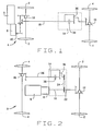
- Figure 1 is a schematic view of a front wheel drive automobile provided with a torque coupling constructed in accordance with and embodying the present invention;
- Figure 2 is a schematic view of a rear wheel drive automobile provided with the torque coupling;
- Figure 3 is a longitudinal sectional view of the torque coupling;
- Figure 4 is a kinematic diagram of the coupling;
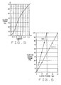
- Figure 5 is a graph showing the torque transferred by the clutch of the coupling as a function of the current in the magnetic clutch of the coupling;
- Figure 6 is a graph showing the torque transmitted through the coupling as a function of the torque transmitted through its clutch;
- Figure 7 is a longitudinal sectional view of a modified torque coupling;
- Figure 8 is a kinematic diagram of another modified torque coupling; and
- Figure 9 is a schematic view of an automobile with the torque coupling of the present invention located at each wheel.
- Corresponding reference characters indicate corresponding parts throughout the several views of the drawings.
- Referring now to the drawings, an automotive vehicle A (Fig. 1), such as an automobile (passenger car), a sports utility vehicle, a van, or even a truck, includes
primary driving wheels 2, which are the front road wheels; andsecondary driving wheels 4, which are the rear road wheels, It also includes amotor 6 which is either transversely or longitudinally mounted and is coupled to atransmission 8 which may be of the automatic type or manual type. Themotor 6 andtransmission 8 constitute a power unit which delivers torque through atransmission output shaft 10 which is basically the main shaft of thetransmission 8. Theshaft 10 of thetransmission 8 is connected to theprimary driving wheels 2 through aprimary differential 12. The connection is direct in the sense that no slippage occurs between theoutput shaft 10 and theprimary driving wheels 2. Theshaft 10 of thetransmission 8 is also connected to thesecondary driving wheels 4 through adrive shaft 18, atorque coupling 14, and asecondary differential 16, but the connection is indirect, inasmuch as thecoupling 14 accords a measure of slippage between thesecondary wheels 4 and thetransmission shaft 10, and likewise between thesecondary wheels 4 and theprimary wheels 2. The slippage accommodates small variations in velocity between the primary andsecondary wheels torque coupling 14, is located at or close to theprimary differential 12 and is connected to theshaft 10 of thetransmission 8 through thedrive shaft 18 which extends longitudinally through the vehicle A. - Another automotive vehicle B (Fig. 2) has essentially the same components as the vehicle A, except that they are organized differently. In the vehicle B, the
primary driving wheels 2 andprimary differential 12 are at the rear of the vehicle B, whereas thesecondary driving wheels 4 and thesecondary differential 16 are at the front of the vehicle B. Themotor 6 andtransmission 8, while being at the front of the vehicle B, are mounted longitudinally. Theshaft 10 of thetransmission 8 and theprimary differential 12 are connected through aprimary drive shaft 22. Thetorque coupling 14 is connected to theshaft 10 through achain 24, and thecoupling 14 is, in turn, connected to thesecondary differential 16 through asecondary drive shaft 26. - Each vehicle A and B possesses a variety of sensors which produce electrical signals that reflect the conditions under which the vehicle A or B operate, and those signals are transmitted to an onboard microprocessor which evaluates them and produces a signal that controls the
torque coupling 14. Indeed, the signal causes thetorque coupling 14 to apportion the torque delivered at theshaft 10 of thetransmission 8 between theprimary driving wheels 2 and thesecondary driving wheels 4 to enable the vehicle A or B to best respond to the driving conditions monitored by the sensors. Among the driving conditions monitored may be angular velocity of each of thewheels shaft 10 of thetransmission 8, position of the throttle for themotor 6, and position of the steering gear (steering angle). - The
torque coupling 14 apportions the torque delivered at thetransmission 8 between theprimary driving wheels 2 and thesecondary driving wheels 4 to best satisfy the conditions under which the vehicle A or B operate at the time. Thetorque coupling 14 includes (Fig. 3) an input member orshaft 32 connected to theshaft 10 of thetransmission 8, and an output member orshaft 34 connected to thesecondary differential 16. The twoshafts coupling 14 also contains aplanetary gear set 36 which is organized about the axis X, and is connected to both the input andoutput shafts coupling 14 has amagnetic particle clutch 38 which is also located around the axis X where it couples theinput shaft 32 to the planetary gear set 36 such that torque is transferred between the two if slippage occurs. Thecoupling 14 provides two torque transfer paths between theinput shaft 32 and the output shaft 34 (Fig. 4) - one a purely mechanical path that passes through the planetary gear set 36, and the other a clutch path which passes through both theclutch 38 and the planetary gear set 36. Most of the torque passes through the mechanical path, so it is the high torque path. The clutch path serves as the low torque path. - The
planetary gear set 36 includes (Fig. 3) asun gear 42 having astub shaft 44 which extends into theclutch 38. It also includes aring gear 46 to which theinput shaft 32 is coupled through aflange 48 andmachine screws 50, the latter of which extend through theclutch 38 and thus also couple theinput shaft 32 andring gear 46 to theclutch 38. In addition, the planetary gear set 36 has planet gears 52 which are located between thesun gear 42 andring gear 46 and engage both. Finally, the planetary gear set 36 has acarrier 54 which includesspindles 56 on which the planet gears 52 rotate. Thecarrier 54 is connected directly to theoutput shaft 34. Thegears carrier 54 constitute elements of theplanetary set 36. - The
magnetic particle clutch 38 includes (Fig. 3) anelectromagnet 60 which is captured between theflange 48 on theinput shaft 32 and thering gear 46 of the planetary gear set 36 and is secured to both with the machine screws 50. As a consequence, theinput shaft 32, itsflange 48, thering gear 46, and theelectromagnet 60 all rotate as a unit about the axis X. Theelectromagnet 60 has acylindrical surface 62 that is presented inwardly toward the axis X and further contains acoil 64 to which electrical current is supplied through a set ofstationary brushes 66 and a set ofslip rings 68 which rotate with theelectromagnet 60. - In addition to the
electromagnet 60 and itscoil 64, the clutch 38 has anarmature 70 which is located within theelectromagnet 60 and includes asleeve 72 that fits over thestub shaft 44 of the planetary gear set 36. The planetary gear set 36 is coupled to thestub shaft 44 through mating splines. Thearmature 70 also has acylindrical surface 74 which is presented outwardly away from the axis X and towardcylindrical surface 62 on theelectromagnet 60, there being a small gap "g" between the cylindrical surfaces between 62 and 74. Opening out of the ends of thearmature 70 areannular cavities 76 which containantifriction bearings 78 that support theelectromagnet 60 on thearmature 70. - The
bearings 78 fit around thesleeve 72 of thearmature 70 and theelectromagnet 60 in turn fits around thebearing 78. The arrangement is such that theinput shaft 32, thering gear 46, and theelectromagnet 60 rotate as a single unit about the axis X, and likewise thestub shaft 44,sun gear 42 andarmature 70 rotate as another unit about the axis X. Normally the two units rotate at slightly different angular velocities which are induced by the axle or tire design. When the clutch 38 engages, thestub shaft 44 and thesun gear 42 provide the required reaction torque to make the two units rotate together. - The clutch 38 contains
fine particles 80 of a ferrous substance that can be magnetized, and they exist in the gap "g". Thebearings 78 are isolated from themagnetic particles 80 byseals 82. When thecoil 64 is energized with electrical current, theparticles 80 become magnetized and connect theelectromagnet 60 with thearmature 70 such that torque can be transferred between the two, yet slippage between the two can occur as well. The amount of torque transferred depends solely on the amount of current conducted by thecoil 64, and is totally independent of the magnitude of the slippage or the temperature. Indeed, the relationship between torque and current, when plotted on Cartesian coordinates, closely approaches being linear (Fig. 5). The microprocessor to which the sensors feed signals which reflect the driving conditions of the vehicle A or B, controls the amount of current supplied to thecoil 64 of the clutch 38. However, the amount of current may also be controlled by a manually operated device such as a rheostat. - In the operation of the vehicle A or B, the motor 6 (Fig. 1) generates torque which is transferred through
transmission 8 which has the capacity to alter the torque, so that the torque delivered at theshaft 10 of thetransmission 8 may be different from that delivered by themotor 6. Some of the torque at thetransmission shaft 10 is delivered to theprimary driving wheels 2 through theprimary differential 10 without any slippage between thewheels 2 and thetransmission shaft 10. The remaining torque is delivered to thesecondary wheels 4 with some slippage between thetransmission shaft 10 and thesecondary wheels 4, and that slippage occurs within thetorque coupling 14. The total amount of torque delivered at theprimary wheels 2 and at thesecondary wheels 4 basically equals the torque in theshaft 10 of thetransmission 8. However, the apportionment of that torque between theprimary wheels 2 and thesecondary wheels 4 may not be equal, and under most driving conditions is not. The apportionment of torque between theprimary wheels 2 and thesecondary wheels 4 is dependent on the amount of current passing through thecoil 64 in the clutch 38 of thetorque coupling 12. The greater the current through thecoil 64, the higher the proportion of torque transferred to the secondary wheels 4 (Fig. 5). - The
shaft 10 of thetransmission 8, being coupled to theinput shaft 32 of thetorque coupling 14, rotates theinput shaft 32 and transfers torque to theinput shaft 32. Within thecoupling 14, the torque splits into two paths and then recombines, so that the torque in theoutput shaft 34 of thecoupling 14 essentially equals the torque in theinput shaft 32, at least when minimum slippage occurs in the clutch 38. In one path - the mechanical path - the torque passes from theinput shaft 32 and itsflange 48 to thering gear 46 of the planetary gear set 36, through planet gears 52, thence to theplanet carrier 54, and finally to theoutput shaft 34. For the other path - the clutch path - the torque passes from theinput shaft 32 and itsflange 48 to theelectromagnet 60 of the clutch 38, then through themagnetic particles 80 in the gap "g" between theelectromagnet 60 and thearmature 80, then to thesun gear 42 of the planetary set 36 through itsstub shaft 44, thence through the planet gears 52, and finally through thecarrier 54 to theoutput shaft 34. The hookups between the planetary gear set 36 and the clutch 38 are such that the mechanical path transfers more torque than the clutch path. - The division of torque between the two paths depends on the gear ratio U between the
ring gear 46 and the sun gear 42:
The higher the ratio U, the less the amount of torque transferred through the clutch path and conversely the more torque transferred through the mechanical path. The relationship may be demonstrated with a plot on Cartesian coordinates of the output torque for thecoupling 14; that is, the torque in theoutput shaft 34 against the torque in the clutch 38 (Fig. 6). - Referring to the two plots (Figs. 5 & 6), a reduction of the current in the
coil 64 of the clutch 38 will reduce the torque transmitted through the clutch path, and that in turn will reduce the total torque delivered through theoutput shaft 34 to thesecondary wheels 4. Since the torque in theoutput shaft 34 generally equals the torque in theinput shaft 32, a lesser amount of torque is diverted from theshaft 10 of thetransmission 8 to theinput shaft 32 of thecoupling 14, leaving a greater amount to be transferred to theprimary driving wheels 2. Conversely, when the current in thecoil 64 of the clutch 38 increases, the clutch 38 transfers more torque which translates into more torque in the clutch path and a proportionally greater torque at theoutput shaft 34 and theinput shaft 32. The greater demand for torque by theinput shaft 32 leaves less torque for theprimary drive wheels 2. Thus, the amount of current passing through thecoil 64 of themagnetic particle clutch 38 determines the proportion of the total torque at thetransmission shaft 10 which is diverted through thetorque coupling 14 which is the amount of torque delivered to thesecondary wheels 4. The remaining torque from thetransmission shaft 10 goes to theprimary wheels 2. In short, the current in thecoil 64 of themagnetic particle clutch 38 controls the division of torque betweenprimary wheels 2 and thesecondary wheels 4, and that current is the only control parameter for the clutch 38. This is in contrast to conventional plate-type clutches in which the pressure applied to the plates, the amount of slippage in the clutch and other variables, such as temperature, control the amount of torque transferred through such clutches. Moreover, the relationship between torque and current in the present invention is nearly linear, which affords good control of the allocation of torque between theprimary driving wheels 2 and thesecondary wheels 4. - The clutch 38 sees some slippage under typical driving conditions, with the
input shaft 32 rotating slightly faster than theoutput shaft 34, but the difference in angular velocities is not substantial and produces only a very small dissipation of power. - Most of the torque transferred through the
torque coupling 12 passes through the mechanical path and relatively little through the clutch path. Hence, the clutch 38 may be relatively compact and light in weight. Moreover, thecoil 64 and the current passing through it controls torque transferred through thecoupling 14, which is considerably less complex than pistons, ball ramps, and other devices used in plate-type clutches. - The sensors in the vehicle A or B monitor driving conditions experienced by the vehicle at any instant and send signals, which reflect those operating conditions, to the microprocessor. The microprocessor in turn controls the amount of current that passes through the
coil 64 of the clutch 38, so that the torque transferred to theprimary wheels 2 and the torque transferred to thesecondary wheels 4 best suits those driving conditions. - A modified torque coupling 86 (Fig. 7) relies on the same kinematic principle as the coupling 14 (Fig. 4), but possesses a somewhat different configuration. In the modified
coupling 86, theinput shaft 32 extends through thesleeve 72 on thearmature 70 for the clutch 38, and also through thesun gear 42 of theplanetary set 36. While theshaft 32 andsleeve 72 are engaged through mating splines, thesun gear 42 is free to rotate around theshaft 32. Beyond thesun gear 42, theinput shaft 32 is connected to thering gear 46 through aflange 88. Thesun gear 42, on the other hand, is coupled to anotherflange 90 which in turn is secured to theelectromagnet 60 of the clutch 38 withmachine screws 92 that pass through theelectromagnet 60 and thread into theflange 90. Theoutput shaft 34 is coupled to adrum 94 within which the planetary set 36 rotates, and thedrum 94 is connected to thecarrier 54 of theplanetary set 36. - Another modified coupling 100 (Fig. 8) utilizes essentially the
same clutch 38, but relies on aplanetary set 102 that operates on a kinematic principle somewhat different from thesets 36 for thecouplings planetary set 102 includes two sun gears 104 and 106. While the two sun gears 104 and 106 rotate about the axis X, they are detached from each other, with thegear 104 being connected to theinput shaft 32 and thegear 106 being connected to theoutput shaft 34. The sun gears 104 and 106 mesh withplanetary gears carrier 112 havingspindles 114. Indeed, theplanetary gears planetary gear 108 and a singleplanetary gear 110 located around asingle spindle 114 of thecarrier 112. Theplanetary gears spindle 114. Thecarrier 112 is attached to theelectromagnet 60 of the clutch 38, whereas thearmature 70 of the clutch 38 is attached to thesun gear 104 and of course to theinput shaft 32 as well. Thegears carrier 112 all constitute elements of theplanetary set 102. - In the operation of the
coupling 100, the torque applied at theinput shaft 32 within thecoupling 100 splits into a mechanical path and a clutch path and then recombines so that the torque at theoutput shaft 34 is essentially the same as the torque applied to theinput shaft 32. In the mechanical path, the torque passes from thesun gear 104 to the planet gears 108 and likewise to the planet gears 110 to which thegears 108 are joined, and thence to theother sun gear 106 and theoutput shaft 34 to which it is connected. In the clutch path, the torque passes from theinput shaft 32 to thearmature 70 of themagnetic particle clutch 38 and thence to theelectromagnet 60 of the clutch 38. Theelectromagnet 60, being coupled to the planet gears 108 and 110 through thecarrier 112, causes thecarrier 112 and planet gears 108 and 110 to rotate about the axis X and thus transfer torque from theelectromagnet 60 of the clutch 38 to thesun gear 106, with which theplanet gear 110 is engaged, and of course to theoutput shaft 34 to which thesun gear 106 is connected. - Whereas a
single torque coupling 14 apportions torque between theprimary wheels 2 and thesecondary wheels 4 in the vehicles A and B, multiple coupling 14 - or for that mattermultiple couplings 86 or 100 - may be used to apportion torque among all fourwheels 2 and of 4 of still another vehicle C (Fig. 9). In the vehicle C, eachwheel own axle shaft 120, and eachaxle shaft 120 is connected to theoutput shaft 34 of aseparate torque coupling 14. The twotorque couplings 14 at the front of the vehicle C have theirinput shafts 32 connected to acommon cross shaft 122. The same holds true at the rear of the vehicle where theinput shafts 32 for the tworear couplings 14 are connected to anothercross shaft 124. Both crossshafts shaft 10 of the transmission without interveningdifferentials coupling 14. In the operation of the vehicle C, the torque delivered at theshaft 10 of thetransmission 8 is transferred to thecross shafts transmission shaft 10 and either of thecross shafts couplings 14 control the torque delivered to theindividual wheels transmission shaft 10 is apportioned amongst the fourwheels electromagnets 60 of theclutches 38 for the fourcouplings 14. For example, if one of thewheels 4 begins to slip, the current passing through the clutch 38 for thecoupling 14 at thatwheel 4 may be reduced, and this has the effect of transferring more torque to the remainingwheels - Other variations are possible and they may employ the same planetary sets 36 or 102 with different hookups. Irrespective of the hookup, the arrangement should split the torque into a mechanical path and a clutch path, with most of the torque passing through the mechanical path. In the same vein, the
input shaft 32 and output shaft may be reversed, so that torque is applied to theshaft 34 and delivered from theshaft 32. Moreover, the planetary sets 36, 102 need not rely on gearing, but instead on friction surfaces, thus becoming traction devices or drives. Actually, thecouplings secondary wheels 4 of a vehicle. They have applications in machinery other than that in automotive vehicles, and even in automotive vehicles, the couplings may be used in different locations.
Claims (7)
- A torque coupling (14, 86, 100) comprising:a first torque member (32) through which torque is applied to the coupling;a second torque member (34) through which torque is delivered from the coupling;a magnetic particle clutch (38) having first and second clutch members (60 ,70) which are capable of rotating at different angular velocities and an electric coil (64), the clutch having the capability of transferring torque between the clutch members when the clutch members rotate at different angular velocities, with the amount of torque transferred through the clutch being dependent on the current passing through the coil (64), the first clutch member (60) being connected to one of the torque members (32, 34); anda planetary gear set (36, 102) organized about the same axis and coupled to the clutch and to the first and second torque members (32, 34) such that torque transfers between the first and second members in two paths, one of which is a clutch path that includes the clutch (38) and the other of which path is a mechanical path that does not include the clutch, the planetary gear set (36, 102) including first, second, third and fourth elements organized about the axis, the first element being connected to the first clutch member (60) and to said one of the torque members, the second element being connected to the second clutch member (70) such that all of the torque transferred through the clutch passes through the second element, the third element being connected to the other torque member, and the fourth element being connected between the first element and the second element and between the second element and the third element, the elements of the planetary gear set being configured such that most of the torque that is transferred between the first and second torque members transfers through the mechanical path.
- A torque coupling according to claim 1 wherein the clutch members (60, 70) rotate about the axis around which the planetary set is organized; and wherein the second planetary element is a sun gear (42), the first planetary element is a ring gear (46) that surrounds the sun gear, the fourth planetary element is a planet gear (52) that is located between and engages the sun and ring gears, and the third planetary element is a carrier (54) that rotates about the axis and provides an axis about which the planet gear (52) revolves.
- A torque coupling according to claim 1 and further comprising means for varying the current in the electric coil (64) of the clutch (38) to control the amount of torque transferred through the clutch and through the coupling.
- A torque coupling according to claim 1 wherein the first element is a sun element (104) which rotates about the axis; wherein the third element is also a sun element (106) which rotates about the axis; wherein the fourth element is a planetary element (114) which engages with the two sun elements (104, 106); and wherein the second element is a carrier element (112) about which the fourth element rotates.
- In combination with the torque coupling of claim 1, an automotive vehicle having a power unit, first wheels connected directly to the power unit, and second wheels connected indirectly to the power unit through the torque coupling set forth in claim 1.
- In combination with the torque coupling of claim 1, an automotive vehicle including a power unit; wheels which align generally along their axes across the vehicle, and a separate coupling as set forth in claim 1 connected between each of the aligned wheels and the power unit such that torque is transferred to each of the aligned wheels through the separate torque coupling for that wheel.
- A torque coupling according to claim 1 wherein the second element is a sun element (42) which rotates about the axis; wherein the first element is a ring element (46) located around the axis; wherein the fourth element is a planetary element (52) located between and engaged with the sun and ring elements (42, 46); and wherein the third element is a carrier element (54) which rotates about the axis and on which the planetary elements (52) rotate.
Applications Claiming Priority (3)
| Application Number | Priority Date | Filing Date | Title |
|---|---|---|---|
| US6312 | 1998-01-13 | ||
| US10/006,312 US6712730B2 (en) | 2001-12-06 | 2001-12-06 | Active torque bias coupling |
| PCT/US2002/024229 WO2003049966A1 (en) | 2001-12-06 | 2002-07-30 | Active torque bias coupling |
Publications (2)
| Publication Number | Publication Date |
|---|---|
| EP1451032A1 EP1451032A1 (en) | 2004-09-01 |
| EP1451032B1 true EP1451032B1 (en) | 2006-09-13 |
Family
ID=21720277
Family Applications (1)
| Application Number | Title | Priority Date | Filing Date |
|---|---|---|---|
| EP02752635A Expired - Lifetime EP1451032B1 (en) | 2001-12-06 | 2002-07-30 | Active torque bias coupling |
Country Status (7)
| Country | Link |
|---|---|
| US (1) | US6712730B2 (en) |
| EP (1) | EP1451032B1 (en) |
| JP (1) | JP2005511996A (en) |
| KR (1) | KR20040085138A (en) |
| AU (1) | AU2002366545A1 (en) |
| DE (1) | DE60214757T2 (en) |
| WO (1) | WO2003049966A1 (en) |
Cited By (1)
| Publication number | Priority date | Publication date | Assignee | Title |
|---|---|---|---|---|
| WO2008146137A1 (en) * | 2007-05-31 | 2008-12-04 | Eaton Corporation | Torque transfer device and system |
Families Citing this family (19)
| Publication number | Priority date | Publication date | Assignee | Title |
|---|---|---|---|---|
| AU2003249183A1 (en) * | 2002-07-31 | 2004-02-16 | The Timken Company | Torque split hydraulic coupling between transmission and secondary driving axle with torque modulation and locking capabilities |
| US20060172847A1 (en) * | 2005-01-28 | 2006-08-03 | Mircea Gradu | Torque-vectoring defferential |
| US7459816B2 (en) * | 2004-08-11 | 2008-12-02 | Tai-Her Yang | Bidirectional coupling device with variable transmission characteristics |
| US7334670B2 (en) * | 2004-09-08 | 2008-02-26 | Gm Global Technology Operations, Inc. | Torque vectoring differential for controlling vehicle stability |
| US7410017B2 (en) * | 2004-11-30 | 2008-08-12 | The Timken Company | Electric drive axle |
| US20080230296A1 (en) * | 2005-08-09 | 2008-09-25 | The Timken Company | Front to Rear Torque Vectoring Axle with Overspaced Capability for Vehicle Dynamic Control Systems |
| US7361114B2 (en) * | 2005-09-09 | 2008-04-22 | Eaton Corporation | Vehicle differential including pump with variable-engagement clutch |
| US7549941B2 (en) * | 2005-09-09 | 2009-06-23 | Eaton Corporation | Vehicle differential including pump with variable-engagement clutch |
| US7727941B2 (en) * | 2005-09-22 | 2010-06-01 | Ecolab Inc. | Silicone conveyor lubricant with stoichiometric amount of an acid |
| DE102005049366A1 (en) * | 2005-10-11 | 2007-04-19 | Mbm Technologie Gmbh | Motor-driven vehicle with a transmission for an accessory |
| US7600598B2 (en) * | 2006-05-05 | 2009-10-13 | Ford Global Technologies, Llc | Biasing drive torque to a secondary axle in a motor vehicle powertrain |
| CN101573247B (en) * | 2006-11-03 | 2014-03-19 | 玛格纳动力传动系统股份及两合公司 | Torque transmission unit |
| CA2724388C (en) | 2008-05-15 | 2017-05-23 | Ker-Train Holdings Ltd. | Concentric v-groove coupling |
| US8360931B2 (en) * | 2009-07-22 | 2013-01-29 | Arvinmeritor Technology, Llc | Power take-off clutch synchronizing system |
| WO2015035006A2 (en) * | 2013-09-05 | 2015-03-12 | Eaton Corporation | Variable output centrifugal pump |
| GB2532980A (en) * | 2014-12-04 | 2016-06-08 | Black & Decker Inc | Planetary gear system |
| CN105134937B (en) * | 2015-09-16 | 2017-07-18 | 湖南中德汽车自动变速器股份有限公司 | A kind of power compensation type power shifting automatic transmission and method for changing speed |
| GB2545689A (en) * | 2015-12-22 | 2017-06-28 | Jaguar Land Rover Ltd | System for providing four wheel drive in a vehicle |
| US11998474B2 (en) | 2018-03-15 | 2024-06-04 | Coloplast A/S | Apparatus and methods for navigating ostomy appliance user to changing room |
Family Cites Families (28)
| Publication number | Priority date | Publication date | Assignee | Title |
|---|---|---|---|---|
| US2709928A (en) * | 1951-01-31 | 1955-06-07 | Giddings & Lewis | Variable speed transmission |
| US4037694A (en) * | 1975-07-21 | 1977-07-26 | Rockwell International Corporation | Drive axle outer end with brake and gearing |
| US4142615A (en) * | 1976-02-13 | 1979-03-06 | Caterpillar Tractor Co. | Wheel drive assembly |
| JPS5715019A (en) | 1980-06-27 | 1982-01-26 | Fuji Heavy Ind Ltd | Changeover device for 2, 4 wheel drive in 4-wheel drive vehicle |
| JPS57104410A (en) * | 1980-12-22 | 1982-06-29 | Toyo Umpanki Co Ltd | Driving shaft device |
| JPS59190522A (en) | 1983-04-08 | 1984-10-29 | Toyota Motor Corp | Controller of magnetic powder system solenoid clutch for vehicle |
| AT382826B (en) | 1984-10-01 | 1987-04-10 | Steyr Daimler Puch Ag | DRIVE ARRANGEMENT FOR A MOTOR VEHICLE |
| DE3507491A1 (en) | 1985-03-02 | 1986-09-04 | Dr.Ing.H.C. F. Porsche Ag, 7000 Stuttgart | 4WD DRIVE FOR A MOTOR VEHICLE |
| US4860612A (en) | 1985-04-01 | 1989-08-29 | Dana Corporation | Vehicle torque transfer case for a four wheel drive system |
| JPS6231532A (en) | 1985-08-02 | 1987-02-10 | Toyota Motor Corp | Control device for vehicle magnetic powder type electromagnetic clutch |
| JP2517911B2 (en) | 1986-06-10 | 1996-07-24 | トヨタ自動車株式会社 | Control method of four-wheel drive device |
| JPS639735A (en) | 1986-06-30 | 1988-01-16 | Mitsubishi Electric Corp | Magnetic-particle-type coupling device |
| JPH0365472A (en) * | 1989-07-31 | 1991-03-20 | Komatsu Ltd | System for steering, gear-changing and driving of crawler-type tractor |
| JPH0370684A (en) * | 1989-08-11 | 1991-03-26 | Komatsu Ltd | Hydraulic steering device with variable displacement oil hydraulic motor |
| US4995862A (en) | 1989-08-21 | 1991-02-26 | Arocha Henry F | Interaxle transfer mechanism for four wheel drive vehicles |
| JP3192768B2 (en) | 1992-09-03 | 2001-07-30 | 日産自動車株式会社 | Comprehensive control system for front and rear wheel drive force distribution and traction |
| US5595214A (en) | 1993-02-10 | 1997-01-21 | Asha Corporation | Hydraulic coupling for vehicle drivetrain |
| SE501036C2 (en) | 1993-03-15 | 1994-10-24 | Ipumatic Ab | Device for torque transmission between two rotatable shafts |
| US5733222A (en) | 1995-06-02 | 1998-03-31 | Honda Giken Kogyo Kabushiki Kaisha | Power transmission apparatus |
| SE504642C2 (en) | 1995-07-14 | 1997-03-24 | Ipumatic Ab | Device for transferring torque between two rotatable shafts |
| US5713444A (en) * | 1995-09-18 | 1998-02-03 | Schroeder; Karl S. | Electromagnetic brake/clutch |
| US5704444A (en) | 1995-12-11 | 1998-01-06 | Borg-Warner Automotive, Inc. | Adaptive vehicle drive system for extreme operating conditioning |
| JP3234145B2 (en) * | 1996-02-05 | 2001-12-04 | 本田技研工業株式会社 | Power transmission device cooling structure |
| US5779013A (en) * | 1996-07-18 | 1998-07-14 | New Venture Gear, Inc. | Torque transfer apparatus using magnetorheological fluids |
| US6142905A (en) | 1997-03-21 | 2000-11-07 | New Venture Gear, Inc. | Full-time four-wheel drive transmission with limited slip clutch |
| US6158303A (en) | 1997-03-21 | 2000-12-12 | Mazda Motor Corporation | Transfer case for four wheel drive vehicle |
| US6098770A (en) | 1999-03-19 | 2000-08-08 | Borgwarner Inc. | Clutch assembly having reaction force circuit |
| US6102827A (en) * | 1999-04-28 | 2000-08-15 | Caterpillar Inc. | Clutch assembly with a planetary gear set |
-
2001
- 2001-12-06 US US10/006,312 patent/US6712730B2/en not_active Expired - Fee Related
-
2002
- 2002-07-30 DE DE60214757T patent/DE60214757T2/en not_active Expired - Lifetime
- 2002-07-30 JP JP2003551002A patent/JP2005511996A/en active Pending
- 2002-07-30 EP EP02752635A patent/EP1451032B1/en not_active Expired - Lifetime
- 2002-07-30 WO PCT/US2002/024229 patent/WO2003049966A1/en active IP Right Grant
- 2002-07-30 AU AU2002366545A patent/AU2002366545A1/en not_active Abandoned
- 2002-07-30 KR KR10-2004-7008650A patent/KR20040085138A/en not_active Application Discontinuation
Cited By (1)
| Publication number | Priority date | Publication date | Assignee | Title |
|---|---|---|---|---|
| WO2008146137A1 (en) * | 2007-05-31 | 2008-12-04 | Eaton Corporation | Torque transfer device and system |
Also Published As
| Publication number | Publication date |
|---|---|
| DE60214757T2 (en) | 2007-09-20 |
| DE60214757D1 (en) | 2006-10-26 |
| WO2003049966A1 (en) | 2003-06-19 |
| EP1451032A1 (en) | 2004-09-01 |
| KR20040085138A (en) | 2004-10-07 |
| JP2005511996A (en) | 2005-04-28 |
| AU2002366545A1 (en) | 2003-06-23 |
| US20030109351A1 (en) | 2003-06-12 |
| US6712730B2 (en) | 2004-03-30 |
Similar Documents
| Publication | Publication Date | Title |
|---|---|---|
| EP1451032B1 (en) | Active torque bias coupling | |
| US6238317B1 (en) | Full-time four-wheel drive transmission with limited slip clutch | |
| US7186199B1 (en) | Torque vectoring gear drive apparatus | |
| US5720688A (en) | Full-time transfer case with synchronized dual planetary gear reduction unit | |
| US7547265B2 (en) | Variable biasing differential | |
| US6645108B1 (en) | Active torque bias system and controls | |
| US5902205A (en) | Full-time transfer case with integrated planetary gearset and biasing clutch | |
| US5853342A (en) | Offset transfer case | |
| US20030199359A1 (en) | Differential gear | |
| US20050070392A1 (en) | Two-speed transfer case with ball-ramp clutch and single motor activator/shift system | |
| EP1470015B1 (en) | Transfer case with enhanced torque bias capability | |
| EP0865954A2 (en) | On-demand four-wheel drive transmission with transfer clutch | |
| US20030171182A1 (en) | Alex module with axle shaft electronic management | |
| US6755762B2 (en) | Axle center with active torque bias control | |
| US5967930A (en) | Adapter for transfer cases | |
| US7422537B2 (en) | Torque split hydraulic coupling between transmission and secondary driving axle with torque modulation and locking capabilities | |
| US20080230296A1 (en) | Front to Rear Torque Vectoring Axle with Overspaced Capability for Vehicle Dynamic Control Systems | |
| JPH04372427A (en) | Four-wheel drive unit and control thereof | |
| CA2463086C (en) | Full-time transfer case with integrated planetary gearset | |
| WO1997037152A1 (en) | Offset transfer case | |
| EP0865955A2 (en) | On-demand four-wheel drive transmission with lock-out clutch |
Legal Events
| Date | Code | Title | Description |
|---|---|---|---|
| PUAI | Public reference made under article 153(3) epc to a published international application that has entered the european phase |
Free format text: ORIGINAL CODE: 0009012 |
|
| 17P | Request for examination filed |
Effective date: 20040622 |
|
| AK | Designated contracting states |
Kind code of ref document: A1 Designated state(s): AT BE BG CH CY CZ DE DK EE ES FI FR GB GR IE IT LI LU MC NL PT SE SK TR |
|
| AX | Request for extension of the european patent |
Extension state: AL LT LV MK RO SI |
|
| GRAP | Despatch of communication of intention to grant a patent |
Free format text: ORIGINAL CODE: EPIDOSNIGR1 |
|
| GRAS | Grant fee paid |
Free format text: ORIGINAL CODE: EPIDOSNIGR3 |
|
| GRAA | (expected) grant |
Free format text: ORIGINAL CODE: 0009210 |
|
| AK | Designated contracting states |
Kind code of ref document: B1 Designated state(s): DE FR GB SE |
|
| REG | Reference to a national code |
Ref country code: GB Ref legal event code: FG4D |
|
| REF | Corresponds to: |
Ref document number: 60214757 Country of ref document: DE Date of ref document: 20061026 Kind code of ref document: P |
|
| REG | Reference to a national code |
Ref country code: SE Ref legal event code: TRGR |
|
| ET | Fr: translation filed | ||
| PGFP | Annual fee paid to national office [announced via postgrant information from national office to epo] |
Ref country code: SE Payment date: 20070615 Year of fee payment: 6 |
|
| PLBE | No opposition filed within time limit |
Free format text: ORIGINAL CODE: 0009261 |
|
| STAA | Information on the status of an ep patent application or granted ep patent |
Free format text: STATUS: NO OPPOSITION FILED WITHIN TIME LIMIT |
|
| 26N | No opposition filed |
Effective date: 20070614 |
|
| PGFP | Annual fee paid to national office [announced via postgrant information from national office to epo] |
Ref country code: FR Payment date: 20070611 Year of fee payment: 6 |
|
| EUG | Se: european patent has lapsed | ||
| REG | Reference to a national code |
Ref country code: FR Ref legal event code: ST Effective date: 20090331 |
|
| PG25 | Lapsed in a contracting state [announced via postgrant information from national office to epo] |
Ref country code: FR Free format text: LAPSE BECAUSE OF NON-PAYMENT OF DUE FEES Effective date: 20080731 |
|
| PG25 | Lapsed in a contracting state [announced via postgrant information from national office to epo] |
Ref country code: SE Free format text: LAPSE BECAUSE OF NON-PAYMENT OF DUE FEES Effective date: 20080731 |
|
| PGFP | Annual fee paid to national office [announced via postgrant information from national office to epo] |
Ref country code: GB Payment date: 20110721 Year of fee payment: 10 |
|
| GBPC | Gb: european patent ceased through non-payment of renewal fee |
Effective date: 20120730 |
|
| PG25 | Lapsed in a contracting state [announced via postgrant information from national office to epo] |
Ref country code: GB Free format text: LAPSE BECAUSE OF NON-PAYMENT OF DUE FEES Effective date: 20120730 |
|
| PGFP | Annual fee paid to national office [announced via postgrant information from national office to epo] |
Ref country code: DE Payment date: 20140721 Year of fee payment: 13 |
|
| REG | Reference to a national code |
Ref country code: DE Ref legal event code: R119 Ref document number: 60214757 Country of ref document: DE |
|
| PG25 | Lapsed in a contracting state [announced via postgrant information from national office to epo] |
Ref country code: DE Free format text: LAPSE BECAUSE OF NON-PAYMENT OF DUE FEES Effective date: 20160202 |