EP1450224A1 - Numerical control machine and method with misalignment correction - Google Patents

Numerical control machine and method with misalignment correction Download PDF

Info

Publication number
EP1450224A1
EP1450224A1 EP04250870A EP04250870A EP1450224A1 EP 1450224 A1 EP1450224 A1 EP 1450224A1 EP 04250870 A EP04250870 A EP 04250870A EP 04250870 A EP04250870 A EP 04250870A EP 1450224 A1 EP1450224 A1 EP 1450224A1
Authority
EP
European Patent Office
Prior art keywords
axis
rotation
misalignment
machine
numerical control
Prior art date
Legal status (The legal status is an assumption and is not a legal conclusion. Google has not performed a legal analysis and makes no representation as to the accuracy of the status listed.)
Ceased
Application number
EP04250870A
Other languages
German (de)
French (fr)
Inventor
Toshiaki Otsuki
Hideo Ogino
Takafumi c/o FANUC Dai3virakaramatsu Sasaki
Current Assignee (The listed assignees may be inaccurate. Google has not performed a legal analysis and makes no representation or warranty as to the accuracy of the list.)
Fanuc Corp
Original Assignee
Fanuc Corp
Priority date (The priority date is an assumption and is not a legal conclusion. Google has not performed a legal analysis and makes no representation as to the accuracy of the date listed.)
Filing date
Publication date
Application filed by Fanuc Corp filed Critical Fanuc Corp
Publication of EP1450224A1 publication Critical patent/EP1450224A1/en
Ceased legal-status Critical Current

Links

Images

Classifications

    • GPHYSICS
    • G05CONTROLLING; REGULATING
    • G05BCONTROL OR REGULATING SYSTEMS IN GENERAL; FUNCTIONAL ELEMENTS OF SUCH SYSTEMS; MONITORING OR TESTING ARRANGEMENTS FOR SUCH SYSTEMS OR ELEMENTS
    • G05B19/00Program-control systems
    • G05B19/02Program-control systems electric
    • G05B19/18Numerical control [NC], i.e. automatically operating machines, in particular machine tools, e.g. in a manufacturing environment, so as to execute positioning, movement or co-ordinated operations by means of program data in numerical form
    • G05B19/404Numerical control [NC], i.e. automatically operating machines, in particular machine tools, e.g. in a manufacturing environment, so as to execute positioning, movement or co-ordinated operations by means of program data in numerical form characterised by control arrangements for compensation, e.g. for backlash, overshoot, tool offset, tool wear, temperature, machine construction errors, load, inertia
    • GPHYSICS
    • G05CONTROLLING; REGULATING
    • G05BCONTROL OR REGULATING SYSTEMS IN GENERAL; FUNCTIONAL ELEMENTS OF SUCH SYSTEMS; MONITORING OR TESTING ARRANGEMENTS FOR SUCH SYSTEMS OR ELEMENTS
    • G05B2219/00Program-control systems
    • G05B2219/30Nc systems
    • G05B2219/50Machine tool, machine tool null till machine tool work handling
    • G05B2219/50297Compensation of positioning error due to a-axis, b-axis tool rotation

Definitions

  • the present invention relates to a numerical control device for controlling a machine having an axis of rotation other than an axis of linear motion, and a numerical control method thereof.
  • Machines having an axis of rotation other than an axis of linear motion are used as machine tools that work the free form surfaces of molds and the like.
  • Five-axis machine tools equipped with two rotating axes and linearly moving axes X, Y, and Z are known. Because such machines are equipped with rotating axes, tools can be tilted to work in any direction with respect to the work surface of the workpiece in association with the rotation of these rotating axes. Because the amount of compensation to the tool length changes due to the tilting of the tool, work is performed while compensating for the tool length (Refer to Japanese Patent Application Laid-open Nos. H3-109606 and H5-100723, for example).
  • Japanese Patent Application Laid-open No. 2001-269839 for corrects the spindle head error in a five-axis machine tool equipped with members that rotate about the linearly moving axes X, Y, and Z, with a C-axis, which is the axis of rotation about the vertical axis line, and with a B'-axis inclined at a prescribed angle with respect to the C-axis, by fixing the B'-axis at a prescribed angle; measuring the spindle end position for each prescribed swivel angle when rotating a member about the C-axis; performing a multiple regression analysis with a regression equation and computing the swivel plane from this measurement data; computing the axial vector of the C-axis member; fixing the C-axis at a prescribed angle; measuring the spindle end position at every prescribed swivel angle when swiveling a member about the B-axis; performing a multiple regression analysis with a regression equation, computing the swive
  • the center position error of the axis of rotation and the tilt error are taken into consideration, and the error of the spindle head position is corrected, but with this method, one of two axes of rotation is fixed, a multiple regression analysis is performed with a regression equation on the basis of the data obtained from measuring the spindle end position for each position in which the other axis is rotated at a prescribed angle, the swivel plane is computed, the axial vector is computed, the spindle end position is computed in a state in which these axial vectors are swiveled; the difference with the original spindle position is taken to be the spindle head position error; and the NC coordinate system is offset in accordance with the spindle head position error, resulting in complicated processing.
  • the numerical control device relates to a numerical control device for controlling a machine having an axis of linear motion and at least one axis of rotation on a tool head or a table.
  • This numerical control device has means for obtaining a machine position to which a machine should actually move so that the relation between a workpiece and a tool as found when there is no mechanical error is maintained on the basis of a reference position at which there is no mechanical error in the axis of rotation and an amount of misalignment of an actual axis of rotation from the reference position, and/or on the basis of a reference position at which there is no mechanical error in the turning center of the spindle and an amount of misalignment of an actual turning center of the spindle from the reference position of the turning center of the spindle; and drive control means for driving the axis of rotation and the axis of linear motion to the machine position obtained by the machine position obtaining means.
  • This numerical control device may take the following embodiments.
  • the machine is one in which the tool head rotates about at least one axis, one in which the table rotates about at least one axis, or one in which the tool head and the table rotate.
  • the amount of misalignment is set by a parameter in the numerical control device.
  • the amount of misalignment is delivered to the numerical control device by a signal from the machine to the numerical control device, or is reported to the numerical control device by a signal from external equipment to the numerical control device.
  • the numerical control method relates to a numerical control method that uses a numerical control device for a machine having an axis of linear motion and at least one axis of rotation on a tool head or a table.
  • This numerical control method has a step of obtaining a machine position to which a machine should actually move so that the relation between a workpiece and a tool as found when there is no mechanical error is maintained on the basis of a reference position at which there is no mechanical error in the axis of rotation and an amount of misalignment of an actual axis of rotation from the reference position, and/or on the basis of a reference position at which there is no mechanical error in the turning center of the spindle and an amount of misalignment of an actual turning center of the spindle from the reference position of the turning center of the spindle; and a step of moving the axis of linear motion and the axis of rotation to the machine position thus obtained.
  • This numerical control method may take the following embodiments.
  • the machine is one in which a tool head rotates about at least one axis
  • the method has a step of correcting the tool length vector on the basis of a reference position at which there is no mechanical error in the axis of rotation and an amount of misalignment of an actual axis of rotation from the reference position, and/or a reference position at which there is no mechanical error in the turning center of the spindle, an amount of misalignment of an actual turning center of the spindle from the reference position of the turning center of the spindle, and instruction for the axis of rotation; and a step of adding the instruction position vector to the corrected tool length vector to obtain the machine position.
  • the machine is one in which a table rotates about at least one axis, and the method has a step of adding an offset of the origin of a table coordinate system to an instruction position value in the table coordinate system and computing the instruction position in the machine coordinate system; and a step of correcting the misalignment of the instruction position in the machine coordinate system on the basis of a reference position at which there is no mechanical error in the axis of rotation, an amount of misalignment of the actual axis of rotation from the reference position, and the instruction position for the axis of rotation, obtaining a rotation position to which the axis of rotation has rotated according to the instruction, and adding the tool length vector to the position to obtain the machine position.
  • the machine is one in which a tool head and a table rotate, and the method has a step of adding an offset of the origin of a table coordinate system to a position instruction in the table coordinate system and obtaining an instruction position in the machine coordinate system; a step of obtaining an instruction position for which the misalignment has been corrected on the basis of an amount of misalignment of the actual axis of rotation provided to the table from a reference position at which there is no mechanical error in the axis of rotation and an instruction position for the axis of rotation; a step of obtaining an attitude of the tool for which misalignment has been corrected on the basis of an amount of misalignment of the actual axis of rotation provided to the tool head from a reference position at which there is no mechanical error in the axis of rotation and the instruction position of the axis of rotation, in addition to a tool vector; and a step of obtaining a machine position on the basis of an instruction position for which the misalignment has been corrected and an attitude of the tool for which the misalign
  • the amount of misalignment is delivered to the numerical control device by a parameter setting in the numerical control device, a signal from the machine, or a signal from external equipment.
  • a numerical control device and a numerical control method that are simple, are capable of high precision working, and can perform continuous working that includes movement of an axis of rotation, even when the center of an axis of rotation diverges or is inclined from the original position, or when the turning center of the spindle diverges or is inclined from the original position in a numerical control device for controlling a machine that includes the axis of rotation.
  • Machines that have axes of rotation exist in multiple types (structural differences).
  • the embodiments in which the present invention is adapted to each type of machine are demonstrated with applications to three types of machines, namely, tool head rotary machines, table rotary machines, and tool head and table rotary machines, and the basic principles of the present invention comprising these three embodiments are described below.
  • the first embodiment of the present invention is a tool head rotary machine having orthogonal axes of linear motion X, Y, and Z; the tool head is provided with an A-axis (rotating about the X-axis) and a C-axis (rotating bout the Z-axis) as axes of rotation; the C-axis is the master axis; the A-axis operates on the C-axis; and the tool direction is the Z-axis direction when the angle of the A- and C-axes is "0.”
  • the tool length vector Vt -H (0, 0, h, 1) T and the workpiece origin offset WO -H (WOx -H , WOy -H , WOz -H , 1) T when the angle of rotation of the A-axis and the C-axis is "0" are given as the initial conditions.
  • the symbol " T " in a homogeneous coordinate system hereinafter refers to transposition.
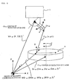
  • FIG. 1 is a diagram illustrating the calculation of a machine position in a machine having axes of rotation A and C when there is no misalignment.
  • Reference numerals 1 and 2 denote a tool head and a tool.
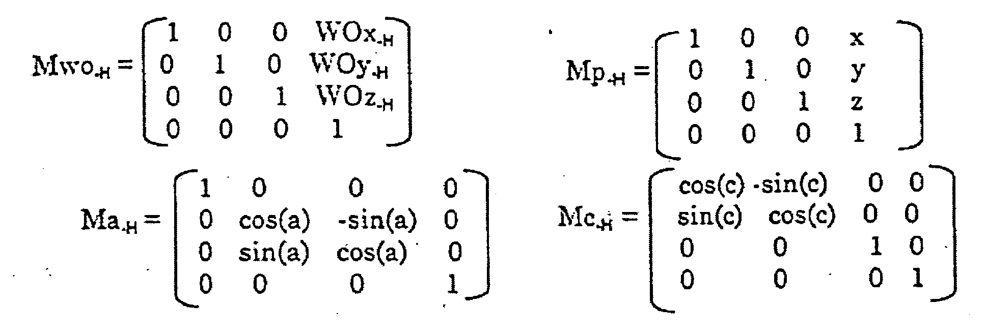
  • Vm -H Mwo -H * Mp -H * Mc -H * Ma -H * Vt -H
  • Mwo -H , Mp -H , Mc -H , Ma -H are transformation matrices, and are as follows.
  • matrix Mwo -H is determined by the amount of offset WO -H (WOx -H , WOy -H , WOz -H , 1) T from the workpiece origin that is given as the initial condition, and matrix Mp -H is computed with the positional instruction value P (x, y, z).
  • Matrix Mc -H is computed with the aid of the instruction c for the C-axis of rotation
  • matrix Ma -H is computed with the aid of the instruction a for the A-axis of rotation.
  • the vector of the amount of offset WO -H from the workpiece origin thus set is added to the machine origin, and the position of the origin in the workpiece coordinate system is computed, as shown in FIG. 1.
  • the machine position Vm -H (X, Y, Z, 1) T is computed by adding, to the position of the origin in the workpiece coordinate system, the vector corresponding to the instruction value P (x, y, z), and further the tool length vector obtained by rotating the tool length vector Vt -H (0, 0, h, 1) T assumed when an amount of rotation of A- and C-axes are zero by amounts of the rotation instructions a and c about the A- and C-axes.
  • the misalignment that occurs in the first embodiment includes (i) misalignment of the center of rotation of the C-axis, (ii) misalignment of the center of rotation of the A-axis, and (iii) misalignment of the turning center of the spindle. Related items for these misalignments are represented by the following symbols.
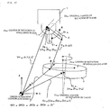
  • FIG. 2 is a diagram illustrating the calculation of the position of a machine having this misalignment.
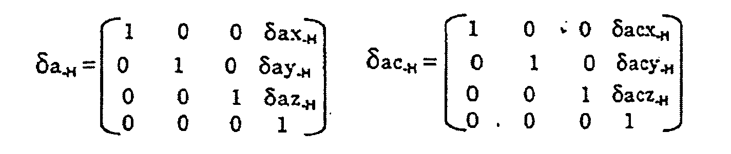
  • This misalignment is represented by the component ⁇ ac -H ( ⁇ acx -H , ⁇ acy -H , ⁇ acz -H ) of the X-, Y-, and Z-axes of the distance of divergence from the actual center of rotation of the A-axis Aa -H to the actual center of rotation of the C-axis Ac -H , and the rotational misalignment ( ⁇ c -H , ⁇ bc -H , ⁇ c -H ) of the center of rotation of the C-axis about these X-, Y-, and Z-axes of rotation.
  • ⁇ ac -H ( ⁇ acx -H , ⁇ acy -H , ⁇ acz -H ) is the vector from the actual center of rotation of the A-axis to the actual center of rotation of the C-axis.
  • ( ⁇ c -H , ⁇ c -H , ⁇ c -H ) represents the misalignment whereby the actual center of rotation of the C-axis Ac -H is inclined by rotating ⁇ c -H about the X-axis, ⁇ c -H about the Y-axis and ⁇ c -H about the Z-axis from the original center of rotation of the C-axis Cc -H .
  • This misalignment is represented by the misalignment ⁇ a -H ( ⁇ ax -H , ⁇ ay -H , ⁇ az -H ) of the X-, Y-, and Z-axes in the linear axis direction and by the rotational misalignment ( ⁇ a -H , ⁇ a -H , ⁇ a -H ) of the center of rotation of the A-axis about the X-, Y-, Z-axes.
  • ⁇ a -H ( ⁇ ax -H , ⁇ ay -H , ⁇ az -H ) represents the components of the distance of divergence in the direction of the X-, Y-, and Z-axes from the original center of rotation of the A-axis Ca -H to the actual center of rotation of the A-axis Aa -H (the vector from the intersection between the original center of rotation of the C-axis Cc -H and the original center of rotation of the A-axis Ca -H to the actual center of rotation of the A-axis).
  • ( ⁇ a -H , ⁇ a -H , ⁇ a -H ) represents the error whereby the actual center of rotation of the A-axis Aa -H is inclined by rotating ⁇ a -H about the X-axis, ⁇ a -H about the Y-axis and ⁇ a -H about the Z-axis from the original center of rotation of the A-axis Ca -H .
  • This misalignment is represented by the misalignment ⁇ s -H ( ⁇ sx -H , ⁇ sy -H , ⁇ sz -H ) in the linear axis direction of the X-, Y-, and Z-axes and the rotational misalignment ⁇ s -H ( ⁇ s -H , ⁇ s -H , gs -H ) of the turning center of the spindle about these axes.
  • ⁇ s -H ( ⁇ s -H , ⁇ s -H , ⁇ s -H ) represents the error whereby the actual turning center of the spindle As -H is inclined by rotating ⁇ s -H about the X-axis, ⁇ s -H about the Y-axis and ⁇ s -H about the Z-axis from the original turning center of the spindle Cs -H .
  • FIG. 2 is an illustrative diagram in which these misalignments are taken into consideration to compute the machine position
  • FIG. 3 is an illustrative diagram in which only the misalignment is shown.
  • FIGS. 4 to 6 are diagrams illustrating the basic principles of taking these misalignments into consideration to compute the machine position.
  • FIG. 4 shows a situation in which the rotational angle of the axes of rotation A and C are "0."
  • the vector shown by the broken line represents the actual tool length vector V1 from the tip of the tool to the intersection P1 between the original center of rotation of the C-axis Cc -H and the original center of rotation of the A-axis Ca -H in the direction of the original turning center of the spindle Cs -H .
  • This vector becomes V2 by way of the incline error ⁇ s -H ( ⁇ s -H , ⁇ s -H , ⁇ s -H ) of the spindle.
  • This vector becomes V3 by way of error ⁇ s -H ( ⁇ sx -H , ⁇ sy -H , ⁇ sz -H ) in the linear axis direction of the spindle. That is to say, the vector V3 represents the actual tool length vector of the tool length h from the tip of the tool due to the misalignment of the spindle when the rotational angles of the axes of rotation A and C are "0.”
  • This actual tool length vector V3 changes to the vector of V5 shown in FIG. 5 by way of the rotation instruction a for the A-axis and the misalignment of the actual center of rotation of the A-axis Aa -H with respect to the original center of rotation of the A-axis Ca -H .
  • the actual tool length vector V3 computed in FIG. 4 changes to vector V4 due to the rotational misalignment ( ⁇ a -H , ⁇ a -H , ⁇ a -H ) about the X-, Y-, Z-axes and the misalignment ⁇ a -H ( ⁇ ax -H , ⁇ ay -H , ⁇ az -H ) of the A-axis in the direction of the X-, Y-, and Z-axes; and the actual center of rotation of the A-axis becomes P2.
  • the actual tool length vector after this rotation becomes V5.
  • This actual tool length vector V5 becomes vector V7 shown in FIG. 6 by way of the rotation instruction c for the C-axis and the misalignment of the actual C-axis center Ac -H with respect to the original C-axis center Cc -H .
  • the center of rotation of the C-axis moves to point P3 of FIG.
  • the actual tool length vector V5 changes to the vector V6 due to the misalignment of the C-axis, that is to say, due to the components ⁇ ac -H ( ⁇ acx -H , ⁇ acy -H , ⁇ acz -H ) of the distance of divergence in the direction of the X-, Y-, and Z-axes from the actual center of rotation of the A-axis Aa -H to the actual center of rotation of the C-axis Ac -H , and the rotational misalignment ( ⁇ c -H , ⁇ c -H , ⁇ c -H ) about these X-, Y-, and Z-axes.
  • ⁇ ac -H ⁇ acx -H , ⁇ acy -H , ⁇ acz -H
  • the actual tool length vector is brought to V7 by rotating the tool by an equivalent of the rotation instruction c for the C-axis about point P3.
  • This point P3 becomes the machine position where there is misalignment.
  • the machine position is computed by adding the actual tool length vector V7 at the time when misalignment is corrected and the positional instructions R (a, c) to the A- and C-axes of rotation are executed for the positional instructions P (x, y, z) (refer to FIG. 2).
  • Vm -H' Mwo -H * Mp -H * Mc -H' * ⁇ ac -H * Ma -H' * ⁇ a -H * ⁇ s -H * ⁇ s -H * Vt -H
  • the tool length vector Vt -H (0, 0, h, 1) T that is initially set is multiplied by the transformation matrices of the rotational error ⁇ s -H for the X-, Y-, and Z-axes of the spindle and the X, Y, Z components ds -H of the spindle misalignment to compute the actual tool length vector V3 shown in FIG. 4.
  • the computed vector V3 is multiplied by the misalignment ⁇ a -H in the X-, Y-, and Z-axes direction of the A-axis and the transformation matrix Ma -H ' that includes the rotation instruction a for the A-axis and the rotational misalignment ( ⁇ a -H , ⁇ a -H , ⁇ a -H ) about the X-, Y-, and Z-axes to compute the actual tool length vector V5 shown in FIG. 5.
  • the computed vector V5 is multiplied by the transformation matrix of the components ⁇ ac -H of the divergence distance in the direction of the X-,Y-, and Z-axes from the actual center of rotation of the A-axis Aa -H to the actual center of rotation of the C-axis Ac -H , and the transformation matrix Mc -H' that includes the rotation instruction c for the C-axis and the rotational misalignment ( ⁇ c -H , ⁇ c -H , ⁇ c -H ) about the X-, Y-, and Z-axes of the C-axis to compute the actual tool length vector V7 shown in FIG. 6.
  • the machine position Vm -H' in the instruction position for which the misalignment has been corrected is computed by multiplying the computed vector V7 by the matrix Mp -H whereby the vector of the positional instructions P (x, y, z) from the origin in the workpiece coordinate system is added, and by the matrix Mwo -H whereby the machine origin and the workpiece origin offset vector are added, as shown in FIG. 2.
  • the second embodiment of the present invention is an example of a machine in which a table to which a workpiece is mounted rotates on two axes of rotation.
  • the machine has an A-axis (rotating about the X-axis) and a C-axis (rotating about the Z-axis), as axes of rotation, as well as the orthogonal axes of linear motion X, Y, and Z.
  • the A-axis serves as a master axis; the C-axis operates on the A-axis; and the center of rotation of the A-axis Ca -T and the center of rotation of the C-axis Cc -T intersect, as shown in FIG. 7.
  • the tool direction is the Z-axis direction.
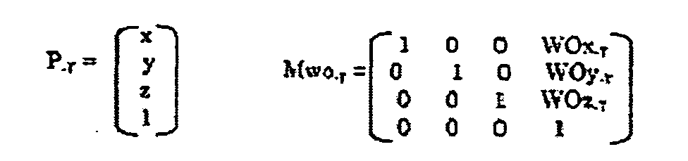
  • Vm -T Mvt -T * Mad -T * Mcd -T * Mwo -T * P -T
  • the instruction position for a case in which there is no rotation about the axes of rotation A and C is computed by multiplying the vector P -T of the instructed position P (x, y, z) in the table coordinate system (workpiece coordinate system) by the matrix Mwo -T whereby the workpiece origin offset vector from the origin of the machine coordinate system to the origin of the table coordinate system (workpiece coordinate system) is added, as shown in FIG. 7.
  • the transformation matrix Mcd -T whereby the tool is caused to rotate about the C-axis by an equivalent of the instruction position c
  • the instruction position for a case in which a rotation is made about the C-axis by an equivalent of instruction c is computed.
  • the misalignment of the actual center of rotation of the C-axis Ac -T with respect to the original center of rotation of the C-axis (reference position) Cc -T is represented by misalignment ⁇ c -T ( ⁇ cx -T , ⁇ cy -T , ⁇ cz -T ) in the X-, Y-, and Z-axes of linear motion, and the rotational misalignment ( ⁇ c -T , ⁇ c -T , ⁇ c -T ) about these X-, Y-, and Z-axes.
  • ⁇ c -T ( ⁇ cx -T , ⁇ cy -T , ⁇ cz -T ) is represented by the X, Y, and Z components of the divergence distance from the actual center of rotation of the C-axis Ac -T to the actual center of rotation of the A-axis Cc -T .
  • this misalignment is represented as a vector to the actual center of rotation of the C-axis from the intersection between the original center of rotation of the C-axis Cc -T and the original center of rotation of the A-axis Ca -T .
  • ( ⁇ c -T , ⁇ c -T , ⁇ c -T ) represents the misalignment whereby the actual center of rotation of the C-axis Ac -T is inclined by rotating ⁇ c -T about the X-axis, ⁇ c -T about the Y-axis and ⁇ c -T about the Z-axis from the original center of rotation of the C-axis Cc -T .
  • the misalignment of the actual center of rotation of the A-axis Aa -T with respect to the original center of rotation of the A-axis (reference position) Ca -T is represented as follows. ⁇ a -T ( ⁇ ax -T , ⁇ ay -T , ⁇ az -T ) This misalignment is represented by the X, Y, and Z components of the distance of divergence from the original center of rotation of the A-axis Ca -T to the actual center of rotation of the A-axis Aa -T .
  • this misalignment is represented as a vector to the actual center of rotation of the A-axis from the intersection between the original center of rotation of the C-axis Cc -T and the original center of rotation of the A-axis Ca -T .
  • ( ⁇ a -T , ⁇ a -T , ⁇ a -T ) represents the misalignment whereby the actual center of rotation of the A-axis Aa -T is inclined by rotating ⁇ a -T about the X-axis, ⁇ a -T about the Y-axis and ⁇ a -T about the Z-axis from the original center of rotation of the A-axis Ca -T .
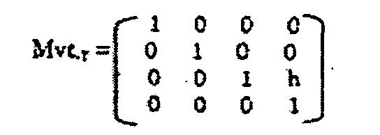
  • the vector P -T of the instruction position P (x, y, z), the transformation matrix Mwo -T of the workpiece origin offset WO -T (WOx -T, WOy -T, WOz -T, 1) T , the matrix Mvt -T of the tool length vector Vt -T (0, 0, h, 1) T are as described above.
  • the vector P -T of the instruction position P (x, y, z) in the table coordinate system is multiplied by the matrix Mwo -T whereby the vector of the workpiece origin offset WO -T is added so that the instruction position in the machine coordinate system is computed, as shown in FIG. 8.
  • the computed instruction position is multiplied by the transformation matrix Mcd -T ' that includes the misalignment ⁇ c -T ( ⁇ cx -T, ⁇ cy -T, ⁇ cz -T ) of the C-axis in the direction of the X-, Y-, and Z-axes and the rotational misalignment ( ⁇ c -T, ⁇ c -T , ⁇ c -T ) of the C-axis about these X-, Y-, and Z-axes and the instruction c to the C-axis so that the misalignment of the C-axis is corrected, and the position resulting from the rotation of the C-axis by an equivalent of instruction c is computed.
  • this computed position is multiplied by the transformation matrix Mad -T ' that includes the misalignment ⁇ a -T ( ⁇ ax -T , ⁇ ay -T , ⁇ az -T ) of the A-axis in the direction of the X-, Y-, and Z-axes; the rotational misalignment ( ⁇ a -T , ⁇ a -T , ⁇ a -T ) of the A-axis about these X-, Y-, and Z-axes and the instruction a to the A-axis so that the misalignment of the A-axis is corrected, and the position resulting from the rotation of the A-axis by an equivalent of instruction a is computed.
  • This computed position is multiplied by the matrix Mvt -T of the tool length vector Vt -T (0, 0, h, 1) T to compute the machine position Vm -T' .
  • the third embodiment of the present invention is an example of a machine in which the table 3 is rotated about a rotating axis (C-axis), the tool head 1 is rotated about another rotating axis (B-axis), the C-axis rotates about the Z-axis, and the B-axis rotates about the Y-axis.
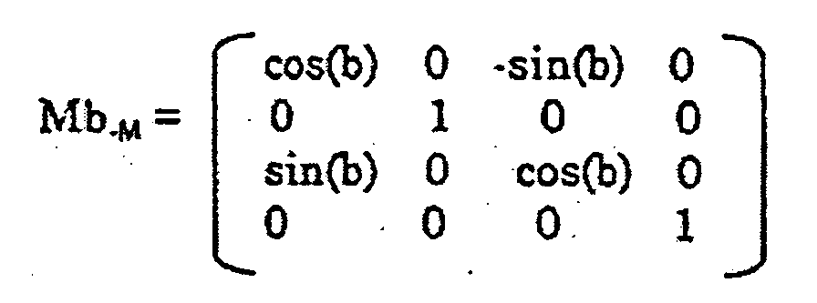
  • the vector P -M that shows the positional instruction values P (x, y, z) in the table coordinate system is multiplied by the matrix Mwo -M whereby the vector of the workpiece origin offset WO -M (WOx -M , WOy -M , WOz -M , 1) T is added, and then the result is multiplied by the rotation transformation matrix Mcd -M of the rotation instruction c for the C-axis to compute the instruction position Vp -M after the C-axis has been rotated by an equivalent of instruction c (Eq. (5)), as shown in FIG. 9.
  • the tool length vector Vt -M rotation is multiplied by the transformation matrix Mb -M whereby the B-axis is allowed to rotate by an equivalent of instruction b to compute the tool length vector Vt -M in which the B-axis has been rotated by an equivalent of instruction b (Eq. (6)).
  • the machine position Vm -M is determined by adding the tool length vector Vv -M in which the B-axis has been allowed to rotate by an equivalent of instruction b to the instruction position Vp -M after the C-axis has been rotated by an equivalent of instruction c , as shown in Eq. (7).
  • the misalignment of the actual center of rotation of the C-axis Ac -M with respect to the original center of rotation of the C-axis (reference position) Cc -M is represented by the misalignment ⁇ c -M ( ⁇ cx -M , ⁇ cy -M , ⁇ cz -M ) in the direction of the X-, Y-, and Z-axes of linear motion, and the rotational misalignment ( ⁇ c -M , ⁇ c -M , ⁇ c -M ) about these X-, Y-, and Z-axes.
  • ⁇ c -M ( ⁇ cx -M , ⁇ cy -M , ⁇ cz -M ) are the X, Y, and Z components of the divergence distance from the actual center of rotation of the C-axis Ac -M to the original center of rotation of the C-axis Cc -M .
  • ( ⁇ c -M , ⁇ c -M , ⁇ c -M ) represents the misalignment whereby the actual center of rotation of the C-axis Ac -M is inclined by rotating ⁇ c -M about the X-axis, ⁇ c -M about the Y-axis and ⁇ c -M about the Z-axis from the original center of rotation of the C-axis Cc -M .
  • the misalignment of the actual center of rotation of the B-axis Ab -M with respect to the original center of rotation of the B-axis (reference position) Cb -M is represented as follows. ⁇ b -M ( ⁇ bx -M , ⁇ by -M , ⁇ bz -M ) This misalignment is represented by the X, Y, and Z components of the distance of divergence from the original center of rotation of the B-axis Cb -M to the actual center of rotation of the B-axis Ab -M .
  • ( ⁇ b -M , ⁇ b -M , ⁇ b -M ) represents the fact that the actual center of rotation of the B-axis Ab -M is rotated ⁇ b -M about the X-axis, ⁇ b -M about the Y-axis, and ⁇ b -M about the Z-axis, and is inclined from the original center of rotation of the B-axis Cb -M .
  • the machine position for a machine which has misalignment in the third embodiment is given by the following equations (Eq. (8) to Eq. (10)), in association with Eq. (5) to Eq. (7) which determines the position of a machine which has no misalignment, as described above.
  • Vp -M ' Mcd -M ' * Mwo -M * P -M
  • the vector P -M that shows the positional instruction values P (x, y, z) in the table coordinate system is multiplied by the matrix Mwo -M whereby the vector of the workpiece origin offset WO -M (WOx -M , WOy -M , WOz -M , 1) T is added to compute the instruction position in the machine coordinate system, as shown in FIG. 10.
  • This computed instruction position is then multiplied by the transformation matrix Mcd -M' that includes the instruction c for the C-axis, the rotation misalignment ⁇ c -M ( ⁇ cx -M , ⁇ cy -M , ⁇ cz -M ) of the C-axis in the direction of the X-, Y-, and Z-axes, and the rotational misalignment ( ⁇ c -M , ⁇ c -M , ⁇ c -M ) of the C-axis about these X-, Y-, and Z-axes so that the misalignment of the C-axis is corrected and the instruction position Vp -M in which the C-axis has been rotated by an equivalent of instruction c is computed (Eq. (8)).
  • the tool length vector Vt -M is multiplied by the matrix ⁇ b -M whereby the vector of the misalignment of the X, Y, and Z components of the B-axis is added so that the rotational misalignment of the B-axis is corrected, and the result is multiplied by the transformation matrix Mb -M ' whereby the B-axis is rotated by an equivalent of instruction b so that the rotational misalignment of the B-axis is corrected, and the tool length vector Vv -M ' in which the B-axis has been rotated by an equivalent of instruction b is computed (Eq. (9)).
  • the machine position V m-M ' is determined by adding the tool length vector Vv -M ' in which the B-axis has been rotated by an equivalent of instruction b to the instruction position Vp -M ' after the C-axis has been rotated by an equivalent of instruction c , as shown in Eq. (10).
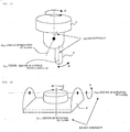
  • the present invention may also be applied to cases in which the turning center of the spindle is structurally not at the center of rotation of the axis of rotation on which the spindle is set, namely, to cases in which the turning center of the spindle Cs -H does not intersect with the center of rotation of the A-axis Ca -H , as shown in FIG. 11, or to the cases in which the center of rotation of the C-axis Cc -T and the center of rotation of the A-axis Ca -T do not intersect in machines in which a table rotates, as shown in FIG. 12.
  • the axes of rotation were assumed to be orthogonal in the case of a tool head rotary machine and in the case of a table rotary machine, but application may also be made to cases in which the axes of rotation are not orthogonal.
  • the structure of the axes of rotation in the above-described embodiments assumed the use of the C- and A-axes in the case of a tool head rotary machine, the A- and C-axes in the case of a table rotary machine, and the C- and B-axes in the case of a machine in which both the tool head and the table rotated, but application may also be made to machines with other axial structures; and application may also be naturally made to machines provided with only a single axis of rotation.
  • FIG. 13 is a block diagram of a numerical control device that implements the methods in the embodiments for correcting the above-described misalignment and computing the machine position.
  • CPU 11 is a processor for the comprehensive control of a numerical control device 100.
  • CPU 11 reads a system program stored in ROM 12 by way of a bus 20, and controls the entire numerical control device in accordance with the system program.
  • Temporary calculation data, display data, and various data inputted by an operator by way of a display/MDI unit 70 are stored in RAM 13.
  • a CMOS memory 14 is backed up with a battery (not depicted), and is structured as nonvolatile memory in which the storage condition is maintained even if the power supply for the numerical control device 100 is switched off.
  • a work program read by way of an interface 15, a work program inputted by way of the display/MDI unit 70, and the like are stored in the CMOS memory 14.
  • Software for performing calculations in accordance with Eqs. (1) to (10), which are used to implement the misalignment correction of the present invention, is also stored in the ROM 12.
  • Interface 15 is one with which it is possible to connect the numerical control device 100 with an adapter or other external equipment 72.
  • Work programs and other data are read from external equipment 71.
  • the work program compiled in the numerical control device 100 is capable of being stored in external storage means by way of the external equipment 72.
  • PMC (programmable machine control device) 16 outputs signals to and controls an auxiliary device (an actuator such as a robot hand for tool replacement, for example) for a machine tool by way of an I/O unit 17 with the aid of a stored sequence program. PMC may sometimes be provided to the machine. Signals are received from switches and other devices on the control panel that is disposed on the main unit of the machine tool, any required signal processing is performed, and the data is thereafter delivered to CPU 11.
  • the display/MDI unit 70 is a manual data input device equipped with a display, a keyboard, and the like; and an interface 18 receives instructions and data from the keyboard of the CRT/MDI unit 70 and delivers these to CPU 11.
  • Axial control circuits 30 to 33 for the axes receive movement instruction values for the individual axes from CPU 11 and then output instructions for the axes to servo amplifiers 40 to 43.
  • the servo amplifiers 40 to 43 receive the instructions and drive servomotors 50 to 53 for each axis (the X-, Y-, and Z-axes of linear motion, and the axes of rotation).
  • the servomotors 50 to 53 for the axes include position and velocity detectors, the position and velocity feedback signals from the position and velocity detectors are fed back to the axial control circuits 30 to 33, and feedback control of the position and velocity is performed.
  • the position and velocity feedback is omitted in FIG. 13.
  • a spindle control circuit 60 receives turning instructions for the spindle, and outputs a spindle velocity signal to a spindle amplifier 61.
  • the spindle amplifier 61 receives the spindle velocity signal and causes a spindle motor 62 to rotate at the instructed rotational velocity.
  • a position coder 63 provides a feedback pulse as feedback to the spindle control circuit 60 to control the velocity in synchronism with the rotation of the spindle motor 62.
  • the structure of the above-described numerical control device does not differ from the structure of a conventional numerical control device.
  • functions not included in a conventional numerical control device have been added such that software for correcting the misalignment of a machine and outputting instruction positions is stored in storage means; the misalignment of divergence and incline of the center of an axis of rotation from the original position is corrected, the misalignment represented by the divergence and incline of the turning center of the spindle from the original position is corrected, movement instructions are outputted to the machine, as described above.
  • ⁇ ac -H ( ⁇ acx -H , ⁇ acy -H , ⁇ acz -H ) and ( ⁇ c -H , ⁇ c -H , ⁇ c -H ) are set as the misalignment of the C-axis, ⁇ a -H ( ⁇ ax -H , ⁇ ay -H , ⁇ az -H ) and ( ⁇ a -H , ⁇ a -H , ⁇ a -H , ⁇ a -H ) as the misalignment of the A-axis, and ⁇ s -H ( ⁇ sx -H , ⁇ sy -H , ⁇ sz -
  • ⁇ c -T ( ⁇ cx -T , ⁇ cy -T , ⁇ cz -T ) and ( ⁇ c -T , ⁇ c -T , ⁇ c -T ) are set as the misalignment of the C-axis
  • ⁇ a -T ( ⁇ ax -T , ⁇ ay -T , ⁇ az -T ) and ( ⁇ a -T , ⁇ a -T , ⁇ a -T ) as the misalignment of the A-axis.
  • ⁇ c -M ( ⁇ cx -M , ⁇ cy -M , ⁇ cz -M ) and ( ⁇ c -M , ⁇ c -M , ⁇ c -M ) are set as the misalignment of the C-axis, and ⁇ b -M ( ⁇ bx -M , ⁇ by -M , ⁇ bz -M ) and ( ⁇ b -M , ⁇ b -M , ⁇ b -M ) as the misalignment of the B-axis.
  • misalignment amounts may be set as parameters provided to the CMOS memory 14 or other means in the numerical control device 100.
  • the error amounts of these may be stored in the machine in advance, and when the machine is connected to the numerical control device 100 the misalignment amount is transmitted from a PLC (programmable logic control device) provided to the machine, and the transmitted misalignment amount is set.
  • the misalignment amount may be received by communication from an external computer by way of the interface 15 or other means, and may then be set.
  • the type of machine to be connected in other words, a tool head rotary machine, a table rotary machine, a tool head and table rotary machine, or other type of machine may be set in the numerical control device 100.
  • Other parameters that are set include the tool length, the workpiece origin (workpiece origin offset), the intersection between the center of rotation of the A-axis and the center of rotation of the C-axis in the case of a table rotary machine, and the position of the center of rotation of the C-axis in the case of a tool head and table rotary machine.
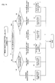
  • FIG. 14 is a processing flowchart for tool length correction executed by the numerical control device 100.
  • CPU 11 determines whether or not the misalignment amount is set (step 1); if the misalignment amount is not set, the machine structure (type) that has been set is determined (step 2); and if the machine is a tool head rotary machine, then processing for Eq. (1) is selected (step 3) and the calculation of Eq. (1) is thereafter performed for the positional instruction generated by the program to process the tool length correction.
  • processing for Eq. (3) is selected (step 4), and if the machine is one in which a tool head and a table rotate, then processing for Eqs. (5) to (7) is selected (step 5) and the selected processing is thereafter performed for the positional instruction generated by the program to process the tool length correction.
  • the machine structure (type) is determined (step 6); if the machine is a tool head rotary machine, then processing for Eq. (2) is selected (step 7); if the machine is a table rotary machine, then processing for Eq. (4) is selected (step 8); if the machine is one in which a tool head and a table rote, then processing for Eqs. (8) to (10) is selected (step 9); and the selected processing is thereafter performed for the positional instruction generated by the program to process the tool length correction.
  • the present invention is capable of high precision work control because even if there is misalignment in the axis of rotation or the turning center of the spindle, the machine position in which the misalignment has been corrected is instructed.

Landscapes

  • Engineering & Computer Science (AREA)
  • Human Computer Interaction (AREA)
  • Manufacturing & Machinery (AREA)
  • Physics & Mathematics (AREA)
  • General Physics & Mathematics (AREA)
  • Automation & Control Theory (AREA)
  • Numerical Control (AREA)

Abstract

A machine has a tool head which rotates on a C-axis (about the Z-axis) and an A-axis (about the X-axis). A tool length vector is multiplied by a matrix whereby a misalignment component δs-H and the incline error (αs-H, βs-H, γs-H) of a spindle are corrected so that the tool length vector due to the misalignment of the spindle is obtained. The vector thus obtained is further multiplied by a transformation matrix that includes a rotation instruction a for the A-axis and misalignments of the A-axis δa-H (αa-H, βa-H, γa-H) to correct the misalignment of the A-axis so that the tool length vector as found when the A-axis has rotated by an equivalent of instruction a is determined. The vector thus determined is further multiplied by a transformation matrix that includes a rotation instruction c for the C-axis and misalignments of the C-axis δac-H (αc-H, βc-H, γc-H) to correct the misalignment of the C-axis, so that a tool length vector as found when the C-axis has rotated by an equivalent of instruction c is determined. The tool length vector thus determined is added to the vector of positional instruction values (x, y, z) and a workpiece origin offset vector MWO-H , so that the machine position Vm-H' is obtained.

Description

    BACKGROUND OF THE INVENTION 1. Field of the Invention
  • The present invention relates to a numerical control device for controlling a machine having an axis of rotation other than an axis of linear motion, and a numerical control method thereof.
  • 2. Description of the Related Art
  • Machines having an axis of rotation other than an axis of linear motion are used as machine tools that work the free form surfaces of molds and the like. Five-axis machine tools equipped with two rotating axes and linearly moving axes X, Y, and Z are known. Because such machines are equipped with rotating axes, tools can be tilted to work in any direction with respect to the work surface of the workpiece in association with the rotation of these rotating axes. Because the amount of compensation to the tool length changes due to the tilting of the tool, work is performed while compensating for the tool length (Refer to Japanese Patent Application Laid-open Nos. H3-109606 and H5-100723, for example).
  • Known is an invention (Japanese Patent Application Laid-open No. 2001-269839) for corrects the spindle head error in a five-axis machine tool equipped with members that rotate about the linearly moving axes X, Y, and Z, with a C-axis, which is the axis of rotation about the vertical axis line, and with a B'-axis inclined at a prescribed angle with respect to the C-axis, by fixing the B'-axis at a prescribed angle; measuring the spindle end position for each prescribed swivel angle when rotating a member about the C-axis; performing a multiple regression analysis with a regression equation and computing the swivel plane from this measurement data; computing the axial vector of the C-axis member; fixing the C-axis at a prescribed angle; measuring the spindle end position at every prescribed swivel angle when swiveling a member about the B-axis; performing a multiple regression analysis with a regression equation, computing the swivel plane from this measurement data, and computing the axial vector of the B-axis member; computing the spindle end position in a state in which the members swivel about the axis lines of these axial vectors; taking the difference between this spindle end position and the precise spindle position as the spindle head position error; inverting the sign of the spindle head position error and using the result as the correction value; and offsetting the coordinate system of an NC program in order to correct the tilt error from the vertical axis line of the C-axis, the incline angle error of the B'-axis, and the error in the position of the center of rotation of the B'- and C-axes.
  • The tool length correction methods cited in the above-mentioned Japanese Patent Application Laid-open Nos. H3-109606 and H5-100723 do not take the incline and misalignment of the center of an axis of rotation into consideration. Cases in which the center of an axis of rotation diverges or becomes inclined from the original position (cases in which the control system for executing a work program has an error between the recognized center axis of rotation and the direction thereof, and the actual center axis of rotation and the direction thereof) are not taken into consideration. Also not taken into consideration is the case in which the center of swiveling about the main axis diverges or becomes inclined from the original position.
  • However, it is difficult to accurately manufacture the center of an axis of rotation in the original position and direction, and the turning center of the spindle in the original position and direction because of factors related to the manufacture of machine tools, and errors occur. In the above-described Japanese Patent Application Laid-open No. 2001-269839, the center position error of the axis of rotation and the tilt error are taken into consideration, and the error of the spindle head position is corrected, but with this method, one of two axes of rotation is fixed, a multiple regression analysis is performed with a regression equation on the basis of the data obtained from measuring the spindle end position for each position in which the other axis is rotated at a prescribed angle, the swivel plane is computed, the axial vector is computed, the spindle end position is computed in a state in which these axial vectors are swiveled; the difference with the original spindle position is taken to be the spindle head position error; and the NC coordinate system is offset in accordance with the spindle head position error, resulting in complicated processing.
  • The method cited in the Japanese Patent Application Laid-open No. 2001-269839 has the following drawbacks.
  • For each positioning of the two axes of rotation, these axes are swiveled a prescribed angle and measured each time, and the actual direction vectors of the axes of rotation thereof are computed. Therefore, this approach is disadvantageous in that time is required for measurement each time the axes of rotation are positioned, and that the invention cannot be used in continuous working that includes movement of the axes of rotation. Assuming that the centers of rotation of the two axes of rotation intersect with each other, no consideration is given to the case when there is divergence between the two centers of rotation. Another drawback is that no consideration is given to the error between the center of rotation of the spindle and the axis of rotation.
  • SUMMARY OF THE INVENTION
  • The numerical control device according to the present invention relates to a numerical control device for controlling a machine having an axis of linear motion and at least one axis of rotation on a tool head or a table. This numerical control device has means for obtaining a machine position to which a machine should actually move so that the relation between a workpiece and a tool as found when there is no mechanical error is maintained on the basis of a reference position at which there is no mechanical error in the axis of rotation and an amount of misalignment of an actual axis of rotation from the reference position, and/or on the basis of a reference position at which there is no mechanical error in the turning center of the spindle and an amount of misalignment of an actual turning center of the spindle from the reference position of the turning center of the spindle; and drive control means for driving the axis of rotation and the axis of linear motion to the machine position obtained by the machine position obtaining means.
  • This numerical control device may take the following embodiments.
  • The machine is one in which the tool head rotates about at least one axis, one in which the table rotates about at least one axis, or one in which the tool head and the table rotate.
  • The amount of misalignment is set by a parameter in the numerical control device.
  • The amount of misalignment is delivered to the numerical control device by a signal from the machine to the numerical control device, or is reported to the numerical control device by a signal from external equipment to the numerical control device.
  • The numerical control method according to the present invention relates to a numerical control method that uses a numerical control device for a machine having an axis of linear motion and at least one axis of rotation on a tool head or a table. This numerical control method has a step of obtaining a machine position to which a machine should actually move so that the relation between a workpiece and a tool as found when there is no mechanical error is maintained on the basis of a reference position at which there is no mechanical error in the axis of rotation and an amount of misalignment of an actual axis of rotation from the reference position, and/or on the basis of a reference position at which there is no mechanical error in the turning center of the spindle and an amount of misalignment of an actual turning center of the spindle from the reference position of the turning center of the spindle; and a step of moving the axis of linear motion and the axis of rotation to the machine position thus obtained.
  • This numerical control method may take the following embodiments.
  • The machine is one in which a tool head rotates about at least one axis, and the method has a step of correcting the tool length vector on the basis of a reference position at which there is no mechanical error in the axis of rotation and an amount of misalignment of an actual axis of rotation from the reference position, and/or a reference position at which there is no mechanical error in the turning center of the spindle, an amount of misalignment of an actual turning center of the spindle from the reference position of the turning center of the spindle, and instruction for the axis of rotation; and a step of adding the instruction position vector to the corrected tool length vector to obtain the machine position.
  • The machine is one in which a table rotates about at least one axis, and the method has a step of adding an offset of the origin of a table coordinate system to an instruction position value in the table coordinate system and computing the instruction position in the machine coordinate system; and a step of correcting the misalignment of the instruction position in the machine coordinate system on the basis of a reference position at which there is no mechanical error in the axis of rotation, an amount of misalignment of the actual axis of rotation from the reference position, and the instruction position for the axis of rotation, obtaining a rotation position to which the axis of rotation has rotated according to the instruction, and adding the tool length vector to the position to obtain the machine position.
  • The machine is one in which a tool head and a table rotate, and the method has a step of adding an offset of the origin of a table coordinate system to a position instruction in the table coordinate system and obtaining an instruction position in the machine coordinate system; a step of obtaining an instruction position for which the misalignment has been corrected on the basis of an amount of misalignment of the actual axis of rotation provided to the table from a reference position at which there is no mechanical error in the axis of rotation and an instruction position for the axis of rotation; a step of obtaining an attitude of the tool for which misalignment has been corrected on the basis of an amount of misalignment of the actual axis of rotation provided to the tool head from a reference position at which there is no mechanical error in the axis of rotation and the instruction position of the axis of rotation, in addition to a tool vector; and a step of obtaining a machine position on the basis of an instruction position for which the misalignment has been corrected and an attitude of the tool for which the misalignment has been corrected.
  • The amount of misalignment is delivered to the numerical control device by a parameter setting in the numerical control device, a signal from the machine, or a signal from external equipment.
  • According to the present invention, there is provided a numerical control device and a numerical control method that are simple, are capable of high precision working, and can perform continuous working that includes movement of an axis of rotation, even when the center of an axis of rotation diverges or is inclined from the original position, or when the turning center of the spindle diverges or is inclined from the original position in a numerical control device for controlling a machine that includes the axis of rotation.
  • BRIEF DESCRIPTION OF THE DRAWINGS
  • FIG. 1 is a diagram illustrating the calculation of a machine position in a machine having axes of rotation A and C when there is no misalignment.
  • FIG. 2 is a diagram illustrating the calculation of the machine position when the machine in FIG. 1 has misalignment.
  • FIG. 3 is an enlarged diagram illustrating the misaligned portion of the machine in FIG. 1.
  • FIG. 4 is a diagram illustrating the change in the tool length vector due to misalignment of the turning center of the spindle in the machine in FIG. 1.
  • FIG. 5 is a diagram illustrating the change in the tool length vector due to misalignment of the center of rotation of the A-axis and to instruction for the A-axis in the machine in FIG. 1.
  • FIG. 6 is a diagram illustrating the change in the tool length vector due to misalignment of the center of rotation of the C-axis and to instruction for the C-axis in the machine in FIG. 1.
  • FIG. 7 is a diagram illustrating the manner in which the machine position is computed where there is no misalignment, in a machine having axes of rotation A and C on a table.
  • FIG. 8 is a diagram illustrating the manner in which the machine position is computed when there is misalignment, in a machine having axes of rotation A and C on a table.
  • FIG. 9 is a diagram illustrating the manner in which the machine position is computed when there is no misalignment, in a machine having an axis of rotation on a tool head and a table.
  • FIG. 10 is a diagram illustrating the manner in which the machine position is computed when there is misalignment, in a machine having an axis of rotation on a tool head and a table.
  • FIG. 11 is a diagram illustrating a machine in which the turning center of the spindle to which the present invention is applicable does not intersect with the center of rotation of the A-axis.
  • FIG. 12 is a diagram illustrating a machine in which center of rotation of the C-axis and the center of rotation of the A-axis do not intersect in a machine with a rotating table to which the present invention is applicable.
  • FIG. 13 is a partial block diagram of an embodiment of a numerical control device for correcting the misalignment and the tool length of a machine.
  • FIG. 14 is a processing flowchart for tool length correction in which an embodiment of the numerical control device in FIG. 13 is implemented.
  • DESCRIPTION OF THE PREFERRED EMBODIMENTS
  • Machines (machine tools) that have axes of rotation exist in multiple types (structural differences). The embodiments in which the present invention is adapted to each type of machine are demonstrated with applications to three types of machines, namely, tool head rotary machines, table rotary machines, and tool head and table rotary machines, and the basic principles of the present invention comprising these three embodiments are described below.
  • 1. Embodiment 1 of the present invention (tool head rotary machines)
  • The first embodiment of the present invention is a tool head rotary machine having orthogonal axes of linear motion X, Y, and Z; the tool head is provided with an A-axis (rotating about the X-axis) and a C-axis (rotating bout the Z-axis) as axes of rotation; the C-axis is the master axis; the A-axis operates on the C-axis; and the tool direction is the Z-axis direction when the angle of the A- and C-axes is "0."
  • The tool length vector Vt-H (0, 0, h, 1)T and the workpiece origin offset WO-H (WOx-H, WOy-H, WOz-H, 1)T when the angle of rotation of the A-axis and the C-axis is "0" are given as the initial conditions. The symbol "T" in a homogeneous coordinate system hereinafter refers to transposition.
  • (1-1) Method for computing the machine position when there is no misalignment
  • Following is a description of a misalignment-free case in which the center of an axis of rotation and the turning center of the spindle have no tilt or position misalignment, and have no divergence or inclination from the original position, that is to say, a case in which the actual position and direction are aligned with the position and direction of the center of the axis of rotation or the turning center of the spindle recognized by the work program and the control system.
  • FIG. 1 is a diagram illustrating the calculation of a machine position in a machine having axes of rotation A and C when there is no misalignment. Reference numerals 1 and 2 denote a tool head and a tool.
  • When the positional instruction values P (x, y, z) are given to the X-, Y-, and Z-axes of linear motion, and the positional instructions R (a, c) to the A- and C-axes of rotation, the machine position Vm-H (X, Y, Z, 1)T is computed according to the following Eq. (1). Vm-H = Mwo-H * Mp-H * Mc-H * Ma-H * Vt-H
  • In the expression, Mwo-H, Mp-H, Mc-H, Ma-H are transformation matrices, and are as follows.
    Figure 00100001
  • In other words, matrix Mwo-H is determined by the amount of offset WO-H (WOx-H, WOy-H, WOz-H, 1)T from the workpiece origin that is given as the initial condition, and matrix Mp-H is computed with the positional instruction value P (x, y, z). Matrix Mc-H is computed with the aid of the instruction c for the C-axis of rotation, and matrix Ma-H is computed with the aid of the instruction a for the A-axis of rotation.
  • The vector of the amount of offset WO-H from the workpiece origin thus set is added to the machine origin, and the position of the origin in the workpiece coordinate system is computed, as shown in FIG. 1. The machine position Vm-H (X, Y, Z, 1)T is computed by adding, to the position of the origin in the workpiece coordinate system, the vector corresponding to the instruction value P (x, y, z), and further the tool length vector obtained by rotating the tool length vector Vt-H (0, 0, h, 1)T assumed when an amount of rotation of A- and C-axes are zero by amounts of the rotation instructions a and c about the A- and C-axes.
  • (1-2) Elements of misalignment (divergence and incline of the position of the center axis of rotation and the turning center of the spindle)
  • The misalignment that occurs in the first embodiment includes (i) misalignment of the center of rotation of the C-axis, (ii) misalignment of the center of rotation of the A-axis, and (iii) misalignment of the turning center of the spindle. Related items for these misalignments are represented by the following symbols. FIG. 2 is a diagram illustrating the calculation of the position of a machine having this misalignment.
  • As-H: Actual turning center of the spindle when A = 0 and C = 0
  • Cs-H: Original turning center of the spindle (reference position) when A = 0 and C = 0
  • Ac-H: Actual center of rotation of the C-axis
  • Cc-H: Original center of rotation of the C-axis (reference position)
  • Aa-H: Actual center of rotation of the A-axis
  • Ca-H: Original center of rotation of the A-axis (reference position)
  • Here, it is assumed that the axis of the original center of rotation of the C-axis (reference position) Cc-H is orthogonal to the axis of the original center of rotation of the A-axis (reference position) Ca-H.
  • (i) Misalignment (misalignment of the C-axis) of the actual center of rotation of the C-axis Ac-H with respect to the original center of rotation of the C-axis (reference position) Cc-H
  • This misalignment is represented by the component δac-H (δacx-H, δacy-H, δacz-H) of the X-, Y-, and Z-axes of the distance of divergence from the actual center of rotation of the A-axis Aa-H to the actual center of rotation of the C-axis Ac-H, and the rotational misalignment (αc-H, βbc-H, γc-H) of the center of rotation of the C-axis about these X-, Y-, and Z-axes of rotation. Here, δac-H (δacx-H, δacy-H, δacz-H) is the vector from the actual center of rotation of the A-axis to the actual center of rotation of the C-axis. If it is assumed that the vector to the actual center of rotation of the C-axis Ac-H from the intersection between the original center of rotation of the C-axis (reference position) Cc-H and the original center of rotation of the A-axis Ca-H is δc-H (δcx-H, δcy-H, δcz-H), then δac-H = -δa-H + δc-H (δa-H will be described hereinafter). Also, (αc-H, βc-H, γc-H) represents the misalignment whereby the actual center of rotation of the C-axis Ac-H is inclined by rotating αc-H about the X-axis, βc-H about the Y-axis and γc-H about the Z-axis from the original center of rotation of the C-axis Cc-H.
  • (ii) Misalignment (misalignment of the A-axis) of the actual center of rotation of the A-axis Aa-H with respect to the original center of rotation of the A-axis (reference position) Ca-H
  • This misalignment is represented by the misalignment δa-H (δax-H, δay-H, δaz-H) of the X-, Y-, and Z-axes in the linear axis direction and by the rotational misalignment (αa-H, βa-H, γa-H) of the center of rotation of the A-axis about the X-, Y-, Z-axes. Here, δa-H (δax-H, δay-H, δaz-H) represents the components of the distance of divergence in the direction of the X-, Y-, and Z-axes from the original center of rotation of the A-axis Ca-H to the actual center of rotation of the A-axis Aa-H (the vector from the intersection between the original center of rotation of the C-axis Cc-H and the original center of rotation of the A-axis Ca-H to the actual center of rotation of the A-axis). Also, (αa-H, βa-H, γa-H) represents the error whereby the actual center of rotation of the A-axis Aa-H is inclined by rotating αa-H about the X-axis, βa-H about the Y-axis and γa-H about the Z-axis from the original center of rotation of the A-axis Ca-H.
  • (iii) Misalignment (misalignment of the spindle) of the actual turning center of the spindle As-H with respect to the original turning center of the spindle (reference position) Cs-H
  • This misalignment is represented by the misalignment δs-H (δsx-H, δsy-H, δsz-H) in the linear axis direction of the X-, Y-, and Z-axes and the rotational misalignment εs-H (αs-H, βs-H, gs-H) of the turning center of the spindle about these axes. Here, δs-H(δsx-H, δsy-H, δsz-H) represents the components of the distance of divergence in the direction of the X-, Y-, and Z-axes from the actual turning center of the spindle As-H to the original turning center of the spindle Cs-H (the vector from the position obtained by extending the distance by the tool length portion (h) from the tip of the tool at A and C = 0 over the actual turning center of the spindle As-H to the intersection between the original center of rotation of the C-axis Cc-H and the original center of rotation of the A-axis Ca-H). Also, εs-H (αs-H, βs-H, γs-H) represents the error whereby the actual turning center of the spindle As-H is inclined by rotating αs-H about the X-axis, βs-H about the Y-axis and γs-H about the Z-axis from the original turning center of the spindle Cs-H.
  • Herein and hereinafter, the units of α, β, and γ that represent rotational angles are radians.
  • (1-3) Computing the machine position when there is misalignment
  • When there is misalignment (distance of divergence and amount of rotation for the components of the axes of linear motion) of any one of the three above-described C-axis, A-axis, and the spindle, this misalignment must be taken into consideration to compute the machine position. FIG. 2 is an illustrative diagram in which these misalignments are taken into consideration to compute the machine position, and FIG. 3 is an illustrative diagram in which only the misalignment is shown. FIGS. 4 to 6 are diagrams illustrating the basic principles of taking these misalignments into consideration to compute the machine position.
  • FIG. 4 shows a situation in which the rotational angle of the axes of rotation A and C are "0." The vector shown by the broken line represents the actual tool length vector V1 from the tip of the tool to the intersection P1 between the original center of rotation of the C-axis Cc-H and the original center of rotation of the A-axis Ca-H in the direction of the original turning center of the spindle Cs-H. This vector becomes V2 by way of the incline error εs-H (αs-H, βs-H, γs-H) of the spindle. This vector becomes V3 by way of error δs-H (δsx-H, δsy-H, δsz-H) in the linear axis direction of the spindle. That is to say, the vector V3 represents the actual tool length vector of the tool length h from the tip of the tool due to the misalignment of the spindle when the rotational angles of the axes of rotation A and C are "0." This actual tool length vector V3 changes to the vector of V5 shown in FIG. 5 by way of the rotation instruction a for the A-axis and the misalignment of the actual center of rotation of the A-axis Aa-H with respect to the original center of rotation of the A-axis Ca-H. In other words, the actual tool length vector V3 computed in FIG. 4 changes to vector V4 due to the rotational misalignment (αa-H, βa-H, γa-H) about the X-, Y-, Z-axes and the misalignment δa-H (δax-H, δay-H, δaz-H) of the A-axis in the direction of the X-, Y-, and Z-axes; and the actual center of rotation of the A-axis becomes P2. When a rotation is made by an equivalent of the rotation instruction a for the A-axis, the actual tool length vector after this rotation becomes V5.
  • This actual tool length vector V5 becomes vector V7 shown in FIG. 6 by way of the rotation instruction c for the C-axis and the misalignment of the actual C-axis center Ac-H with respect to the original C-axis center Cc-H. The center of rotation of the C-axis moves to point P3 of FIG. 6, and the actual tool length vector V5 changes to the vector V6 due to the misalignment of the C-axis, that is to say, due to the components δac-H (δacx-H, δacy-H, δacz-H) of the distance of divergence in the direction of the X-, Y-, and Z-axes from the actual center of rotation of the A-axis Aa-H to the actual center of rotation of the C-axis Ac-H, and the rotational misalignment (αc-H, βc-H, γc-H) about these X-, Y-, and Z-axes. The actual tool length vector is brought to V7 by rotating the tool by an equivalent of the rotation instruction c for the C-axis about point P3. This point P3 becomes the machine position where there is misalignment. The machine position is computed by adding the actual tool length vector V7 at the time when misalignment is corrected and the positional instructions R (a, c) to the A- and C-axes of rotation are executed for the positional instructions P (x, y, z) (refer to FIG. 2).
  • Thus, the machine position Vm-H' where there is misalignment is computed by calculating the following Eq. (2). Vm-H' = Mwo-H * Mp-H * Mc-H' * δac-H * Ma-H' * δa-H * δs-H * εs-H * Vt-H
  • In the above-noted Eq. (2), the transformation matrices Mwo-H and Mp-H are as described above, and other elements are as follows.
    Figure 00150001
    Figure 00150002
    Figure 00150003
    Figure 00150004
  • Describing the above-noted Eq. (2), the tool length vector Vt-H (0, 0, h, 1)T that is initially set is multiplied by the transformation matrices of the rotational error εs-H for the X-, Y-, and Z-axes of the spindle and the X, Y, Z components ds-H of the spindle misalignment to compute the actual tool length vector V3 shown in FIG. 4. The computed vector V3 is multiplied by the misalignment δa-H in the X-, Y-, and Z-axes direction of the A-axis and the transformation matrix Ma-H' that includes the rotation instruction a for the A-axis and the rotational misalignment (αa-H, βa-H, γa-H) about the X-, Y-, and Z-axes to compute the actual tool length vector V5 shown in FIG. 5.
  • The computed vector V5 is multiplied by the transformation matrix of the components δac-H of the divergence distance in the direction of the X-,Y-, and Z-axes from the actual center of rotation of the A-axis Aa-H to the actual center of rotation of the C-axis Ac-H, and the transformation matrix Mc-H' that includes the rotation instruction c for the C-axis and the rotational misalignment (αc-H, βc-H, γc-H) about the X-, Y-, and Z-axes of the C-axis to compute the actual tool length vector V7 shown in FIG. 6.
  • In a misaligned machine, the machine position Vm-H' in the instruction position for which the misalignment has been corrected is computed by multiplying the computed vector V7 by the matrix Mp-H whereby the vector of the positional instructions P (x, y, z) from the origin in the workpiece coordinate system is added, and by the matrix Mwo-H whereby the machine origin and the workpiece origin offset vector are added, as shown in FIG. 2.
  • 2. Embodiment 2 of the present invention (table rotary machines)
  • The second embodiment of the present invention is an example of a machine in which a table to which a workpiece is mounted rotates on two axes of rotation. The machine has an A-axis (rotating about the X-axis) and a C-axis (rotating about the Z-axis), as axes of rotation, as well as the orthogonal axes of linear motion X, Y, and Z. The A-axis serves as a master axis; the C-axis operates on the A-axis; and the center of rotation of the A-axis Ca-T and the center of rotation of the C-axis Cc-T intersect, as shown in FIG. 7. The tool direction is the Z-axis direction.
  • In the case of the second embodiment, the tool length vector Vt-H (0, 0, h, 1)T, the workpiece origin offset WO-T (WOx-H, WOy-T, WOz-T, 1)T, and the vector Co-T (Cox-T, Coy-T, Coz-T, 1)T of intersection between the center of rotation of the A-axis Ca-T and the center of rotation of the C-axis Cc-T are given as initial conditions.
  • (2-1) Method for computing the machine position when there is no misalignment
  • When positional instructions R (a, c) in relation to the A- and C-axes of rotation, and the positional instruction values P (x, y, z) in relation to the X, Y, Z coordinates in the table coordinate system (workpiece coordinate system) are given, the machine position Vm-T (X, Y, Z, 1)T is computed according to the following Eq. (3). Vm-T = Mvt-T * Mad-T * Mcd-T * Mwo-T * P-T
  • The transformation matrices of the elements in Eq. (3) are as follows.
    Figure 00180001
    Figure 00180002
    Figure 00180003
    Figure 00180004
    Figure 00180005
    Figure 00180006
  • In other words, the instruction position for a case in which there is no rotation about the axes of rotation A and C is computed by multiplying the vector P-T of the instructed position P (x, y, z) in the table coordinate system (workpiece coordinate system) by the matrix Mwo-T whereby the workpiece origin offset vector from the origin of the machine coordinate system to the origin of the table coordinate system (workpiece coordinate system) is added, as shown in FIG. 7. By multiplying the vector of this instruction position by the transformation matrix Mcd-T whereby the tool is caused to rotate about the C-axis by an equivalent of the instruction position c, the instruction position for a case in which a rotation is made about the C-axis by an equivalent of instruction c is computed. Furthermore, by multiplying the vector of this instruction position by the transformation matrix Mad-T whereby a rotation is made about A-axis by an equivalent of the instruction position a, the instruction position for a case in which a rotation is made about the A-axis by an equivalent of instruction a is computed. By multiplying the vector of this computed instruction position by the matrix Mvt-T whereby the tool length vector is added, the machine position Vm-T is computed.
  • Comparing Eq. (1) for a head rotary type with Eq. (3) for computing the machine position, the signs of the angles are inverted for the transformation matrices Mc-H and Ma-H in Eq. (1) and the transformation matrices Mci-T and Mai-T in Eq. (3). This is due to the fact that the head rotates in the instructed direction (when the rotation axis vector is viewed from the tail side thereof toward the tip side, the clockwise direction is a positive rotation) in relation to the instruction angle, but the table rotates in the opposite direction.
  • (2-2) Elements of misalignment (divergence and incline of the position of center axis of rotation and the turning center of the spindle)
  • In the second embodiment (table rotary machine), it is assumed that there are (i) misalignment of the center of rotation of the C-axis, and (ii) misalignment of the center of rotation of the A-axis. Related items for these misalignments are represented by the following symbols.
  • Ac-T: Actual center of rotation of the C-axis
  • Cc-T: Original center of rotation of the C-axis (reference position)
  • Aa-T: Actual center of rotation of the A-axis
  • Ca-T: Original center of rotation of the A-axis (reference position)
  • (i) Misalignment of the center of rotation of the C-axis
  • The misalignment of the actual center of rotation of the C-axis Ac-T with respect to the original center of rotation of the C-axis (reference position) Cc-T is represented by misalignment δc-T (δcx-T, δcy-T, δcz-T) in the X-, Y-, and Z-axes of linear motion, and the rotational misalignment (αc-T, βc-T, γc-T) about these X-, Y-, and Z-axes. Here, δc-T (δcx-T, δcy-T, δcz-T) is represented by the X, Y, and Z components of the divergence distance from the actual center of rotation of the C-axis Ac-T to the actual center of rotation of the A-axis Cc-T. In other words, this misalignment is represented as a vector to the actual center of rotation of the C-axis from the intersection between the original center of rotation of the C-axis Cc-T and the original center of rotation of the A-axis Ca-T. Also, (αc-T, βc-T, γc-T) represents the misalignment whereby the actual center of rotation of the C-axis Ac-T is inclined by rotating αc-T about the X-axis, βc-T about the Y-axis and γc-T about the Z-axis from the original center of rotation of the C-axis Cc-T.
  • (ii) Misalignment of the center of rotation of the A-axis
  • The misalignment of the actual center of rotation of the A-axis Aa-T with respect to the original center of rotation of the A-axis (reference position) Ca-T is represented as follows. δa-T (δax-T, δay-T, δaz-T) This misalignment is represented by the X, Y, and Z components of the distance of divergence from the original center of rotation of the A-axis Ca-T to the actual center of rotation of the A-axis Aa-T. In other words, this misalignment is represented as a vector to the actual center of rotation of the A-axis from the intersection between the original center of rotation of the C-axis Cc-T and the original center of rotation of the A-axis Ca-T. Also, (αa-T, βa-T, γa-T) represents the misalignment whereby the actual center of rotation of the A-axis Aa-T is inclined by rotating αa-T about the X-axis, βa-T about the Y-axis and γa-T about the Z-axis from the original center of rotation of the A-axis Ca-T.
  • In the second embodiment, it is assumed that there is no misalignment with respect to the tool length vector Vt-T.
  • (2-3) Computing the machine position when there is misalignment
  • The machine position for a machine which has misalignment in the second embodiment is given by the following equation (Eq. (4)), in association with Eq. (3) which determines the position of a machine which has no misalignment, as described above. Vm-T'= Mvt-T * Mad-T' * Mcd-T' * Mwo-T * P-T
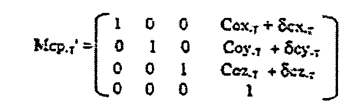
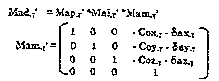
  • The transformation matrices of the elements shown in Eq. (4) are as follows.
    Figure 00220001
    Figure 00220002
    Figure 00220003
    Figure 00220004
    Figure 00220005
    Figure 00220006
  • The vector P-T of the instruction position P (x, y, z), the transformation matrix Mwo-T of the workpiece origin offset WO-T (WOx-T, WOy-T, WOz-T, 1)T, the matrix Mvt-T of the tool length vector Vt-T (0, 0, h, 1)T are as described above.
  • The vector P-T of the instruction position P (x, y, z) in the table coordinate system is multiplied by the matrix Mwo-T whereby the vector of the workpiece origin offset WO-T is added so that the instruction position in the machine coordinate system is computed, as shown in FIG. 8. The computed instruction position is multiplied by the transformation matrix Mcd-T' that includes the misalignment δc-T (δcx-T, δcy-T, δcz-T) of the C-axis in the direction of the X-, Y-, and Z-axes and the rotational misalignment (αc-T, βc-T, γc-T) of the C-axis about these X-, Y-, and Z-axes and the instruction c to the C-axis so that the misalignment of the C-axis is corrected, and the position resulting from the rotation of the C-axis by an equivalent of instruction c is computed. Further, this computed position is multiplied by the transformation matrix Mad-T' that includes the misalignment δa-T (δax-T, δay-T, δaz-T) of the A-axis in the direction of the X-, Y-, and Z-axes; the rotational misalignment (αa-T, βa-T, γa-T) of the A-axis about these X-, Y-, and Z-axes and the instruction a to the A-axis so that the misalignment of the A-axis is corrected, and the position resulting from the rotation of the A-axis by an equivalent of instruction a is computed. This computed position is multiplied by the matrix Mvt-T of the tool length vector Vt-T (0, 0, h, 1)T to compute the machine position Vm-T'.
  • 3. Embodiment 3 of the present invention (machine in which the tool head and the table rotate)
  • The third embodiment of the present invention is an example of a machine in which the table 3 is rotated about a rotating axis (C-axis), the tool head 1 is rotated about another rotating axis (B-axis), the C-axis rotates about the Z-axis, and the B-axis rotates about the Y-axis. The tool direction is the Z-axis direction when the positions of the axes of rotation are both zero (B and C = 0).
  • In the third embodiment, the following data is given as the initial conditions.
    • Tool length vector Vt-T (0, 0, h, 1)T
    • Workpiece origin offset WO-M (WOx-M, WOy-M, WOz-M, 1)T
    • Center of rotation of the C-axis Cc-M (Ccx-M, Ccy-M, Ccz-M, 1)T
    (3-1) Method for computing the machine position when there is no misalignment
  • In the third embodiment, the following computations are made and the machine position Vm-M (x, y, z, 1)T for which the tool length has been corrected is computed when positional instructions R (b, c) are given in relation to the B- and C-axes of rotation, and positional instruction values P (x, y, z) are given in the table coordinate system in relation to X, Y, and Z. If Vp-M = Mcd-M * Mwo-M * P-M and Vv-M = Mb-M * Vt-M then Vm-M = Vp-M + Vv-M
  • The elements in Eqs. (5) to (7) are as follows.
    Figure 00240001
    Figure 00240002
    Figure 00240003
    Figure 00240004
  • In other words, the vector P-M that shows the positional instruction values P (x, y, z) in the table coordinate system is multiplied by the matrix Mwo-M whereby the vector of the workpiece origin offset WO-M (WOx-M, WOy-M, WOz-M, 1)T is added, and then the result is multiplied by the rotation transformation matrix Mcd-M of the rotation instruction c for the C-axis to compute the instruction position Vp-M after the C-axis has been rotated by an equivalent of instruction c (Eq. (5)), as shown in FIG. 9.
  • The tool length vector Vt-M rotation is multiplied by the transformation matrix Mb-M whereby the B-axis is allowed to rotate by an equivalent of instruction b to compute the tool length vector Vt-M in which the B-axis has been rotated by an equivalent of instruction b (Eq. (6)).
  • The machine position Vm-M is determined by adding the tool length vector Vv-M in which the B-axis has been allowed to rotate by an equivalent of instruction b to the instruction position Vp-M after the C-axis has been rotated by an equivalent of instruction c, as shown in Eq. (7).
  • (3-2) Elements of misalignment (divergence and incline of the position of the center axis of rotation and the turning center of the spindle)
  • In the third embodiment (tool head and table rotary machine), it is assumed that there is (i) misalignment of the center of rotation of the C-axis, and (ii) misalignment of the center of rotation of the B-axis. Related items for these misalignments are represented by the following symbols.
  • Ac-M: Actual center of rotation of the C-axis
  • Cc-M: Original center of rotation of the C-axis (reference position)
  • Ab-M: Actual center of rotation of the B-axis
  • Cb-M: Original center of rotation of the B-axis (reference position)
  • (i) Misalignment of the center of rotation of the C-axis
  • The misalignment of the actual center of rotation of the C-axis Ac-M with respect to the original center of rotation of the C-axis (reference position) Cc-M is represented by the misalignment δc-M (δcx-M, δcy-M, δcz-M) in the direction of the X-, Y-, and Z-axes of linear motion, and the rotational misalignment (αc-M, βc-M, γc-M) about these X-, Y-, and Z-axes. Here, δc-M(δcx-M, δcy-M, δcz-M) are the X, Y, and Z components of the divergence distance from the actual center of rotation of the C-axis Ac-M to the original center of rotation of the C-axis Cc-M. Also, (αc-M, βc-M, γc-M) represents the misalignment whereby the actual center of rotation of the C-axis Ac-M is inclined by rotating αc-M about the X-axis, βc-M about the Y-axis and γc-M about the Z-axis from the original center of rotation of the C-axis Cc-M.
  • (ii) Misalignment of the center of rotation of the B-axis
  • The misalignment of the actual center of rotation of the B-axis Ab-M with respect to the original center of rotation of the B-axis (reference position) Cb-M is represented as follows. δb-M(δbx-M, δby-M, δbz-M) This misalignment is represented by the X, Y, and Z components of the distance of divergence from the original center of rotation of the B-axis Cb-M to the actual center of rotation of the B-axis Ab-M. Also, (αb-M, βb-M, γb-M) represents the fact that the actual center of rotation of the B-axis Ab-M is rotated αb-M about the X-axis, βb-M about the Y-axis, and γb-M about the Z-axis, and is inclined from the original center of rotation of the B-axis Cb-M.
  • It is assumed here that there is no misalignment with respect to the tool length vector Vt-M.
  • (3-3) Computing the machine position when there is misalignment
  • The machine position for a machine which has misalignment in the third embodiment is given by the following equations (Eq. (8) to Eq. (10)), in association with Eq. (5) to Eq. (7) which determines the position of a machine which has no misalignment, as described above. Vp-M' = Mcd-M' * Mwo-M * P-M Vv-M' = Mb-M' * δb-M * Vt-M Vm-M' = Vp-M' + Vv-M'
  • The elements in Eqs. (8) to (10) are as follows.
    Figure 00280001
    Figure 00280002
    Figure 00280003
    Figure 00280004
    Figure 00280005
  • In other words, the vector P-M that shows the positional instruction values P (x, y, z) in the table coordinate system is multiplied by the matrix Mwo-M whereby the vector of the workpiece origin offset WO-M (WOx-M, WOy-M, WOz-M, 1)T is added to compute the instruction position in the machine coordinate system, as shown in FIG. 10. This computed instruction position is then multiplied by the transformation matrix Mcd-M' that includes the instruction c for the C-axis, the rotation misalignment δc-M (δcx-M, δcy-M, δcz-M) of the C-axis in the direction of the X-, Y-, and Z-axes, and the rotational misalignment (αc-M, βc-M, γc-M) of the C-axis about these X-, Y-, and Z-axes so that the misalignment of the C-axis is corrected and the instruction position Vp-M in which the C-axis has been rotated by an equivalent of instruction c is computed (Eq. (8)).
  • The tool length vector Vt-M is multiplied by the matrix δb-M whereby the vector of the misalignment of the X, Y, and Z components of the B-axis is added so that the rotational misalignment of the B-axis is corrected, and the result is multiplied by the transformation matrix Mb-M' whereby the B-axis is rotated by an equivalent of instruction b so that the rotational misalignment of the B-axis is corrected, and the tool length vector Vv-M' in which the B-axis has been rotated by an equivalent of instruction b is computed (Eq. (9)).
  • The machine position Vm-M' is determined by adding the tool length vector Vv-M' in which the B-axis has been rotated by an equivalent of instruction b to the instruction position Vp-M' after the C-axis has been rotated by an equivalent of instruction c, as shown in Eq. (10).
  • (4) Other machines
  • The case in which the turning center of the spindle was misaligned from the reference position was described solely for tool head rotary machines, but application may also be made in the same manner to table rotary machines, and machines in which a tool head and a table rote.
  • The case in which the turning center of the spindle in a tool head rotary machine is misaligned from the reference position was described, but the present invention may also be applied to cases in which the turning center of the spindle is structurally not at the center of rotation of the axis of rotation on which the spindle is set, namely, to cases in which the turning center of the spindle Cs-H does not intersect with the center of rotation of the A-axis Ca-H, as shown in FIG. 11, or to the cases in which the center of rotation of the C-axis Cc-T and the center of rotation of the A-axis Ca-T do not intersect in machines in which a table rotates, as shown in FIG. 12.
  • The axes of rotation were assumed to be orthogonal in the case of a tool head rotary machine and in the case of a table rotary machine, but application may also be made to cases in which the axes of rotation are not orthogonal.
  • The structure of the axes of rotation in the above-described embodiments assumed the use of the C- and A-axes in the case of a tool head rotary machine, the A- and C-axes in the case of a table rotary machine, and the C- and B-axes in the case of a machine in which both the tool head and the table rotated, but application may also be made to machines with other axial structures; and application may also be naturally made to machines provided with only a single axis of rotation.
  • It was assumed that the tool direction was the Z-axis direction when the position of the axis of rotation was zero, but application may naturally be made to other axial directions.
  • FIG. 13 is a block diagram of a numerical control device that implements the methods in the embodiments for correcting the above-described misalignment and computing the machine position.
  • CPU 11 is a processor for the comprehensive control of a numerical control device 100. CPU 11 reads a system program stored in ROM 12 by way of a bus 20, and controls the entire numerical control device in accordance with the system program. Temporary calculation data, display data, and various data inputted by an operator by way of a display/MDI unit 70 are stored in RAM 13. A CMOS memory 14 is backed up with a battery (not depicted), and is structured as nonvolatile memory in which the storage condition is maintained even if the power supply for the numerical control device 100 is switched off. A work program read by way of an interface 15, a work program inputted by way of the display/MDI unit 70, and the like are stored in the CMOS memory 14. Software for performing calculations in accordance with Eqs. (1) to (10), which are used to implement the misalignment correction of the present invention, is also stored in the ROM 12.
  • Interface 15 is one with which it is possible to connect the numerical control device 100 with an adapter or other external equipment 72. Work programs and other data are read from external equipment 71. The work program compiled in the numerical control device 100 is capable of being stored in external storage means by way of the external equipment 72. PMC (programmable machine control device) 16 outputs signals to and controls an auxiliary device (an actuator such as a robot hand for tool replacement, for example) for a machine tool by way of an I/O unit 17 with the aid of a stored sequence program. PMC may sometimes be provided to the machine. Signals are received from switches and other devices on the control panel that is disposed on the main unit of the machine tool, any required signal processing is performed, and the data is thereafter delivered to CPU 11.
  • The display/MDI unit 70 is a manual data input device equipped with a display, a keyboard, and the like; and an interface 18 receives instructions and data from the keyboard of the CRT/MDI unit 70 and delivers these to CPU 11.
  • Axial control circuits 30 to 33 for the axes receive movement instruction values for the individual axes from CPU 11 and then output instructions for the axes to servo amplifiers 40 to 43. The servo amplifiers 40 to 43 receive the instructions and drive servomotors 50 to 53 for each axis (the X-, Y-, and Z-axes of linear motion, and the axes of rotation). The servomotors 50 to 53 for the axes include position and velocity detectors, the position and velocity feedback signals from the position and velocity detectors are fed back to the axial control circuits 30 to 33, and feedback control of the position and velocity is performed. The position and velocity feedback is omitted in FIG. 13.
  • A spindle control circuit 60 receives turning instructions for the spindle, and outputs a spindle velocity signal to a spindle amplifier 61. The spindle amplifier 61 receives the spindle velocity signal and causes a spindle motor 62 to rotate at the instructed rotational velocity. A position coder 63 provides a feedback pulse as feedback to the spindle control circuit 60 to control the velocity in synchronism with the rotation of the spindle motor 62.
  • The structure of the above-described numerical control device does not differ from the structure of a conventional numerical control device. However, functions not included in a conventional numerical control device have been added such that software for correcting the misalignment of a machine and outputting instruction positions is stored in storage means; the misalignment of divergence and incline of the center of an axis of rotation from the original position is corrected, the misalignment represented by the divergence and incline of the turning center of the spindle from the original position is corrected, movement instructions are outputted to the machine, as described above.
  • When mounting the numerical control device 100 in a machine, the above-described misalignment is set and registered in the numerical control device in accordance with the type of machine. That is to say, in the first embodiment, in which the machine is a tool head rotary machine with the A- and C-axes as the axes of rotation, δac-H (δacx-H, δacy-H, δacz-H) and (αc-H, βc-H, γc-H) are set as the misalignment of the C-axis, δa-H (δax-H, δay-H, δaz-H) and (αa-H, βa-H, γa-H) as the misalignment of the A-axis, and δs-H (δsx-H, δsy-H, δsz-H) and εs-H (αs-H, βs-H, γs-H) as the misalignment of the spindle.
  • In the case of the machine with a rotating table described as the second embodiment, δc-T (δcx-T, δcy-T, δcz-T) and (αc-T, βc-T, γc-T) are set as the misalignment of the C-axis, and δa-T (δax-T, δay-T, δaz-T) and (αa-T, βa-T, γa-T) as the misalignment of the A-axis. In the case of the machine described as the third embodiment, δc-M (δcx-M, δcy-M, δcz-M) and (αc-M, βc-M, γc-M) are set as the misalignment of the C-axis, and δb-M (δbx-M, δby-M, δbz-M) and (αb-M, βb-M, γb-M) as the misalignment of the B-axis.
  • These misalignment amounts may be set as parameters provided to the CMOS memory 14 or other means in the numerical control device 100. The error amounts of these may be stored in the machine in advance, and when the machine is connected to the numerical control device 100 the misalignment amount is transmitted from a PLC (programmable logic control device) provided to the machine, and the transmitted misalignment amount is set. The misalignment amount may be received by communication from an external computer by way of the interface 15 or other means, and may then be set.
  • The type of machine to be connected, in other words, a tool head rotary machine, a table rotary machine, a tool head and table rotary machine, or other type of machine may be set in the numerical control device 100. Other parameters that are set include the tool length, the workpiece origin (workpiece origin offset), the intersection between the center of rotation of the A-axis and the center of rotation of the C-axis in the case of a table rotary machine, and the position of the center of rotation of the C-axis in the case of a tool head and table rotary machine.
  • FIG. 14 is a processing flowchart for tool length correction executed by the numerical control device 100.
  • First, CPU 11 determines whether or not the misalignment amount is set (step 1); if the misalignment amount is not set, the machine structure (type) that has been set is determined (step 2); and if the machine is a tool head rotary machine, then processing for Eq. (1) is selected (step 3) and the calculation of Eq. (1) is thereafter performed for the positional instruction generated by the program to process the tool length correction.
  • If the machine is a table rotary machine, then processing for Eq. (3) is selected (step 4), and if the machine is one in which a tool head and a table rotate, then processing for Eqs. (5) to (7) is selected (step 5) and the selected processing is thereafter performed for the positional instruction generated by the program to process the tool length correction.
  • If the misalignment has been set, the machine structure (type) is determined (step 6); if the machine is a tool head rotary machine, then processing for Eq. (2) is selected (step 7); if the machine is a table rotary machine, then processing for Eq. (4) is selected (step 8); if the machine is one in which a tool head and a table rote, then processing for Eqs. (8) to (10) is selected (step 9); and the selected processing is thereafter performed for the positional instruction generated by the program to process the tool length correction.
  • It is possible to calculate the tool length correction at each block, but it is also possible to perform the calculation with an interpolated cycle, or with other timing provided in the numerical control device.
  • As described above, the present invention is capable of high precision work control because even if there is misalignment in the axis of rotation or the turning center of the spindle, the machine position in which the misalignment has been corrected is instructed.
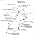
Claims (12)

  1. A numerical control device for controlling a machine having an axis of linear motion and at least one axis of rotation on a tool head or a table, said numerical control device comprising:
    means for obtaining a machine position to which the machine should actually move so that the relation between a workpiece and a tool that is found when there is no mechanical error is maintained on the basis of a reference position at which there is no mechanical error in the axis of rotation and an amount of misalignment of the actual axis of rotation from the reference position, and/or on the basis of a reference position at which there is no mechanical error in the turning center of the spindle and an amount of misalignment of the actual turning center of the spindle from the reference position of the turning center of the spindle; and
    drive control means for driving the axis of rotation and the axis of linear motion to the machine position obtained by said machine position obtaining means.
  2. The numerical control device according to claim 1, wherein said tool head of the machine rotates about at least one axis.
  3. The numerical control device according to claim 1, wherein said table of the machine rotates about at least one axis.
  4. The numerical control device according to claim 1, wherein said machine has the tool head and the table which rotate.
  5. The numerical control device according to any of claims 1 to 4, wherein said amount of misalignment is set by a parameter in the numerical control device.
  6. The numerical control device according to any of claims 1 to 4, wherein the amount of misalignment is delivered to the numerical control device by a signal from the machine to the numerical control device.
  7. The numerical control device according to any of claims 1 to 4, wherein the amount of misalignment is delivered to the numerical control device by a signal from external equipment to the numerical control device.
  8. A numerical control method that uses a numerical control device for a machine having an axis of linear motion and a least one axis of rotation on a tool head or a table, said method comprising the steps of:
    obtaining a machine position to which the machine should actually move so that the relation between a workpiece and a tool that is found when there is no mechanical error is maintained on the basis of a reference position at which there is no mechanical error in the axis of rotation and an amount of misalignment of the actual axis of rotation from the reference position, and/or on the basis of a reference position at which there is no mechanical error in the turning center of the spindle and an amount of misalignment of the actual turning center of the spindle from the reference position of the turning center of the spindle; and
    moving the axis of linear motion and the axis of rotation to the machine position thus obtained.
  9. The numerical control method according to claim 8, wherein the tool head of the machine rotates about at least one axis, and said method further comprising the steps of:
    correcting the tool length vector on the basis of a reference position at which there is no mechanical error in the axis of rotation and an amount of misalignment of the actual axis of rotation from the reference position, and/or a reference position at which there is no mechanical error in the turning center of the spindle, an amount of misalignment of the actual turning center of the spindle from the reference position of the turning center of the spindle, and instruction for the axis of rotation, and
    adding the instruction position vector to the corrected tool length vector and obtaining the machine position.
  10. The numerical control method according to claim 8, wherein the table of the machine rotates about at least one axis, said method further comprising the steps of:
    adding an offset of the origin of a table coordinate system to an instruction position in an table coordinate system and thereby obtaining an instruction position in the machine coordinate system; and
    correcting misalignment of the instruction position in the machine coordinate system on the basis of a reference position at which there is no mechanical error in the axis of rotation, an amount of misalignment of the actual axis of rotation from the reference position, and the instruction position for the axis of rotation, obtaining a position where the axis of rotation has rotated to the rotation position according to the instruction, and adding a tool length vector to the position to obtain the machine position.
  11. The numerical control method according to claim 8, wherein said machine has the tool head and table which rotate, said method comprising the steps of:
    adding an offset of the origin of a table coordinate system to a position instruction in the table coordinate system and thereby obtaining an instruction position in a machine coordinate system;
    obtaining an instruction position for which the misalignment has been corrected on the basis of an amount of misalignment of the actual axis of rotation provided to the table from a reference position at which there is no mechanical error in the axis of rotation and an instruction position for the axis of rotation;
    obtaining an attitude of the tool for which misalignment has been corrected on the basis of an amount of misalignment of the actual axis of rotation provided to the tool head from a reference position at which there is no mechanical error in an axis of rotation and the instruction position of the axis of rotation, in addition to a tool length vector; and
    obtaining a machine position from the instruction position for which the misalignment has been corrected and the attitude of the tool for which the misalignment has been corrected.
  12. The numerical control method according to any of claims 8 to 11, wherein the amount of misalignment is delivered to the numerical control device by means of a parameter setting in the numerical control device, a signal from the machine, or a signal from external equipment:
EP04250870A 2003-02-19 2004-02-18 Numerical control machine and method with misalignment correction Ceased EP1450224A1 (en)

Applications Claiming Priority (2)

Application Number Priority Date Filing Date Title
JP2003041249 2003-02-19

Publications (1)

Publication Number Publication Date
EP1450224A1 true EP1450224A1 (en) 2004-08-25

Family

ID=32732941

Family Applications (1)

Application Number Title Priority Date Filing Date
EP04250870A Ceased EP1450224A1 (en) 2003-02-19 2004-02-18 Numerical control machine and method with misalignment correction

Country Status (3)

Country Link
US (1) US7283889B2 (en)
EP (1) EP1450224A1 (en)
CN (1) CN1522829A (en)

Cited By (6)

* Cited by examiner, † Cited by third party
Publication number Priority date Publication date Assignee Title
EP1993013A3 (en) * 2007-05-17 2011-05-18 Fanuc Corporation Numerical control method for five-axis processing machine
DE102011015296B4 (en) * 2010-05-10 2013-05-16 Fanuc Corporation Numerical control for a multi-axis machine tool
EP2221692A3 (en) * 2007-11-02 2013-10-09 Makino Milling Machine Co. Ltd. Numerically controlled machine tool and numerical control device
US20140223751A1 (en) * 2011-10-19 2014-08-14 Spieth-Maschinenelemente Gmbh & Co. Kg Method for measuring a three-dimensional object
CN107824843A (en) * 2016-09-16 2018-03-23 发那科株式会社 Lathe and workpiece planarization processing method
CN114888386A (en) * 2022-06-07 2022-08-12 中国航发航空科技股份有限公司 Method for processing space vector hole

Families Citing this family (31)

* Cited by examiner, † Cited by third party
Publication number Priority date Publication date Assignee Title
US7090561B2 (en) * 2004-12-07 2006-08-15 General Electric Company Method and apparatus for pivot point determination and machine tool adjustment
US20070033785A1 (en) * 2005-08-09 2007-02-15 Kohring Mark D Ridge vent with biocidal source
CN100552586C (en) * 2005-09-12 2009-10-21 株式会社安川电机 Calibration device and method of returning to origin of calibration device, rotary table including calibration device, translational table, machine, and machine control system
JP4451381B2 (en) * 2005-12-02 2010-04-14 ヤマザキマザック株式会社 NC machining program creation method and NC machining program creation device of NC machining apparatus
DE102005061618B4 (en) * 2005-12-21 2018-12-27 Abb Ag System and method for alignment and position control of a robot tool
JP4902316B2 (en) * 2006-11-10 2012-03-21 東芝機械株式会社 Posture assurance system for 5-axis machine for oblique machining
JP5280665B2 (en) 2007-10-26 2013-09-04 オークマ株式会社 Numerical control device with manual shift operation function
JP4327894B2 (en) * 2007-11-30 2009-09-09 ファナック株式会社 Numerical control device for controlling a 5-axis machine
JP4609735B2 (en) * 2008-03-31 2011-01-12 ソニー株式会社 Information processing apparatus and method, program, and recording / reproducing apparatus
JP4503659B2 (en) * 2008-06-11 2010-07-14 ファナック株式会社 Numerical controller for coordinate transformation tool phase control
JP4653824B2 (en) * 2008-07-29 2011-03-16 ファナック株式会社 A machine tool system that measures the shape of a measurement object using an on-machine measuring device
US8010226B2 (en) * 2008-12-19 2011-08-30 The Boeing Company Apparatus and method for measuring and modifying components using reverse engineering
US7983790B2 (en) * 2008-12-19 2011-07-19 The Boeing Company Component repair using reverse engineering
WO2010109536A1 (en) * 2009-03-27 2010-09-30 三菱電機株式会社 Numerical control device and method of controlling the numerical control device
EP2539773B1 (en) * 2010-02-26 2014-04-16 Micronic Mydata AB Method and apparatus for performing pattern alignment
CN101870073B (en) * 2010-06-11 2012-02-29 华中科技大学 Multi-axis numerical control machining tool motion planning method based on process system rigidity characteristic
JP5014471B2 (en) 2010-06-30 2012-08-29 ファナック株式会社 Numerical controller for multi-axis machines
JP4938119B2 (en) * 2010-08-20 2012-05-23 ファナック株式会社 Numerical control device for multi-axis machines that controls tool tip position
CN102069419B (en) * 2010-12-19 2012-05-30 吉林大学 Ultraprecise free-form surface turning method of actively counteracting errors
CN103339575B (en) 2011-01-26 2015-07-22 三菱电机株式会社 CNC device
US8712577B2 (en) * 2011-02-23 2014-04-29 GM Global Technology Operations LLC Electronic system and method for compensating the dimensional accuracy of a 4-axis CNC machining system using global and local offsets
JP2014238782A (en) * 2013-06-10 2014-12-18 オークマ株式会社 Control method of machine tool
JP2015191306A (en) * 2014-03-27 2015-11-02 オークマ株式会社 Control method of machine tool, and control device
JP6184363B2 (en) * 2014-03-31 2017-08-23 オークマ株式会社 Method and apparatus for controlling machine tool
CN105373072A (en) * 2014-09-01 2016-03-02 富泰华工业(深圳)有限公司 High-precision plane processing system and method thereof
WO2016172452A1 (en) * 2015-04-23 2016-10-27 Massachusetts Institute Of Technology Discrete assemblers utilizing conventional motion systems
DE102015113890B4 (en) * 2015-08-21 2024-07-25 Gebr. Heller Maschinenfabrik Gmbh Machine tool with workpiece position and weight dependent deflection compensation
JP6845612B2 (en) * 2016-03-07 2021-03-17 中村留精密工業株式会社 Measurement method and equipment for machine accuracy in machine tools
EP3582043B1 (en) * 2018-06-12 2022-07-20 Siemens Aktiengesellschaft Method, numerical control device and machine tool for machining a workpiece
CN109290843B (en) * 2018-11-16 2021-02-05 西安科技大学 Prediction method of peak value of commutation error in inclined feed system of precision CNC machine tool
CN114518726B (en) * 2020-11-20 2024-02-20 航天科工惯性技术有限公司 Post-processing development method and device of four-axis half numerical control machine tool and numerical control machine tool equipment

Citations (2)

* Cited by examiner, † Cited by third party
Publication number Priority date Publication date Assignee Title
US4808048A (en) * 1986-10-02 1989-02-28 Johannes Heidenhain Gmbh Method and apparatus for error compensation
US20020049514A1 (en) * 2000-09-18 2002-04-25 Siemens Aktiengesellschaft Method for compensating for static position errors and orientation errors

Family Cites Families (8)

* Cited by examiner, † Cited by third party
Publication number Priority date Publication date Assignee Title
JPS56159707A (en) 1980-05-13 1981-12-09 Daihen Corp Controller of industrial robot
JPH0366549A (en) 1989-07-31 1991-03-22 Mitsubishi Heavy Ind Ltd Correcting method for straightness
JPH03109606A (en) 1989-09-22 1991-05-09 Fanuc Ltd Tool correction system
JPH05100723A (en) 1991-10-09 1993-04-23 Fanuc Ltd Tool length correcting system for machine tool
JPH07299697A (en) 1994-04-28 1995-11-14 Toshiba Mach Co Ltd Correcting method for installation error of workpiece and its correcting device
JPH10337636A (en) 1997-06-09 1998-12-22 Fanuc Ltd Control device for 5-shaft finishing machine
JP4198861B2 (en) 2000-03-23 2008-12-17 東芝機械株式会社 Correction method of machine error at spindle head of multi-axis machine tool
US6819974B1 (en) * 2000-03-29 2004-11-16 The Boeing Company Process for qualifying accuracy of a numerically controlled machining system

Patent Citations (2)

* Cited by examiner, † Cited by third party
Publication number Priority date Publication date Assignee Title
US4808048A (en) * 1986-10-02 1989-02-28 Johannes Heidenhain Gmbh Method and apparatus for error compensation
US20020049514A1 (en) * 2000-09-18 2002-04-25 Siemens Aktiengesellschaft Method for compensating for static position errors and orientation errors

Non-Patent Citations (2)

* Cited by examiner, † Cited by third party
Title
BOHEZ E L J: "Compensating for systematic errors in 5-axis NC machining", COMPUTER AIDED DESIGN, ELSEVIER PUBLISHERS BV., BARKING, GB, vol. 34, no. 5, 15 April 2002 (2002-04-15), pages 391 - 403, XP004332251, ISSN: 0010-4485 *
SOONS J A ET AL: "MODELLING THE ERRORS OF MULTI-AXIS MACHINES: A GENERAL METHODOLOGY", PRECISION ENGINEERING, GUILDFORD, SURREY, GB, vol. 14, no. 1, January 1992 (1992-01-01), pages 5 - 19, XP002120942 *

Cited By (12)

* Cited by examiner, † Cited by third party
Publication number Priority date Publication date Assignee Title
EP1993013A3 (en) * 2007-05-17 2011-05-18 Fanuc Corporation Numerical control method for five-axis processing machine
EP2390738A1 (en) * 2007-05-17 2011-11-30 Fanuc Corporation Numerical control method for five-axis processing machine
EP2221692A3 (en) * 2007-11-02 2013-10-09 Makino Milling Machine Co. Ltd. Numerically controlled machine tool and numerical control device
US8680806B2 (en) 2007-11-02 2014-03-25 Makino Milling Machine Co., Ltd. Numerically controlled machine tool and numerical control device
US8786243B2 (en) 2007-11-02 2014-07-22 Makino Milling Machine Co., Ltd. Method and device for preparing error map and numerically controlled machine tool having error map preparation function
DE102011015296B4 (en) * 2010-05-10 2013-05-16 Fanuc Corporation Numerical control for a multi-axis machine tool
US20140223751A1 (en) * 2011-10-19 2014-08-14 Spieth-Maschinenelemente Gmbh & Co. Kg Method for measuring a three-dimensional object
US9581423B2 (en) * 2011-10-19 2017-02-28 Spieth-Maschinenelemente Gmbh & Co. Kg Method for measuring a three-dimensional object
CN107824843A (en) * 2016-09-16 2018-03-23 发那科株式会社 Lathe and workpiece planarization processing method
CN107824843B (en) * 2016-09-16 2020-08-28 发那科株式会社 Machine tool and workpiece plane machining method
CN114888386A (en) * 2022-06-07 2022-08-12 中国航发航空科技股份有限公司 Method for processing space vector hole
CN114888386B (en) * 2022-06-07 2023-09-15 中国航发航空科技股份有限公司 Method for processing space vector hole

Also Published As

Publication number Publication date
US7283889B2 (en) 2007-10-16
CN1522829A (en) 2004-08-25
US20050107000A1 (en) 2005-05-19

Similar Documents

Publication Publication Date Title
EP1450224A1 (en) Numerical control machine and method with misalignment correction
JP4038185B2 (en) Numerical control method
US4659971A (en) Robot controlling system
US7969111B2 (en) Numerical controller for controlling a five-axis machining apparatus
EP0123214B1 (en) Operation teaching method and apparatus for industrial robot
US6775586B2 (en) Numerical controller
US9063536B2 (en) Numerical controller having workpiece mounting error compensation unit for three-axis machine tool
US20080154428A1 (en) Device, method, program and recording medium for robot offline programming
US4722063A (en) Method of calculating actual arm lengths and compensating for angular errors
US5392384A (en) Method of calibrating an industrial robot
US6897626B2 (en) Synchronous controller
US5563484A (en) Three-dimensional cutter compensation system
US5545959A (en) Speed control method for a numerical control apparatus
EP0480046A1 (en) Method of controlling attitude of cnc laser working machine
EP0533949A1 (en) Calibration system for industrial robot
US20150378343A1 (en) Numerical controller having tool tip point control function
EP0484539B1 (en) Cylinder interpolation system
KR100754008B1 (en) Robot controlling device and robot controlling method
US6150786A (en) Controller for industrial machine
EP0573962A2 (en) Numerical control device for tool driving along non-orthogonal mechanical axes
JP2960232B2 (en) Robot control device
JPH1020912A (en) Thermal displacement correcting method by numerical controller
JP2562353B2 (en) Robot positioning method
JPS62148173A (en) Method of adjusting origin of joint type robot
US12271174B2 (en) Numerical controller

Legal Events

Date Code Title Description
PUAI Public reference made under article 153(3) epc to a published international application that has entered the european phase

Free format text: ORIGINAL CODE: 0009012

AK Designated contracting states

Kind code of ref document: A1

Designated state(s): AT BE BG CH CY CZ DE DK EE ES FI FR GB GR HU IE IT LI LU MC NL PT RO SE SI SK TR

AX Request for extension of the european patent

Extension state: AL LT LV MK

17P Request for examination filed

Effective date: 20050216

AKX Designation fees paid

Designated state(s): DE

RBV Designated contracting states (corrected)

Designated state(s): DE

17Q First examination report despatched

Effective date: 20070102

STAA Information on the status of an ep patent application or granted ep patent

Free format text: STATUS: THE APPLICATION HAS BEEN REFUSED

18R Application refused

Effective date: 20070913