TECHNICAL FIELD
The present invention relates to a plastic optical
fiber formed by employing a resin for a core and a
cladding, and to an optical fiber cable.
BACKGROUND ART
Recently, various types of fluoropolymer plastic
optical fibers have been developed (for example, refer to
JP-A-6-194549), which employ a fluorine-containing resin
for a core 101 and a cladding 102 shown in Fig. 4, for
example, and which are suitable for using a near-infrared
light. For example, there is realized a plastic optical
fiber having a grated index type refractive index
distribution of the core, which can achieve a
transmission rate of at least 100 Mbps between two points
aparting at least 100 m from each other.
Further, there is a known plastic optical fiber of
this type which comprises a protection coating 103 (refer
to Fig. 4) employing a hydrocarbon type resin provided on
the outer periphery of the cladding 102, for
reinforcement. In the case of the plastic optical fiber
having the protection coating, when such a fiber of, for
example, about 1 m long (short distance) is used and, if
light is incident at an angle larger than the numerical
aperture (NA) of the core 101 of the optical fiber, the
light may propagate in the protection coating 103 by the
effect of the refractive index difference between the
protection coating 103 and air.
For example, in most cases, a focusing lens is
employed when a LD (laser diode) or a LED (light emitting
diode) is employed as a light source for an optical link.
However, when the focusing lens is not employed for
reducing the cost, light emitted from the LD or the LED
may spread before it is incident into the optical fiber,
and is incident also into the protection coating 103
besides the core 101. In this case, there is a
possibility that the light propagating in the protection
coating 103 causes a problem such as deterioration of a
receiving signal at the destination.
Further, when a near-infrared light having an
wavelength of at least, for example, 850 nm is used as
light to be transmitted in the protection coating 103,
the light is absorbed by hydrocarbon resin in the
protection coating 103. Accordingly, when the light is
transmitted with a length of at least 10 m, the light
transmitted through the protection coating 103 is not
observed at the destination.
However, when light having an wavelength of, for
example, 650 nm in a visible light region is used, the
absorption phenomenon by the hydrocarbon resin is not
likely to occur, and the light transmitted in the
protection coating 103 is observed at the destination in
some cases. Here, even when an infrared light having a
wavelength of at least 800 nm is used, pulses of light
propagating in the protection coating 103 reach a photo-detector
system at the destination in some cases if the
transmission length is short e.g. a few meters.
In a case where the pulses of such light are
incident in the photo-detector system, since the
protection coating 103 has a higher refractive index than
the core 101, the speed of light propagating in the
protection coating 103 is slower than that in the core
101. Therefore, the light propagating in the protection
coating 103 propagates slower than the light propagating
in the core 101, and they are observed as two separated
pulses at the photo-detector unit. As a result, there
occurs a problem that bit error is increased to
deteriorate the quality of digital communication.
Considering the above-mentioned circumstances, it is
an object of the present invention to provide a plastic
optical fiber in which unnecessary propagation light is
not propagated in a protection coating even in a case of
not employing a focusing lens combined with a light
source or in a case of using visible light or using an
infrared light in a short communication distance, thereby
performing high quality optical communication, and to
provide an optical fiber cable employing such a plastic
optical fiber.
DISCLOSURE OF THE INVENTION
The present invention provides a plastic optical
fiber comprising a core and a cladding each made of a
resin containing an appropriate material, and a
protection coating made of a hydrocarbon type resin
formed on the outer periphery of the cladding, wherein an
absorption layer containing a dye for absorbing light of
a specific wavelength or light in a specific wavelength
range is formed on the outermost portion of the
protection coating.
Further, the present invention provides the above-mentioned
plastic optical fiber, wherein the core and the
cladding are each made of a fluorine-containing resin.
Further, the present invention provides the plastic
optical fiber, wherein the absorption layer is
constituted to absorb at least light, incident into the
absorption layer from outside, having the same wavelength
as the light to be propagated in the core, by the effect
of the dye so that the light is prevented from entering
into the core and the cladding.
Further, the present invention provides any one of
the above-mentioned plastic optical fibers wherein the
absorption layer is formed by coating.
Further, the present invention provides the plastic
optical fiber wherein a pigment employing an inorganic
material, a pigment employing an organic material or a
pigment as a mixture of these pigments, is employed as
the dye.
Further, the present invention provides an optical
fiber cable comprising any one of the above-mentioned
plastic optical fibers.
BRIEF DESCRIPTION OF THE DRAWINGS
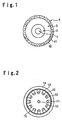
Fig. 1 is a cross-sectional schematic view showing
the construction of a fluoropolymer plastic optical
fiber according to an embodiment of the present
invention.
Fig. 2 is a cross-sectional schematic view showing
an example of an optical fiber cable employing the
fluoropolymer plastic optical fiber of the present
invention.
Fig. 3 is a cross-sectional schematic view showing
another example of an optical fiber cable employing the
fluoropolymer plastic optical fiber of the present
invention.
Fig. 4 is a cross-sectional schematic view showing
the construction of a conventional plastic optical fiber.
BEST MODE FOR CARRYING OUT THE INVENTION
Now, an embodiment of the present invention will be
described with reference to drawings.
Fig. 1 is a cross-sectional schematic view showing
the construction of a fluoropolymer plastic optical
fiber according to an embodiment of the present
invention.
The fluoropolymer plastic optical fiber of this
embodiment comprises a core 1, a cladding 2, a protection
coating 3 and a colored layer 4 in this order from the
center. In particular, the colored layer 4 contains in
its base material 41 a blue dye 42.
The core 1 is made of, for example, perfluorobutenyl
vinyl ether homopolymer containing a fluororesin
(refractive index n1=1.342) (tradename: Cytop
manufactured by Asahi Glass Co., Ltd.) as a base material
and a perfluoro compound having a higher refractive index
than the base material added as a dopant for increasing
the refractive index of the base material, and is formed
to have a diameter of 120 µm.
Further, the core 1 of this embodiment is formed,
for example, by a preforming method (or an extrusion
method) and subjected to e.g. a thermal diffusion method
to have a GI (grated index) construction having a
refractive index of 1.355 at the center and a refractive
index distribution close to a Gaussian distribution.
Here, the refractive index distribution of the core 1 may
be a SI (step index) type as well.
The cladding 2 is made of a perfluorobutenyl vinyl
ether homopolymer containing a fluororesin, which is the
same material as the base material of the core 1, has a
refractive index of n2=1.342 and is formed to have a
layer thickness of 115 µm (outer diameter: 230 µm).
According to the plastic optical fiber of the
present invention, the light dispersion in core and
cladding materials can be reduced because the core 1 and
the cladding 2 contain fluorine as described above.
Specifically, it has less light dispersion from a visible
region to a near infrared region as compared with other
plastic optical fibers such as an optical fiber made of
PMMA, and has less light dispersion in the visible region
as compared with silica optical fibers. Such reduction
of light dispersion becomes more remarkable by doping a
perfluoro compound into the core 1.
The protection coating 3 is made of a material in
which the fluorine content is positively excluded so that
it can absorb a (near) infrared light. In this
embodiment, it is made of a resin without containing
fluorine such as polymethyl methacrylate (PMMA) having a
refractive index of, for example, 1.492 and is formed to
have a thickness of 246 µm (outer diameter: 492 µm).
Here, the refractive index of this protection coating 3
is higher than that of the core 1 and the cladding 2 in
this embodiment. However, the opposite construction is
also acceptable.
Meanwhile, the absorption layer 4 is constituted so
that at least light incident into the absorption layer 4
from the outside, the light having the same wavelength as
the light propagating in the core 1, is absorbed by a dye
42 to be described later, and the incident light from the
side of the absorption layer 4 is prevented from entering
into the core 1 and the cladding 2. Further, a material
having higher refractive index than the protection
coating 3 is employed for the base material 41 in this
absorption layer 4, and the absorption layer 4 is formed
to have a thickness of, for example, about 7 µm. Here, a
UV-curable epoxy acrylate having a refractive index of
1.548 is employed as the base material 41 in this
embodiment, and it is formed by a pressure dice.
Further, considering mainly the wavelength of the
light to be transmitted, for example, considering that a
red light or light having a longer wavelength is used as
a signal light, the absorption layer 4 is formed to
contain the dye 42 of a color, for example, blue in this
embodiment, which can absorb external light having the
same wavelength as the wavelength of light to be
transmitted in the core 1, in order to prevent light
having such a wavelength from entering into the core 1
and the cladding 2 by absorbing the light even if the
light is incident from the outside.
Here, the dye 42 of this embodiment is constituted
by an appropriate inorganic material (such as TiO2 ZnO
or 2PbCO3) as a white pigment and an appropriate organic
material (such as a phthalocyanine, a dioxadine or an
anthraquinone) as a blue pigment mixed in the inorganic
material. Further, in the absorption layer 4 of this
embodiment, the dye 42 is mixed in the base material 41
in a mixing ratio of 15 wt%, and the refractive index is
higher (refractive index n=1.548) than that of the
protection coating 3. However, the mixing ratio is not
limited to this ratio.
Further, the absorption layer 4 is formed by coating
the outer periphery of the protection coating 3, and an
UV-curable resin is employed for the base material 41 and
the resin is UV-cured to increase the bond strength in
this embodiment. However, a thermosetting resin may be
employed for the base material 41 and cured by heat.
Here, a UV-curable resin is preferred for the base
material 41 from a viewpoint of productivity. There is
no particular restriction as to the refractive index of
the base material 41.
Therefore, according to the embodiment, since the
dye 42 is mixed in the absorption layer 4, even if light
is incident from the outside and transmitted through the
fluoropolymer plastic optical fiber, at least external
light having the same wavelength as the signal light
transmitted in the core 1 can be absorbed when it collide
with the dye 42 during its transmission in the absorption
layer 4. As a result, it is possible to prevent the
light from entering into the core 1 in the fluoropolymer
plastic optical fiber.
Here, with respect to the wavelength region to be
absorbed, since light in a near-infrared region is
employed for optical communications in these days, it is
preferred that the absorption effect is obtainable in the
wavelength region of from 500 to 1300 nm.
The present invention further provides an optical
fiber cable comprising the above-mentioned fluoropolymer
plastic optical fiber. There is no restriction as to
the construction and the structure of the optical fiber
cable itself, and ones shown in cross-sectional views of
Fig. 2 and Fig. 3 may be mentioned. Further, the
materials to be used may be known ones.
The optical fiber cable shown in Fig. 2 has a
tension member 10 at the center and the fluoropolymer
plastic optical fiber 20 as mentioned above is
accommodated in each of slots 11 of a slot rod 12 in
which a plurality of slots 11 are formed at the outer
periphery at equal intervals. Then, the outer periphery
is wrapped with a wrapping tape 13 and the entirety is
wrapped with a sheath 14. Here, a reference numeral 15
in the Figure designates a tearing string for easily
removing the sheath 14 so as to take out the
fluoropolymer plastic optical fibers 20 from the cable
at a time of branching. Further, the Figure shows a
construction of twelve fibers in which all twelve
fluoropolymer plastic optical fibers 20 are
accommodated. However, the numbers of the slots 11 and
the fluoropolymer plastic optical fibers 20 can be
optionally selected.
Further, as shown in Fig. 3, a plurality (four in
this embodiment) of the above-mentioned fluoropolymer
plastic optical fibers 20 can be accommodated in each
slot 11.
Here, in the case where a plurality of fluoropolymer
plastic optical fibers 20 are accommodated in each slot
11, the plurality of fluoropolymer plastic optical
fibers 20 may be coated as a whole to prevent the
fluoropolymer plastic optical fibers 20 from colliding
with each other by e.g. vibration. In this case, the
cable may be flattened as described in e.g. JP-A-11-231181
not shown. Further, a plurality of flattened
cables may be laminated as described in e.g. JP-A-11-202171.
Now, the function of this embodiment will be
described.
As described above, there is no restriction as to
the refractive index of the resin to be employed as the
base material 41 of the colored layer 4, and it may, for
example, be higher or lower than the refractive index of
the protection coating 3 (the refractive index of the
colored layer 4 is higher in this embodiment). Each of
these cases will be described.
Examples are described as follows.
EXAMPLE 1
With respect to a plastic optical fiber A of a
Comparative Example and a plastic optical fiber B of the
present invention, to be described later, each having a
length of 1.8 m, an experiment was carried out to compare
their propagation characteristics of signal light pulses.
Here, for the plastic optical fiber A of the
Comparative Example, a bare fiber was employed, which
comprises a cladding made of a perfluorobutenyl vinyl
ether homopolymer (refractive index n1=1.342) (tradename:
Cytop manufactured by Asahi Glass Co., Ltd.) and a core
formed inside the cladding in which a dopant having
higher refractive index than the cladding was diffused to
have a predetermined refractive index distribution. On
this bare fiber, a protection coating made of polymethyl
methacrylate (PMMA) was provided.
On the other hand, for the plastic optical fiber B
of the present invention, one comprising the same core 1,
cladding 2 and protection coating 3 as those of the
plastic optical fiber A of the Comparative Example, was
employed. Further, on the outer periphery of the
protection coating 3, an absorption layer 4 for which UV-curable
epoxy acrylate was used as the base material 41
and a blue dye was incorporated therein, was formed to be
7 µm thick by appropriately controlling the line speed
and the UV radiation intensity so that the heat amount
provided by a known UV radiation apparatus became less
than the softening heat amount of the plastic optical
fiber B. Here, the core diameters, the cladding
diameters and the protection coating diameters of these
optical fibers A and B were each equal to each other and
they were 120 µm, 230 µm and 492 µm respectively.
Further, a laser diode (wavelength: 810 nm; a near
infrared light) was employed as a light source, and
pulses of 50 ps (pico seconds) wide were let incident in
these plastic optical fibers A and B by using a lens
system having a NA=0.25. Here, incident-side end faces
of these optical fibers A and B were fixed to an optical
stage, so that the pulses could be incident at various
positions of the incident-side end faces by finely
adjusting the optical stage. Pulse waves from output-side end faces of these plastic optical fibers A and B
were observed by a sampling optical oscilloscope OOS-01
manufactured by Hamamatsu Photonics K.K.
From these results, it was confirmed that high
quality optical communication was possible.
EXAMPLE 2
A plastic optical fiber C was prepared, the fiber
comprising a core 1, a cladding 2 and a protection
coating 3 each being the same as those of the plastic
optical fiber of the Comparative Example in "Example 1",
and an absorption layer 4 formed on the outer periphery
of the protection coating 3, made of a UV-curable epoxy
acrylate as a base material 41 containing carbon black as
an inorganic pigment, the absorption layer being formed
to be 7 µm thick by properly controlling the line speed
and the UV radiation intensity so that heat amount
provided by a known UV radiation apparatus becomes less
than the softening heat amount of the plastic optical
fiber A. Here, the core diameter, the cladding diameter
and the protection coating diameter of the plastic
optical fiber C were the same as those of the plastic
optical fibers A and B, and they were 120 µm, 230 µm and
492 µm respectively. There was observed no pulse
propagating in the protection coating in the plastic
optical fiber C like the one in the plastic optical fiber
A.
Further, a UV radiation test was performed with
respect to the plastic optical fibers A and C. A bending
test at a bending radius of 15 mm was performed 1000
times with respect to each of these fibers to compare the
increase of the brittleness of the reinforcement layer.
As a result, the plastic optical fiber A was broken
within 1000 times of bending while there was no breakage
occurred in the plastic optical fiber C. Accordingly, it
is understood that UV rays are absorbed by carbon black,
whereby it becomes possible to prevent the protection
coating 3 from becoming brittle.
EXAMPLE 3
An example of the specifications of the optical
fiber cable is shown. Namely, as shown in Fig. 2, the
cable has a diameter of 11.5 mm, and has a tension member
10 made of a blueing steel wire having a diameter of 1.6
mm at the center of the cable. The plastic optical fiber
B prepared in "Example 1" is accommodated in each slot 11
of a slot rod 12 made of polyethylene which has twelve
slots 11 formed at equal intervals at its periphery.
Then, a wrapping tape 13 made of polyester of 30 mm wide
and 0.18 mm thick is wrapped three times around the slot
rod 12, and it is entirely covered with a sheath 14 made
of a non-flammable polyethylene having a thickness of 1.0
mm. Here, a tearing string 15 is made of a para-type all
aromatic polyamide fiber of 1000 denier.
INDUSTRIAL APPLICABILITY
As described above, the present invention provides a
plastic optical fiber comprising a core and a cladding
each made of a resin containing an appropriate material,
and a protection coating made of a hydrocarbon type resin
formed on the outer periphery of the cladding, wherein an
absorption layer containing a dye for absorbing light of
a specific wavelength or light in a specific wavelength
range formed as the outermost layer of the protection
coating, whereby it becomes possible to prevent light
from propagating in the protection coating which may
create a problem when the fiber of a short distance is
used for an optical transmission at a high bit rate, and
to prevent transmission errors from occurring.
Further, according to the present invention, an
expensive package of LD or LED with a lens which has been
used for focusing output light from the light source at
the core of a plastic optical fiber, or an external lens
which has been required besides the light source. become
unnecessary. In other words, even with an inexpensive LD
or LED packaged without a lens, the problem that the
signal light is propagated in the protection coating can
be prevented from occurring, whereby it becomes possible
to reduce the cost of a transmission apparatus.
Further, according to the present invention, an
absorption layer is provided as the outermost layer of
the plastic optical fiber, whereby even if light of the
same wavelength as signal light propagating in the core
of the plastic optical fiber is incident from the
outside, such light is absorbed by a dye in the
absorption layer and is prevented from entering into the
core to disturb the signal light. Accordingly, high
quality optical communication becomes possible.
Further, according to the present invention, it
becomes possible to prevent deterioration of the
protection coating due to UV rays contained in the sun
light or light from fluorescent lamps even if a plastic
optical fiber is laid out without being covered e.g. in a
cable.
Further, by providing a colored layer as the
outermost layer of the plastic optical fiber, each
plastic optical fiber can be easily identified in a case
where many plastic fibers are used as a group, whereby
various types of works can be performed efficiently to
the group of plastic optical fibers.
Further, the optical fiber cable of the present
invention comprises fluoropolymer plastic optical fibers
having the above-mentioned characteristics, whereby even
in a case of not employing a lens as a combination for
focusing light or in a case of using visible light or
using an infrared light in a short communication
distance, unnecessary propagation light can be removed
and high quality optical communication can be performed.