BACKGROUND OF THE INVENTION
This invention relates to improvements in an exhaust gas
purifying system, and more particularly to a technique for burning off
particulate (Particulate Matter in exhaust gas, referred hereafter to as
"PM") in exhaust gas collected in a filter, by raising the temperature of
exhaust gas.
In recent years, internal combustion engines, particularly diesel
engines are equipped with a Diesel Particulate Filter (referred
hereinafter to as "DPF") for collecting PM in exhaust gas. When the
amount of the collected PM reaches a certain level, the temperature of
exhaust gas is raised to burn off PM thereby regenerating DPF, as
disclosed in Japanese Patent Provisional Publication No. 2002-89327.
SUMMARY OF THE INVENTION
When the DPF is regenerated, a plurality of exhaust gas
temperature raising means are used together in order to effectively raise
the exhaust gas temperature. However, these means are different in
temperature rising sensitivity and influence on driveability of the engine,
and therefore the means suitable for raising the exhaust gas
temperature are different in accordance with engine operating regions.
Hitherto, such a fact has not been sufficiently taken into
consideration, and therefore it has occurred that the exhaust gas
temperature cannot be effectively raised and that the influence on the
driveability increases. This complicates a control for raising the exhaust
gas temperature, thereby making it difficult to smoothly converging the
exhaust gas temperature into a target level.
It is, therefore, an object of the present invention to provide an
improved exhaust gas purifying system for an internal combustion
engine, which can effectively overcome drawbacks encountered in
conventional exhaust gas purifying systems or similar techniques.
Another object of the present invention is to provide an improved
exhaust gas purifying system for an internal combustion engine, by
which a temperature of exhaust gas from the engine is effectively raised
thereby smoothly converging the exhaust gas temperature into a target
level, thus raising a burning-off and removing efficiency of PM and a
regeneration efficiency of DPF.
A further object of the present invention is to provide an improved
exhaust gas purifying system for an internal combustion engine, in
which a DPF regeneration control is accomplished taking account of the
fact that a device suitable for raising the exhaust gas temperature is
different depending upon an engine operating region.
An aspect of the present invention resides in an exhaust gas
purifying system for an internal combustion engine. The exhaust gas
purifying system comprises a particulate filter disposed in an exhaust
gas passageway of the engine to collect particulate in exhaust gas
flowing through the exhaust gas passageway. The collected particulate is
burnt off to be removed by raising a temperature of exhaust gas in a
condition in connection with the particulate filter. A plurality of devices
are provided for raising the temperature of exhaust gas to be introduced
into the particulate filter through the exhaust gas passageway when the
collected particulate is burned off to be removed. Additionally, a control
unit is configured to select at least one of the devices in accordance with
an engine operating region and preferentially operate the selected at
least one of the devices so as to raise the exhaust gas temperature.
Another aspect of the present invention resides in an exhaust gas
purifying system for an internal combustion engine. The exhaust gas
purifying system comprises particulate filter disposed in an exhaust gas
passageway of the engine to collect particulate in exhaust gas flowing
through the exhaust gas passageway. The collected particulate is burnt
off to be removed by raising a temperature of exhaust gas in a condition
in connection with the particulate filter. A plurality of devices are
provided for raising the temperature of exhaust gas to be introduced into
the particulate filter through the exhaust gas passageway when the
collected particulate is burned off to be removed. In the above
arrangement, at least one of the devices are selected in accordance with
an engine operating region and preferentially operated for raising the
exhaust gas temperature.
] A further aspect of the present invention resides in an exhaust
gas purifying system for an internal combustion engine. The exhaust gas
purifying system comprises a particulate filter disposed in an exhaust
gas passageway of the engine to collect particulate in exhaust gas
flowing through the exhaust gas passageway. The collected particulate is
burnt off to be removed by raising a temperature of exhaust gas in a
condition in connection with the particulate filter. A plurality of means
are provided for raising the temperature of exhaust gas to be introduced
into the particulate filter through the exhaust gas passageway when the
collected particulate is burned off to be removed. In the above
arrangement, at least one of the means are selected in accordance with
an engine operating region and preferentially operated for raising the
exhaust gas temperature.
A still further aspect of the present invention resides in a method
of operating an exhaust gas purifying system for an internal combustion
engine, the exhaust gas purifying system including a particulate filter
disposed in an exhaust gas passageway of the engine to collect
particulate in exhaust gas flowing through the exhaust gas passageway,
the collected particulate being burnt off to be removed by raising a
temperature of exhaust gas in a condition in connection with the
particulate filter; and a plurality of devices operated for raising the
temperature of exhaust gas to be introduced into the particulate filter
through the exhaust gas passageway when the collected particulate is
burned off to be removed. The operating method comprises (a) selecting
at least one of the devices in accordance with an engine operating region;
and (b) preferentially operating the selected at least one of the devices to
raise the exhaust gas temperature.
BRIEF DESCRIPTION OF THE DRAWINGS
Fig. 1A is a schematic illustration of an embodiment of an exhaust
gas purifying system according to the present invention, in combination
with an internal combustion engine;
Fig. 1B is a schematic block diagram of the exhaust gas purifying
system of Fig. 1A;
Fig. 2 is a flowchart showing a former stage of a control routine of
the exhaust gas purifying system of Fig. 1;
Fig. 3 is a flowchart showing a latter stage of the control routine
of the exhaust gas purifying system of Fig. 1;
Fig. 4 a graph showing a map for deciding an engine operating
region, used in the control routine of Figs. 2 and 3;
Fig. 5A is a table showing devices for raising an exhaust gas
temperature, used in the control routine of Figs. 2 and 3;
Fig. 5B is a table showing the device(s) preferentially used at first
and second steps in accordance with engine operating regions; and
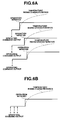
Figs. 6A and 6B are graphs illustrating such an operation of the
exhaust gas purifying system of Fig. 1 that a plurality of the devices are
controlled to have the same temperature rising characteristics for
exhaust gas.
DETAILED DESCRIPTION OF THE INVENTION
Referring now to Fig. 1A, an embodiment of an exhaust gas
purifying system is illustrated in combination with an internal
combustion engine 1 which is a diesel engine in this case. The engine 1 is
provided with a common rail fuel injection system which includes a
common rail 2 through which fuel is supplied to fuel injectors 3. Each
fuel injector 3 has an electromagnetic valve which is switched ON to
inject fuel and switched OFF to stop fuel injection. A fuel injection
amount (the amount of fuel injected from fuel injector 3) of fuel injector 3
is determined by a fuel injection control signal fed to fuel injector 3. The
common rail 2 is supplied with fuel from a fuel supply pump (not shown).
Engine 1 includes an exhaust manifold 4 through which exhaust
gas from the cylinders of engine 1 flows. Turbocharger 5 includes a
turbine 5T which is disposed downstream of exhaust manifold 4 so that
exhaust gas from exhaust manifold 4 is supplied to turbine 5T.
Compressor 5C of turbocharger 5 is disposed in an intake air passageway
6 through which intake air flows. Compressor 5C has a compressor wheel
(not shown) which is mounted on a common shaft on which a turbine
wheel of turbine 5T is mounted. Intake air is compressed by compressor
5C and thereafter flows through the intake air passageway 6 and
collector 7 to be sucked into the cylinders of engine 1. Throttle valve
(intake air control valve) 8 is disposed in the intake air passageway 6 to
control an intake air amount (the amount of intake air). Turbocharger 4
is of the variable capacity type and arranged to increase a turbine
efficiency so as to increase a supercharging pressure (an intake air
pressure developed by compressor 5C) by reducing an opening degree or
flow-path cross-sectional area of variable nozzle (VNT) of the
turbocharger by an actuator 51 disposed on the side of the turbine 5T
and to decrease the turbine efficiency so as to decrease the
supercharging pressure by increasing the flow-path cross-sectional area
of the variable nozzle. Supercharging pressure sensor 9 is disposed in
collector 7 in order to detect the supercharging pressure (the intake air
pressure).
EGR passage 10 is provided to connect exhaust manifold 4 with
the intake air passageway 10. EGR valve 11 is disposed in EGR passage
10 and adapted to control an EGR gas amount (the amount of EGR gas
flowing through the EGR passage) in accordance with an opening degree
of EGR valve 11.
Exhaust gas passageway 12 is formed through exhaust manifold 4
and extends through turbine 5T of turbocharger 5. DPF (Diesel
Particulate Filter) 13 is disposed in the exhaust gas passageway 12
downstream of the turbine 5T in order to collect or trap PM (Particulate
Matter) in exhaust gas. DPF 13 is provided with DPF temperature
sensor 14 in order to detect a temperature of DPF 13.
As shown in Fig. 1B, engine (electronic) control unit 15 is
electronically connected to fuel injector 3, throttle valve 8,
supercharging pressure sensor 9, EGR valve 11, DPF temperature sensor
14, actuator 51, engine speed sensor 31 adapted to detect an engine
speed of engine 1, and accelerator operating amount sensor 32 adapted to
detect an operating amount of an accelerator (pedal) shown in Fig. 1A.
Supercharging pressure sensor 9 is adapted to generate a supercharging
pressure signal representative of the supercharging pressure. DPF
temperature sensor 14 is adapted to generate a DPF temperature signal
representative of the DPF temperature. Engine speed sensor 31 is
adapted to generate an engine speed signal representative of the engine
speed. Accelerator operating amount sensor 32 is adapted to generate an
accelerator operating amount signal representative of the accelerator
operating amount. The supercharging pressure signal, the DPF
temperature signal, the engine speed signal and the accelerator
operating amount signal are input to the engine control unit 15, upon
which the engine control unit 15 outputs the fuel injection control signal
to fuel injector 3, a throttle valve control signal to throttle valve 8, an
EGR valve control signal to EGR valve 11 and a supercharging pressure
control signal to actuator 51 in accordance with the above-mentioned
signal(s) input to engine control unit 15.
The fuel injection control signal is representative of the fuel
injection amount in which fuel is injected from fuel injector 3. The
throttle valve control signal is representative of the intake air amount to
be determined by throttle valve 8. The EGR valve control signal is
representative of the EGR gas amount to be determined by EGR valve 11.
The supercharging pressure control signal is representative of the
supercharging pressure to be developed by compressor 5C of
turbocharger 5.
With the exhaust gas purifying system shown in Figs. 1A and 1B,
when DPF 13 is regenerated, an operation of raising the exhaust gas
temperature is carried out by using at least one of a plurality of devices
(means) for raising the exhaust gas temperature thereby accomplishing a
control for burning off and removing PM collected in DPF 13.
Next, a control of regeneration of DPF 13 will be discussed with
reference to flowcharts of Figs. 2 and 3.
At step S1, a decision is made as to whether a regeneration time
for DPF 13 has come or not. Specifically, an amount of PM collected by
DPF 13 is estimated by accumulating estimated amounts of PM in
exhaust gas emitted from the engine, each estimated PM amount varying
in accordance with engine operating condition, upon which the decision
of the generation time having come is made when the accumulated
estimated PM amounts reaches a certain level.
At step S2, a decision is made as to whether execution of an actual
DPF regeneration is to be made or not and for a regeneration level or
degree to be made for DPF 13 in accordance with an engine operating
region. When the decision of executing a partial generation of DPF 13 is
made in accordance with the engine operating region, a flow goes to step
S3 at which a BPT (Balance Point Temperature) control is made for a
certain time. The BPT control is to decrease the opening degree of
throttle valve 8 to obtain a target DPF temperature, for example, of 400
°C. By this, the intake air amount is reduced thereby raising a
temperature of exhaust gas, so that a part of PM collected in DPF 13 is
burnt off and removed thus partly regenerating DPF 13.
When the decision has been made such that execution of a control
for raising exhaust gas temperature largely affects an engine
performance in the engine operating region so as to be problematic at
step S2, the flow goes to step S4 at which regeneration of DPF 13 has
inhibited.
When the decision of executing a complete regeneration (in which
the whole collected PM is to be burnt off) of DPF 13 is made at step S2,
the flow goes to step S5 in order to execute a control for the complete
regeneration of DPF 13.
At step S5, a target DPF temperature is set. The target DPF
temperature is, for example, 570 °C in a first step (discussed after) and
670 °C in a second step (discussed after). Here, the temperature required
for burning off PM is a temperature of or in DPF 13 by which PM is
collected; however, the temperatures controlled by the respective devices
for raising the exhaust gas temperature is an exhaust gas temperature
(the temperature of exhaust gas from engine 1), so that the exhaust gas
temperature is controlled to become the above-mentioned target DPF
temperature. In other words, the target DPF temperature is a target
exhaust gas temperature (the target temperature of exhaust gas).
At step S6, in case of executing the complete regeneration of DPF
13, an operating region decision is made to decide the engine operating
region in order to select the device(s) preferentially used in accordance
with the engine operating region.
At step S7, the device(s) preferentially used at the first step is
determined or selected in accordance with the engine operating region
decided at step S6. The devices 1, 2, 3, 4, 5 and 6 for raising the exhaust
gas temperature are shown in Fig. 5A. More specifically, the
determination is made in accordance with Fig. 4 and Figs. 5A and 5B.
That is, in the engine operating region A (in Fig. 4) which is low in
engine speed and low in engine load, using or selecting the devices 1, 2, 3
and 4 is determined. The device 1 makes decreasing the intake air
amount by decreasing the opening degree of throttle valve 8. The device
2 makes controlling the (fuel) injection amount in a post injection in
expansion and exhaust strokes after a main injection (for combustion of
fuel in the cylinder), the injection amount at the post injection being
referred hereinafter to as "post injection amount". The device 3 makes
controlling a (fuel) injection timing in the post injection which timing is
referred hereinafter as "post injection timing". The device 4 makes
controlling the injection timing in the main injection which timing is
referred hereinafter to as "main injection timing". Here, when the post
injection amount is increased by the device 2, an after-burning amount
(the amount of fuel burnt after combustion in the cylinder) in DPF 13
increases thereby raising the DPF temperature. The post injection
timing by the device 3 is controlled in accordance with the post injection
amount. Retarding the main injection timing by the device 4 causes
combustion in the cylinder to be retarded, thereby raising the
temperature of exhaust gas from the cylinder or combustion chamber.
In the engine operating region B which is medium in engine speed
and low in engine load, using the devices 2, 3 and 4 preferentially at the
first step is determined. The device 2 makes controlling the post
injection amount. The device 3 makes controlling the post injection
timing. The device 4 makes controlling the main injection timing.
In the engine operating region C which is high in engine speed
and low in engine load, using the devices 2, 3 and 4 preferentially at the
first step is determined as same as in the engine operating region B. The
device 2 makes controlling the post injection amount. The device 3 makes
controlling the post injection timing. The device 4 makes controlling the
main injection timing.
In the engine operating region D which is medium in engine load
and low to medium in engine speed, using the devices 4, 5 and 6
preferentially at the first step is determined. The device 4 makes
controlling the main injection timing. The device 5 makes controlling an
opening degree of EGR valve 11 which is referred hereinafter to as "EGR
valve opening degree". The device 6 makes controlling the supercharging
pressure by controlling the opening degree of the variable nozzle (VNT)
of turbocharger 5 by actuator 51, the opening degree of the variable
nozzle being referred hereafter as to "VNT opening degree". Here, when
the EGR valve opening degree is increased so as to increase an EGR rate
(the rate of the EGR gas amount relative to the intake air amount), the
amount of EGR gas which is relatively high in temperature increases
thereby decreases the amount of fresh air which is relatively low in
temperature. As a result, the temperature of exhaust gas rises.
Additionally, when the opening degree of the variable nozzle (VNT) is
increased to decrease the supercharging pressure, the amount of fresh
air is decreased thereby raising the exhaust gas temperature.
In the engine operating region E which is medium in engine load
and medium to high in engine speed, using only the device 4
preferentially at the first step is determined. The device 4 makes
controlling the main injection timing.
In the engine operating region F which is high in engine load,
only the device 4 preferentially used at the first step is determined as
same as in the engine operating region E. The device 4 makes controlling
the main injection timing.
It will be seen that the functions of the devices 1 to 6 are
tabulated in Fig. 5A, and the devices preferentially used at the first step
in the respective engine operating ranges are tabulated in Fig. 5B.
At step 8, a time constant of each of the devices for raising the
exhaust gas temperature, determined at step S7 is set. More specifically,
when only one device is selected as in the engine operating region E and
the engine operating region F, the selected device 4 is immediately
operated. However, when a plurality of the devices are selected as in
other engine operating regions A to D, the time constant of each device is
set in order to make the devices the same in temperature raising
response. For example, in case that a delay time of each device between a
time at which an operating command (the command for operating the
device) is issued or output and a time at which the device is actually
operated is different among the plurality of the devices 1 to 6 as shown in
Fig. 6A, the outputs of the operating commands of other devices than the
device having the longest delay time are delayed such that operations of
the other devices are initiated at an operation initiating timing
(indicated as "Operation Initiated" in Fig. 6A) of the device having the
longest delay time.
At step S9, an increasing and decreasing control amount of each
device for raising the exhaust gas temperature is set. More specifically,
before the initiation of the regeneration control for DPF 13 is made, a
control amount of each device is set as a normal state control amount in
accordance with an engine operating condition and by means of a map or
the like. However, after the initiation of the DPF regeneration control,
the control amount of each device is set as the increasing and decreasing
control amount (or correction amount) in accordance with a deviation
between the above-mentioned target DPF temperature and an actual
DPF temperature detected by DPF temperature sensor 14 by means of a
map or the like separately provided, in order to raise the exhaust gas
temperature. Such setting the increasing and decreasing amount is made
only once at the initiation time of the DPF regeneration control, and is
by an open control different from a feedback control discussed after.
With the above settings, the DPF regeneration control at the first
step is executed by the preferentially selected device(s) in order to raise
the exhaust gas temperature.
Next, at step S10, a'decision is made as to whether the deviation
("the target DPF temperature - the actual DPF temperature") between
the above-mentioned target DPF temperature and the actual DPF
temperature is larger than a certain level or not, after lapse of a certain
time from the initiation of the DPF regeneration control at the first step.
When such a decision that the above-mentioned deviation has
decreased to a value of not larger than the certain level is made at step
10, the flow goes to step S11 at which the open control is changed into the
feedback control in order to converge the actual DPF temperature into
the target DPF temperature, successively detecting the actual DPF
temperatures.
When such a decision that the above-mentioned deviation (the
target DPF temperature - the actual DPF temperature) is larger than
the certain level is made at step 10, an exhaust gas temperature raising
degree upon the control by only the device(s) at the first step is judged to
be too low, and therefore the flow goes to step S12 for adding a control for
raising the exhaust gas temperature by the device(s) at a second step.
At step S12, the device(s) at the second step to be added are
determined or selected in accordance with the engine operating region.
Such determination is made in accordance with Fig. 4 and Figs. 5A and
5B.
More specifically, in the engine operating region A which is low in
engine speed and low in engine load, the devices 5 and 6 are determined
or selected as the devices at the second step to be added. The device 5
makes controlling the EGR valve opening degree. The device 6 makes
controlling the supercharging pressure.
In the engine operating region B which is medium in engine speed
and low in engine load, the devices 1, 5 and 6 are determined or selected
as the devices at the second step to be added. The device makes
decreasing the opening degree of throttle valve 8. The device 5 makes
controlling the EGR valve opening degree. The device 6 makes
controlling the supercharging pressure.
In the engine operating region C which is high in engine speed
and low in engine load, the device 6 is determined or selected as the
device at the second step to be added. The device 6 makes controlling the
supercharging pressure.
In the engine operating region D which is medium in engine load
and low to medium in engine speed, the devices 2 and 3 are determined
or selected as the devices at the second step to be added. The device 2
makes controlling the post injection amount. The device 3 makes
controlling the post injection timing.
In the engine operating region E which is medium in engine load
and low to medium in engine speed, the devices 2, 3 and 6 are
determined or selected as the devices at the second step to be added. The
device 2 makes controlling the post injection amount. The device 3 makes
controlling the post injection timing. The device 6 makes controlling the
supercharging pressure.
In the engine operating region F which is high in engine load,
only the device 6 is determined or selected as the device at the second
step to be added. The device 6 makes controlling the supercharging
pressure.
It will be seen that the devices preferentially used at the second
step in the respective engine operating ranges are tabulated in Fig. 5B.
At step S13, a time constant of each of the device(s) for raising the
exhaust gas temperature, determined at step S12 is set. More specifically,
similarly to the case where the time constant of each device at the first
step is set in step 8, when only one device is selected as in the engine
operating region C and the engine operating region F, the selected device
6 is immediately operated. However, when a plurality of the devices are
selected as in other engine operating regions A, B, D and E, the time
constant of each device is set in order to make temperature raising
responses of the respective devices at the same level. For example, in
case that a delay time of each device between the time at which the
operating command is issued and the time at which the device is actually
operated is different among the plurality of the devices 1 to 6, the
outputs of the operating commands of other devices than the device
having the longest delay time are delayed such that operations of the
other devices are initiated at the operation initiating timing of the device
having the longest delay time.
At step S14, similarly to the case of the control at the first step
executed at step S9, the increasing and decreasing control amount of
each device for raising the exhaust gas temperature is set.
At step S15, a decision is made as to whether a deviation (the
target DPF temperature ― actual DPF temperature) between the target
DPF temperature and the actual DPF temperature is larger than a
certain level or not after the DPF regeneration control at the second step
is added. When the deviation is decided to be larger than the certain
level, the flow goes back to step S12 at which a present control is
continued. When the deviation is decided to be lowered to a level of not
larger than the certain level, the flow goes to step S16 at which the open
control is changed into the feedback control in order to converge the
actual DPF temperature into the target DPF temperature similarly to at
step S11.
As discussed above, after the open control shifts to the feedback
control toward the target DPF temperature at steps 11 and 16, a decision
is made as to whether the regeneration of DPF has been completed or not
(i.e., the whole collected PM has been completely burned off or not) at
step 17. When the regeneration is decided to have been completed, the
flow goes to step S18 at which the exhaust gas temperature raising
control by the presently operated device(s) is stopped so that the exhaust
gas temperature raising control is changed into a normal state control,
thus completing the DPF regeneration control.
With the above discussed control, in the engine operating region A
which is low in engine speed and low in engine load so as to be small in
fuel injection amount and exhaust gas flow amount, a rising sensitivity
of exhaust gas temperature becomes high by reducing the amount of
fresh air upon decreasing the intake air amount or decreasing the
opening degree of the throttle valve, and therefore the decreasing the
intake air amount is preferentially made. However, since a loss due to
the intake air amount decreasing becomes large even at a low engine
load when the engine speed increases, the preference of using the device
for decreasing the intake air amount is lowered in a medium engine
speed engine operating region so that using the device is made in the
DPF regeneration control at the second step as an auxiliary measure.
Additionally, since an exhaust gas flow amount is small in the low
engine load engine operating regions A, B and C, the rising sensitivity of
the exhaust gas temperature due to the post injection by the devices 2
and 3 is high, and therefore the post injection is preferentially made.
However, influence of the post injection on a fuel consumption and an
engine performance appears with an increase in engine load, so that the
preference of the post injection is lowered in the medium engine load
engine operating regions D and E while the post injection is not made in
the high engine load engine operating region F.
Further, the EGR valve opening degree control by the device 5 is
preferentially made because the rising sensitivity of the exhaust gas
temperature is high in the medium engine load engine operating region
D in which the exhaust gas temperature is relatively high. However, in
the low engine load engine operating regions A and B, the EGR valve
opening degree control is executed upon lowering the preference thereof
because the EGR gas temperature is low so that the rising sensitivity of
the exhaust gas temperature is low in the engine operating regions. In
the high engine speed engine operating regions C and E and in the high
engine load engine operating region F, EGR largely affects a driveability
or power output of the engine, and therefore no EGR valve opening
degree control is executed.
Furthermore, in the low engine load engine operating region
where no supercharging is inherently executed, a supercharging
pressure decreasing effect (decreasing amount) is small so that the
exhaust gas temperature rising sensitivity is low, and therefore the
supercharging pressure control by the device 6 is executed upon lowering
the preference of the supercharging pressure control. In the medium
engine load engine operating region D, the supercharging pressure
decreasing effect (decreasing amount) increases so that the exhaust gas
temperature rising sensitivity is high, and therefore the supercharging
pressure control is preferentially executed. However, in the high engine
speed engine operating region C where the engine load is medium or
higher, and in the high engine load engine operating region F, a
supercharging pressure decrease largely affects the driveability or power
output of the engine, and therefore the supercharging pressure control is
executed upon lowering the preference thereof.
Furthermore, the exhaust gas temperature rising sensitivity by
retarding the main injection timing by the device 4 is high and slightly
affects the driveability of the engine in all the engine operating regions,
and therefore the retarding the main injection timing is preferentially
executed in all the engine operating regions.
Thus, the device(s) which are high in the exhaust gas temperature
rising sensitivity and slightly affects the driveability are preferentially
operated for each engine operating region. Additionally, the device(s)
which are low in the exhaust gas temperature rising sensitivity and
largely affects the driveability are operated upon being lowered in
preference or not operated. Accordingly, the exhaust gas temperature can
be smoothly converged into the target temperature thereby raising a
regeneration efficiency of DPF, maintaining the driveability at a suitable
level. Furthermore, when a plurality of the devices are selected to be
operated in the first step or the second step, the time constant of each
device is so set as to obtain the same temperature rising response, so
that the respective devices are initiated to be operated at the same time
thereby smoothly raising the temperature of exhaust gas to be supplied
to DPF. The feedback control made after raising the exhaust gas
temperature can be stably accomplished.
The entire contents of Japanese Patent Application P2003-019312
(filed January 28, 2003) are incorporated herein by reference.
Although the invention has been described above by reference to
certain embodiments of the invention, the invention is not limited to the
embodiments described above. Modifications and variations of the
embodiments described above will occur to those skilled in the art, in
light of the above teachings. The scope of the invention is defined with
reference to the following claims.