EP1449954A1 - Low-noise household clothes drying machine - Google Patents
Low-noise household clothes drying machine Download PDFInfo
- Publication number
- EP1449954A1 EP1449954A1 EP03027525A EP03027525A EP1449954A1 EP 1449954 A1 EP1449954 A1 EP 1449954A1 EP 03027525 A EP03027525 A EP 03027525A EP 03027525 A EP03027525 A EP 03027525A EP 1449954 A1 EP1449954 A1 EP 1449954A1
- Authority
- EP
- European Patent Office
- Prior art keywords
- arm
- drying machine
- clothes drying
- contact
- drum
- Prior art date
- Legal status (The legal status is an assumption and is not a legal conclusion. Google has not performed a legal analysis and makes no representation as to the accuracy of the status listed.)
- Granted
Links
- 238000001035 drying Methods 0.000 title claims abstract description 27
- 239000007787 solid Substances 0.000 claims abstract description 15
- 238000000926 separation method Methods 0.000 abstract 1
- 230000006872 improvement Effects 0.000 description 8
- 238000005259 measurement Methods 0.000 description 7
- 239000002184 metal Substances 0.000 description 4
- 238000010276 construction Methods 0.000 description 2
- 230000000694 effects Effects 0.000 description 2
- 238000000034 method Methods 0.000 description 2
- 238000012986 modification Methods 0.000 description 2
- 230000004048 modification Effects 0.000 description 2
- 230000004075 alteration Effects 0.000 description 1
- 230000002547 anomalous effect Effects 0.000 description 1
- 230000002860 competitive effect Effects 0.000 description 1
- 239000004020 conductor Substances 0.000 description 1
- 238000001514 detection method Methods 0.000 description 1
- 238000006073 displacement reaction Methods 0.000 description 1
- 239000000463 material Substances 0.000 description 1
- 230000009467 reduction Effects 0.000 description 1
- 238000007493 shaping process Methods 0.000 description 1
- 238000005406 washing Methods 0.000 description 1
Images


Classifications
-
- D—TEXTILES; PAPER
- D06—TREATMENT OF TEXTILES OR THE LIKE; LAUNDERING; FLEXIBLE MATERIALS NOT OTHERWISE PROVIDED FOR
- D06F—LAUNDERING, DRYING, IRONING, PRESSING OR FOLDING TEXTILE ARTICLES
- D06F34/00—Details of control systems for washing machines, washer-dryers or laundry dryers
- D06F34/14—Arrangements for detecting or measuring specific parameters
- D06F34/18—Condition of the laundry, e.g. nature or weight
-
- D—TEXTILES; PAPER
- D06—TREATMENT OF TEXTILES OR THE LIKE; LAUNDERING; FLEXIBLE MATERIALS NOT OTHERWISE PROVIDED FOR
- D06F—LAUNDERING, DRYING, IRONING, PRESSING OR FOLDING TEXTILE ARTICLES
- D06F2103/00—Parameters monitored or detected for the control of domestic laundry washing machines, washer-dryers or laundry dryers
- D06F2103/02—Characteristics of laundry or load
- D06F2103/08—Humidity
- D06F2103/10—Humidity expressed as capacitance or resistance
-
- D—TEXTILES; PAPER
- D06—TREATMENT OF TEXTILES OR THE LIKE; LAUNDERING; FLEXIBLE MATERIALS NOT OTHERWISE PROVIDED FOR
- D06F—LAUNDERING, DRYING, IRONING, PRESSING OR FOLDING TEXTILE ARTICLES
- D06F58/00—Domestic laundry dryers
- D06F58/32—Control of operations performed in domestic laundry dryers
- D06F58/34—Control of operations performed in domestic laundry dryers characterised by the purpose or target of the control
- D06F58/36—Control of operational steps, e.g. for optimisation or improvement of operational steps depending on the condition of the laundry
- D06F58/38—Control of operational steps, e.g. for optimisation or improvement of operational steps depending on the condition of the laundry of drying, e.g. to achieve the target humidity
-
- D—TEXTILES; PAPER
- D06—TREATMENT OF TEXTILES OR THE LIKE; LAUNDERING; FLEXIBLE MATERIALS NOT OTHERWISE PROVIDED FOR
- D06F—LAUNDERING, DRYING, IRONING, PRESSING OR FOLDING TEXTILE ARTICLES
- D06F58/00—Domestic laundry dryers
- D06F58/32—Control of operations performed in domestic laundry dryers
- D06F58/34—Control of operations performed in domestic laundry dryers characterised by the purpose or target of the control
- D06F58/52—Preventing or reducing noise
Definitions
- the present invention refers to an improved kind of clothes drying machine, preferably of the type for use in households, which is particularly quiet in its operation.
- a number of systems are known and used to so measure the moisture content remaining in the clothes, and therefore to so detect the degree of dryness reached by the same clothes, these systems being based substantially on two concepts, i.e. the measurement of temperature and the measurement of conductivity.
- control means are rather accurate in their operation. As hinted above, they are based on the measurement of the conductivity of the clothes, which is known to normally vary in accordance with the moisture content of the same clothes.
- drums may also be nonconductive, provided of course that the instantaneous contact surfaces thereof, i.e. the surfaces thereof that are in contact with the brushes, are conductive.
- the concept is that the varying moisture content in the clothes being dried affects the conductivity thereof, so that the actual dryness degree of the clothes can be detected by measuring the conductivity being detectable between said two electrically isolated half-shells, which form the drum and in this way become the "terminals" of a series circuit, in which the element to be measured is exactly constituted by the clothes in contact with both said half-shells.
- Said brushes are in turn connected independently to control means of an appropriate kind, which according to generally known methods are capable of detecting the conductivity measured between such brushes and letting the operating cycle of the machine be performed and controlled in accordance with the detected value of such conductivity.
- the drum must rub against said brushes and, owing to the latter being made in the shape of small cylinders or prisms of a conductive material, with the longer sides thereof arranged in a substantially orthogonal manner relative to the rotating surface of the respective half-shell, by so moving relative to and against each other, said surfaces generate a peculiar sliding noise (of the kind generally perceived when writing on a blackboard with a piece of chalk), which proves to be even more annoying owing to its being continuous throughout the drying cycle, which the machine may take even hours to bring to completion.
- clothes drying machine must be able to be easily manufactured using existing, readily available materials and techniques, and be competitive in its construction; it shall in particular be able to be implemented with a minimum extent of modifications having to be introduced in currently produced clothes drying machine designs; it shall in addition be able to incorporate all these modifications and improvements without suffering any alteration or reduction in the performance abilities and the reliability thereof.
- a clothes drying machine comprises a drying drum comprised of two distinct substantially cylindrical half-shells 1, 2 made of metal and joined to each other on the side of a mutually facing base thereof.
- the above-cited half-shells are joined to each other via an electrically insulating annular separating member 3 disposed therebetween, so that said half-shells are practically isolated from each other.
- Each one of said half-shells is associated to a respective brush comprising:
- the above-mentioned brush is made and provided in such a manner that, when it is applied to the respective half-shell, the related articulation enables both the sliding solid conductive member 4 to adapt to the surface of the half-shell 1, on which it is able to slide in a much more effective and quiet manner as compared with prior-art sliding contacts.
- a first improvement consists in that the two axes Y and Z of the first pin 5A and the second pin 7A, respectively, are parallel not only to each other, but also to the instantaneous contact surface 10 (illustrated symbolically in Figures 2A and 4A), between a half-shell 1 and the respective sliding solid conductive member 4.
- a second improvement relates to the geometry of said first arm 5.
- This arm is in fact provided in such a manner that, as this is illustrated in Figure 2A, the vector of the force F acting on said first arm 5, and exerted by the second arm 6 towards the instantaneous contact surface 10, lies inside the two extremities 12, 13 of the sliding solid conductive member 4 with respect to the relative sliding direction H thereof; in a more general way, the vector of said force F must intercept the instantaneous contact surface 10 in a position inside the half space delimited by the two parallel planes A, B passing through said two extremities 12, 13 and extending orthogonally to said relative sliding direction H.
- a third improvement consists in providing said second arm 6 and said third arm 7 with an elastic member 14 so that said first pin 5A is constantly biased towards and against the contact surface, thereby pushing said sliding solid contact member 4 in the same direction.
- the aggregate effect of the above-described improvements enables a considerable amplitude to be obtained as far as the capability of movement of the sliding contact member 4 orthogonally to the instantaneous contact surface 10 is concerned, the sliding contact member 4 itself being in this way enabled to very well adapt to and cater for any possible irregularity or unevenness of said surface. Furthermore, the pressure being so exerted turns out as being significantly constant, thanks also to the considerable capability of said second arm to oscillate.
- a fourth improvement lies in the fact that said brush is not applied to the outer cylindrical surface of the half-shell, actually, but rather to a planar wall 14 constituting a base therefore and extending orthogonally to the axis of rotation X of the same half-shell, as shown in Figures 4 and 7.
- annular surface 16 there may be identified an annular surface 16, as this is shown in Figure 7, which is progressively exposed to the contact and, therefore, the sliding movement of said brush.
- a further improvement can be obtained by minimizing the contact or sliding surface, however without thereby impairing the reliability and constancy of the contact.
- This is achieved by shaping said sliding member 4 in such a manner as to provide it with at least an edge 15, and by orienting said edge in such a manner as to enable it to act as the sole sliding contact surface of said brush.
- said edge be oriented in a substantially orthogonal manner with respect to said two pins 5A, 7A, so that the relative tangential velocity of the shell at an intermediate point of the sliding solid member 4 is parallel to the edge in contact therewith.
Landscapes
- Engineering & Computer Science (AREA)
- Textile Engineering (AREA)
- Detail Structures Of Washing Machines And Dryers (AREA)
- Main Body Construction Of Washing Machines And Laundry Dryers (AREA)
- Drying Of Solid Materials (AREA)
- Detergent Compositions (AREA)
Abstract
- a rotating drum including two cylindrical half-shells joined to each other via an intermediate insulating separation member,
- a pair of electric sliding brushes, each one of which arranged in contact with a respective one of said half-shells,
Description
- The present invention refers to an improved kind of clothes drying machine, preferably of the type for use in households, which is particularly quiet in its operation.
- Largely known in the art is the general requirement for the noise generated by household appliances in their operation to be reduced as much as possible; also largely known in the art is the fact that in clothes washing machines use is largely made of the measurement of the residual moisture in the clothes in order to correspondingly control the operating programme of the machine in an adequate manner, in particular in order to be able to calculate in advance the moment at which the drying process must be concluded, and the related cycle terminated, so as to obtain the desired result.
- A number of systems are known and used to so measure the moisture content remaining in the clothes, and therefore to so detect the degree of dryness reached by the same clothes, these systems being based substantially on two concepts, i.e. the measurement of temperature and the measurement of conductivity.
- In the following description, reference will be made to clothes drying machines that are provided with means for controlling the dryness degree of the clothes based on the conductivity measurement concept.
- These control means are rather accurate in their operation. As hinted above, they are based on the measurement of the conductivity of the clothes, which is known to normally vary in accordance with the moisture content of the same clothes.
- On the other hand, these systems call for the use of rather sophisticated control devices; furthermore, as this is described for instance in EP 0106283, the clothes drying machine must be equipped with a metal rotating drum comprised of two half-shells separated from each other by a ring-shaped insulating member.
- There are also clothes drying machines on the market, which are provided actually with a single-piece rotating drum, but are equipped with internal devices for the detection of the conductivity of the clothes, and are anyway provided with at least an outer brush applied onto a circular planar base of the drum; in this case, these drums may also be nonconductive, provided of course that the instantaneous contact surfaces thereof, i.e. the surfaces thereof that are in contact with the brushes, are conductive.
- According to the prior-art, the concept is that the varying moisture content in the clothes being dried affects the conductivity thereof, so that the actual dryness degree of the clothes can be detected by measuring the conductivity being detectable between said two electrically isolated half-shells, which form the drum and in this way become the "terminals" of a series circuit, in which the element to be measured is exactly constituted by the clothes in contact with both said half-shells.
- In order to be able to perform such measurement on said two rotating half-shells of the drum, the practice is known of having said two half-shells made of metal and a pair of so-called metal and, therefore, electrically conductive "brushes" arranged in an appropriate position in contact therewith, each one of said brushes being provided so as to maintain a fixed position relative to the structure of the machine, and being further pressed against the respective half-shell in such a manner as to establish a continuous electric contact therewith, especially when said half-shells are rotating.
- Said brushes are in turn connected independently to control means of an appropriate kind, which according to generally known methods are capable of detecting the conductivity measured between such brushes and letting the operating cycle of the machine be performed and controlled in accordance with the detected value of such conductivity.
- However, during its rotation, the drum must rub against said brushes and, owing to the latter being made in the shape of small cylinders or prisms of a conductive material, with the longer sides thereof arranged in a substantially orthogonal manner relative to the rotating surface of the respective half-shell, by so moving relative to and against each other, said surfaces generate a peculiar sliding noise (of the kind generally perceived when writing on a blackboard with a piece of chalk), which proves to be even more annoying owing to its being continuous throughout the drying cycle, which the machine may take even hours to bring to completion.
- In addition, the fact that the contact surface of said brushes is rather limited and, above all, the fact that said brushes are so arranged as being oriented "head-on" relative to the surface of the drum, practically cause each even quite slight unevenness or irregularity in the contact zone to in turn cause the brush to undergo a kind of micro-leap, thereby leading to a temporary loss of electric contact with unfavourable consequences as far as a correct operation of the machine is concerned.
- A further drawback of prior-art solutions is encountered when, owing to a contact member being pressed "head-on" against the rotating surface, and this contact member being usually fitted in a seat that is orthogonal to the contact surface, it can be noticed that there takes place a kind of dragging effect of said contact by the surface of the drum, which leads to an anomalous, asymmetrical wear-out of the parts concerned. Furthermore, owing to the clearances of said contact member within the seat in which it is accommodated, the same contact member is oriented in a definite direction with the relative motion of the drum taking place in a given direction; when the direction of said motion changes, the contact is caused to undergo a jolt, i.e. to leap, and for a certain period of time it follows the motion of the drum without rubbing thereagainst, thereby giving rise to obvious drawbacks; moreover, owing to the different orientation it offers a contact surface that is different from the just quitted one, this practically meaning a typical additional noise resulting as a consequence thereof.
- It would therefore be desirable, and it is actually a main purpose of the present invention, to provide a clothes drying machine operating according to the control principle based on the measurement of the conductivity, which is provided with at least a brush arranged upon an appropriate rotating half-shell, and which however does not show the afore-noted drawback of an excessive noise being generated.
- Furthermore, such clothes drying machine must be able to be easily manufactured using existing, readily available materials and techniques, and be competitive in its construction; it shall in particular be able to be implemented with a minimum extent of modifications having to be introduced in currently produced clothes drying machine designs; it shall in addition be able to incorporate all these modifications and improvements without suffering any alteration or reduction in the performance abilities and the reliability thereof.
- According to the present invention, these aims are reached in a clothes drying machine incorporating such operating and control means as described below by mere way of non-limiting example with reference to the accompanying drawings, in which:
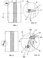
- Figures 1 and 1A are a side view of a drum with a brush according to the present invention and an enlarged view of a detail thereof, respectively;
- Figures 2 and 2A are again a side view, from a position turned by a right angle with respect to the view appearing in Figure 1, of a drum with a brush according to the present invention and an enlarged view of a detail thereof, respectively;
- Figures 3 and 3A are a front view of a drum with a brush according to the present invention and an enlarged view of a detail thereof, respectively, according to an improved embodiment thereof;
- Figures 4 and 4A are a perspective view of a drum with a brush according to the present invention and an enlarged view of a detail thereof, respectively, according to an improved embodiment thereof;
- Figures 5 and 5A and Figure 6 are three respective orthogonal views of the brush according to the present invention, as illustrated individually;
- Figure 7 is a perspective view of the brush shown in the preceding Figures, as illustrated individually.
- With reference to the above-listed Figures, a clothes drying machine according to the present invention comprises a drying drum comprised of two distinct substantially cylindrical half-
shells - The above-cited half-shells are joined to each other via an electrically insulating annular separating
member 3 disposed therebetween, so that said half-shells are practically isolated from each other. - Each one of said half-shells is associated to a respective brush comprising:
- a solid
conductive member 4, - an articulation including a
first arm 5 firmly joined to said solid member, asecond arm 6 and athird arm 7, in which saidsecond arm 6 is rotatably connected by means of a joint or a hinge to appropriate points of saidfirst arm 5 and saidthird arm 7 with the use of hinging orsimilar pins third arm 7 is secured in a firmly joined manner to an appropriate portion of the structure of the machine (not shown). - As illustrated in Figures 1A, 2A and 3A, the above-mentioned brush is made and provided in such a manner that, when it is applied to the respective half-shell, the related articulation enables both the sliding solid
conductive member 4 to adapt to the surface of the half-shell 1, on which it is able to slide in a much more effective and quiet manner as compared with prior-art sliding contacts. - To this purpose, following measures must be taken and following construction improvements musty be introduced.
- A first improvement consists in that the two axes Y and Z of the
first pin 5A and thesecond pin 7A, respectively, are parallel not only to each other, but also to the instantaneous contact surface 10 (illustrated symbolically in Figures 2A and 4A), between a half-shell 1 and the respective sliding solidconductive member 4. - A second improvement relates to the geometry of said
first arm 5. This arm is in fact provided in such a manner that, as this is illustrated in Figure 2A, the vector of the force F acting on saidfirst arm 5, and exerted by thesecond arm 6 towards theinstantaneous contact surface 10, lies inside the twoextremities conductive member 4 with respect to the relative sliding direction H thereof; in a more general way, the vector of said force F must intercept theinstantaneous contact surface 10 in a position inside the half space delimited by the two parallel planes A, B passing through said twoextremities - A third improvement consists in providing said
second arm 6 and saidthird arm 7 with anelastic member 14 so that saidfirst pin 5A is constantly biased towards and against the contact surface, thereby pushing said slidingsolid contact member 4 in the same direction. - Owing to the third arm being anchored to the structure of the machine, the aggregate effect of the above-described improvements enables a considerable amplitude to be obtained as far as the capability of movement of the sliding
contact member 4 orthogonally to theinstantaneous contact surface 10 is concerned, the slidingcontact member 4 itself being in this way enabled to very well adapt to and cater for any possible irregularity or unevenness of said surface. Furthermore, the pressure being so exerted turns out as being significantly constant, thanks also to the considerable capability of said second arm to oscillate. - A fourth improvement lies in the fact that said brush is not applied to the outer cylindrical surface of the half-shell, actually, but rather to a
planar wall 14 constituting a base therefore and extending orthogonally to the axis of rotation X of the same half-shell, as shown in Figures 4 and 7. - In this way, on said planar wall there may be identified an
annular surface 16, as this is shown in Figure 7, which is progressively exposed to the contact and, therefore, the sliding movement of said brush. - This solution enables the amplitude of displacement of the
second arm 6 to be minimized and, at the same time, the assembly work to be facilitated, owing to the fact that said planar wall is much more accessible and even, as well as far less oscillating than the cylindrical surface of the half-shells. - A further improvement can be obtained by minimizing the contact or sliding surface, however without thereby impairing the reliability and constancy of the contact. This is achieved by shaping said sliding
member 4 in such a manner as to provide it with at least anedge 15, and by orienting said edge in such a manner as to enable it to act as the sole sliding contact surface of said brush. However, for said sliding contact surface to be minimized also on the half-shell side, it is highly preferable that said edge be oriented in a substantially orthogonal manner with respect to said twopins solid member 4 is parallel to the edge in contact therewith. - It will of course be appreciated that the above-described solution has been illustrated as an example of possible embodiments of the present invention, and that the same solution may therefore be applied to both the brushes of a drum comprised of two half-shells and the brushes of a drum that is substantially comprised of a single shell, which may even be nonconductive.
Claims (8)
- Clothes drying machine comprising:characterized in that at least one of said electric brushes comprises a solid electric-contact member (4) articulated with the structure of said clothes drying machine by means of at least three distinct arms (5, 6, 7), of which a first arm (5) is firmly joined to said solid member, a second arm (6) is connected between said first arm and a third arm (7), the latter being firmly joined to the structure of the machine.a rotating drum for holding and drying the clothes to be dried, possibly comprised of two half-shells (1, 2),external means adapted to circulate a controlled flow of heated-up air within and through said drum,means adapted to rotatably drive said drum in a pre-established manner about an axis of rotation (X) coinciding with the axes of said two half-shells,a pair of electric sliding-contact brushes, each one of which being arranged in contact with a respective portion of said drum,said clothes drying machine being adapted to carry out a pre-established sequence of operating phases comprising at least a drying phase,
- Clothes drying machine according to claim 1, characterized in that said second arm (6) is rotatably connected to said first arm and said third arm by means of two respective pins or hinges (5A, 7A).
- Clothes drying machine according to claim 2, characterized in that said two pins are provided with respective axes (Y, Z) extending parallel to each other, as well as to the instantaneous electric-contact surface (10) of said solid member (4).
- Clothes drying machine according to any of the preceding claims, characterized in that the contact surface of said drum, or a portion thereof, is a ring-shaped surface (16) arranged on a planar base and extending orthogonally to the axis of rotation thereof.
- Clothes drying machine according to claim 2 or 3, characterized in that between said second arm and said third arm there is provided an elastic member (14) adapted to bias against said contact surface the extremity of said first arm that is hinged on said second arm.
- Clothes drying machine according to any of the preceding claims or combination thereof, characterized in that said solid electric-contact member (4) has at least an edge (15), and that said edge forms the zone being in contact with the respective half-shell (1).
- Clothes drying machine according to claim 6, characterized in that said edge is oriented orthogonally relative to said two pins (5A, 7A), so that said edge (15) is parallel to the tangential velocity of the drum in the instantaneous contact surface.
- Clothes drying machine according to any of the preceding claims or combination thereof, characterized in that the vector of the force (F) acting on said pin (5A), which is provided between said first arm and said second arm, intercepts said instantaneous contact surface (10) at a point inside the half space delimited by the two parallel planes (A, B) passing through the two opposite extremities (12, 13) of said solid member and extending orthogonally to said instantaneous contact surface.
Applications Claiming Priority (2)
| Application Number | Priority Date | Filing Date | Title |
|---|---|---|---|
| ITPN20030004U | 2003-02-19 | ||
| IT000004U ITPN20030004U1 (en) | 2003-02-19 | 2003-02-19 | QUIET DOMESTIC DRYER |
Publications (2)
| Publication Number | Publication Date |
|---|---|
| EP1449954A1 true EP1449954A1 (en) | 2004-08-25 |
| EP1449954B1 EP1449954B1 (en) | 2008-06-25 |
Family
ID=32732613
Family Applications (1)
| Application Number | Title | Priority Date | Filing Date |
|---|---|---|---|
| EP03027525A Expired - Lifetime EP1449954B1 (en) | 2003-02-19 | 2003-11-29 | Low-noise household clothes drying machine |
Country Status (5)
| Country | Link |
|---|---|
| EP (1) | EP1449954B1 (en) |
| AT (1) | ATE399223T1 (en) |
| DE (1) | DE60321766D1 (en) |
| ES (1) | ES2309269T3 (en) |
| IT (1) | ITPN20030004U1 (en) |
Cited By (4)
| Publication number | Priority date | Publication date | Assignee | Title |
|---|---|---|---|---|
| EP1816251A3 (en) * | 2006-02-07 | 2008-06-25 | Miele & Cie. KG | Support device for clamping to a supporting structure, in particular to the casing of a domestic appliance |
| CN1854381B (en) * | 2005-04-25 | 2010-04-28 | 海尔集团公司 | A new type of dryer |
| EP2796610A1 (en) | 2013-04-24 | 2014-10-29 | Miele & Cie. KG | Sensor for detecting residual moisture in laundry in a laundry drum of a laundry dryer and laundry dryer using such a sensor |
| EP2796609A1 (en) | 2013-04-24 | 2014-10-29 | Miele & Cie. KG | Sensor for detecting residual moisture in a drum of a laundry dryer |
Citations (3)
| Publication number | Priority date | Publication date | Assignee | Title |
|---|---|---|---|---|
| EP0106283A2 (en) * | 1982-10-08 | 1984-04-25 | INDUSTRIE ZANUSSI S.p.A. | Improved laundry dryer |
| EP0351608A1 (en) * | 1988-07-22 | 1990-01-24 | INDUSTRIE ZANUSSI S.p.A. | A drying machine for laundry |
| DE4437635A1 (en) * | 1994-10-21 | 1996-04-25 | Miele & Cie | Laundry dryer |
-
2003
- 2003-02-19 IT IT000004U patent/ITPN20030004U1/en unknown
- 2003-11-29 ES ES03027525T patent/ES2309269T3/en not_active Expired - Lifetime
- 2003-11-29 EP EP03027525A patent/EP1449954B1/en not_active Expired - Lifetime
- 2003-11-29 DE DE60321766T patent/DE60321766D1/en not_active Expired - Lifetime
- 2003-11-29 AT AT03027525T patent/ATE399223T1/en not_active IP Right Cessation
Patent Citations (3)
| Publication number | Priority date | Publication date | Assignee | Title |
|---|---|---|---|---|
| EP0106283A2 (en) * | 1982-10-08 | 1984-04-25 | INDUSTRIE ZANUSSI S.p.A. | Improved laundry dryer |
| EP0351608A1 (en) * | 1988-07-22 | 1990-01-24 | INDUSTRIE ZANUSSI S.p.A. | A drying machine for laundry |
| DE4437635A1 (en) * | 1994-10-21 | 1996-04-25 | Miele & Cie | Laundry dryer |
Cited By (6)
| Publication number | Priority date | Publication date | Assignee | Title |
|---|---|---|---|---|
| CN1854381B (en) * | 2005-04-25 | 2010-04-28 | 海尔集团公司 | A new type of dryer |
| EP1816251A3 (en) * | 2006-02-07 | 2008-06-25 | Miele & Cie. KG | Support device for clamping to a supporting structure, in particular to the casing of a domestic appliance |
| EP2796610A1 (en) | 2013-04-24 | 2014-10-29 | Miele & Cie. KG | Sensor for detecting residual moisture in laundry in a laundry drum of a laundry dryer and laundry dryer using such a sensor |
| EP2796609A1 (en) | 2013-04-24 | 2014-10-29 | Miele & Cie. KG | Sensor for detecting residual moisture in a drum of a laundry dryer |
| DE102013104118A1 (en) * | 2013-04-24 | 2014-10-30 | Miele & Cie. Kg | Probe for detecting the residual moisture of laundry located in a drum of a tumble dryer |
| DE102013106431A1 (en) * | 2013-04-24 | 2014-10-30 | Miele & Cie. Kg | Button for detecting the residual moisture of laundry in a drum of a tumble dryer |
Also Published As
| Publication number | Publication date |
|---|---|
| EP1449954B1 (en) | 2008-06-25 |
| ES2309269T3 (en) | 2008-12-16 |
| ATE399223T1 (en) | 2008-07-15 |
| DE60321766D1 (en) | 2008-08-07 |
| ITPN20030004U1 (en) | 2004-08-20 |
Similar Documents
| Publication | Publication Date | Title |
|---|---|---|
| AU2003220738B2 (en) | Sensor assembly for automatic dryer | |
| EP1961858A1 (en) | Laundry dryer | |
| EP1449954B1 (en) | Low-noise household clothes drying machine | |
| US20150233039A1 (en) | Laundry treatment apparatus | |
| EP2837721B1 (en) | Laundry appliance provided with a control-panel assembly | |
| JP2014018608A (en) | Clothes dryer | |
| JP5957685B2 (en) | Drum dryer | |
| CN209039818U (en) | Dryer door hinge and dryer | |
| EP1914341B1 (en) | Drying machine | |
| GB2169135A (en) | Improvements in electric power control switches | |
| EP4187009B1 (en) | A household appliance comprising a knob | |
| JPS615884A (en) | washing machine lid switch | |
| WO2018202546A1 (en) | Carrier for detecting dryness and washer/dryer wherein the carrier is used | |
| EP1683907A1 (en) | Contact band for a moisture measuring circuit and dryer provided therewith | |
| EP0351608A1 (en) | A drying machine for laundry | |
| RU2809674C2 (en) | Low voltage contact group | |
| KR101394510B1 (en) | An electrode sensor of laundry treatment machine and laundry treatment machine including the electrode sensor | |
| US2286720A (en) | Washing machine | |
| JP2013085790A (en) | Cloths dryer | |
| JP3381054B2 (en) | Shoes dryer with auxiliary function for dehydration | |
| JPH0366918B2 (en) | ||
| WO2026005595A1 (en) | A cable force measuring device | |
| JPH0366919B2 (en) | ||
| JPH0339195Y2 (en) | ||
| SU473384A3 (en) | Switch |
Legal Events
| Date | Code | Title | Description |
|---|---|---|---|
| PUAI | Public reference made under article 153(3) epc to a published international application that has entered the european phase |
Free format text: ORIGINAL CODE: 0009012 |
|
| AK | Designated contracting states |
Kind code of ref document: A1 Designated state(s): AT BE BG CH CY CZ DE DK EE ES FI FR GB GR HU IE IT LI LU MC NL PT RO SE SI SK TR |
|
| AX | Request for extension of the european patent |
Extension state: AL LT LV MK |
|
| 17P | Request for examination filed |
Effective date: 20040911 |
|
| AKX | Designation fees paid |
Designated state(s): AT BE BG CH CY CZ DE DK EE ES FI FR GB GR HU IE IT LI LU MC NL PT RO SE SI SK TR |
|
| GRAP | Despatch of communication of intention to grant a patent |
Free format text: ORIGINAL CODE: EPIDOSNIGR1 |
|
| GRAS | Grant fee paid |
Free format text: ORIGINAL CODE: EPIDOSNIGR3 |
|
| GRAA | (expected) grant |
Free format text: ORIGINAL CODE: 0009210 |
|
| AK | Designated contracting states |
Kind code of ref document: B1 Designated state(s): AT BE BG CH CY CZ DE DK EE ES FI FR GB GR HU IE IT LI LU MC NL PT RO SE SI SK TR |
|
| REG | Reference to a national code |
Ref country code: GB Ref legal event code: FG4D |
|
| REG | Reference to a national code |
Ref country code: CH Ref legal event code: EP |
|
| REF | Corresponds to: |
Ref document number: 60321766 Country of ref document: DE Date of ref document: 20080807 Kind code of ref document: P |
|
| REG | Reference to a national code |
Ref country code: IE Ref legal event code: FG4D |
|
| PG25 | Lapsed in a contracting state [announced via postgrant information from national office to epo] |
Ref country code: SI Free format text: LAPSE BECAUSE OF FAILURE TO SUBMIT A TRANSLATION OF THE DESCRIPTION OR TO PAY THE FEE WITHIN THE PRESCRIBED TIME-LIMIT Effective date: 20080625 Ref country code: FI Free format text: LAPSE BECAUSE OF FAILURE TO SUBMIT A TRANSLATION OF THE DESCRIPTION OR TO PAY THE FEE WITHIN THE PRESCRIBED TIME-LIMIT Effective date: 20080625 |
|
| PG25 | Lapsed in a contracting state [announced via postgrant information from national office to epo] |
Ref country code: NL Free format text: LAPSE BECAUSE OF FAILURE TO SUBMIT A TRANSLATION OF THE DESCRIPTION OR TO PAY THE FEE WITHIN THE PRESCRIBED TIME-LIMIT Effective date: 20080625 Ref country code: AT Free format text: LAPSE BECAUSE OF FAILURE TO SUBMIT A TRANSLATION OF THE DESCRIPTION OR TO PAY THE FEE WITHIN THE PRESCRIBED TIME-LIMIT Effective date: 20080625 |
|
| REG | Reference to a national code |
Ref country code: ES Ref legal event code: FG2A Ref document number: 2309269 Country of ref document: ES Kind code of ref document: T3 |
|
| NLV1 | Nl: lapsed or annulled due to failure to fulfill the requirements of art. 29p and 29m of the patents act | ||
| PG25 | Lapsed in a contracting state [announced via postgrant information from national office to epo] |
Ref country code: CZ Free format text: LAPSE BECAUSE OF FAILURE TO SUBMIT A TRANSLATION OF THE DESCRIPTION OR TO PAY THE FEE WITHIN THE PRESCRIBED TIME-LIMIT Effective date: 20080625 Ref country code: PT Free format text: LAPSE BECAUSE OF FAILURE TO SUBMIT A TRANSLATION OF THE DESCRIPTION OR TO PAY THE FEE WITHIN THE PRESCRIBED TIME-LIMIT Effective date: 20081125 Ref country code: SE Free format text: LAPSE BECAUSE OF FAILURE TO SUBMIT A TRANSLATION OF THE DESCRIPTION OR TO PAY THE FEE WITHIN THE PRESCRIBED TIME-LIMIT Effective date: 20080925 |
|
| PG25 | Lapsed in a contracting state [announced via postgrant information from national office to epo] |
Ref country code: SK Free format text: LAPSE BECAUSE OF FAILURE TO SUBMIT A TRANSLATION OF THE DESCRIPTION OR TO PAY THE FEE WITHIN THE PRESCRIBED TIME-LIMIT Effective date: 20080625 Ref country code: RO Free format text: LAPSE BECAUSE OF FAILURE TO SUBMIT A TRANSLATION OF THE DESCRIPTION OR TO PAY THE FEE WITHIN THE PRESCRIBED TIME-LIMIT Effective date: 20080625 Ref country code: BE Free format text: LAPSE BECAUSE OF FAILURE TO SUBMIT A TRANSLATION OF THE DESCRIPTION OR TO PAY THE FEE WITHIN THE PRESCRIBED TIME-LIMIT Effective date: 20080625 |
|
| PG25 | Lapsed in a contracting state [announced via postgrant information from national office to epo] |
Ref country code: EE Free format text: LAPSE BECAUSE OF FAILURE TO SUBMIT A TRANSLATION OF THE DESCRIPTION OR TO PAY THE FEE WITHIN THE PRESCRIBED TIME-LIMIT Effective date: 20080625 Ref country code: BG Free format text: LAPSE BECAUSE OF FAILURE TO SUBMIT A TRANSLATION OF THE DESCRIPTION OR TO PAY THE FEE WITHIN THE PRESCRIBED TIME-LIMIT Effective date: 20080925 Ref country code: DK Free format text: LAPSE BECAUSE OF FAILURE TO SUBMIT A TRANSLATION OF THE DESCRIPTION OR TO PAY THE FEE WITHIN THE PRESCRIBED TIME-LIMIT Effective date: 20080625 |
|
| PLBE | No opposition filed within time limit |
Free format text: ORIGINAL CODE: 0009261 |
|
| STAA | Information on the status of an ep patent application or granted ep patent |
Free format text: STATUS: NO OPPOSITION FILED WITHIN TIME LIMIT |
|
| 26N | No opposition filed |
Effective date: 20090326 |
|
| PG25 | Lapsed in a contracting state [announced via postgrant information from national office to epo] |
Ref country code: MC Free format text: LAPSE BECAUSE OF NON-PAYMENT OF DUE FEES Effective date: 20081130 |
|
| REG | Reference to a national code |
Ref country code: CH Ref legal event code: PL |
|
| PG25 | Lapsed in a contracting state [announced via postgrant information from national office to epo] |
Ref country code: LI Free format text: LAPSE BECAUSE OF NON-PAYMENT OF DUE FEES Effective date: 20081130 Ref country code: IE Free format text: LAPSE BECAUSE OF NON-PAYMENT OF DUE FEES Effective date: 20081129 Ref country code: CH Free format text: LAPSE BECAUSE OF NON-PAYMENT OF DUE FEES Effective date: 20081130 |
|
| PG25 | Lapsed in a contracting state [announced via postgrant information from national office to epo] |
Ref country code: LU Free format text: LAPSE BECAUSE OF NON-PAYMENT OF DUE FEES Effective date: 20081129 Ref country code: CY Free format text: LAPSE BECAUSE OF FAILURE TO SUBMIT A TRANSLATION OF THE DESCRIPTION OR TO PAY THE FEE WITHIN THE PRESCRIBED TIME-LIMIT Effective date: 20080625 Ref country code: HU Free format text: LAPSE BECAUSE OF FAILURE TO SUBMIT A TRANSLATION OF THE DESCRIPTION OR TO PAY THE FEE WITHIN THE PRESCRIBED TIME-LIMIT Effective date: 20081226 |
|
| PG25 | Lapsed in a contracting state [announced via postgrant information from national office to epo] |
Ref country code: TR Free format text: LAPSE BECAUSE OF FAILURE TO SUBMIT A TRANSLATION OF THE DESCRIPTION OR TO PAY THE FEE WITHIN THE PRESCRIBED TIME-LIMIT Effective date: 20080625 |
|
| PG25 | Lapsed in a contracting state [announced via postgrant information from national office to epo] |
Ref country code: GR Free format text: LAPSE BECAUSE OF FAILURE TO SUBMIT A TRANSLATION OF THE DESCRIPTION OR TO PAY THE FEE WITHIN THE PRESCRIBED TIME-LIMIT Effective date: 20080926 |
|
| PGFP | Annual fee paid to national office [announced via postgrant information from national office to epo] |
Ref country code: ES Payment date: 20121122 Year of fee payment: 10 |
|
| PGFP | Annual fee paid to national office [announced via postgrant information from national office to epo] |
Ref country code: DE Payment date: 20131121 Year of fee payment: 11 Ref country code: GB Payment date: 20131120 Year of fee payment: 11 Ref country code: FR Payment date: 20131120 Year of fee payment: 11 |
|
| PGFP | Annual fee paid to national office [announced via postgrant information from national office to epo] |
Ref country code: IT Payment date: 20131127 Year of fee payment: 11 |
|
| REG | Reference to a national code |
Ref country code: DE Ref legal event code: R119 Ref document number: 60321766 Country of ref document: DE |
|
| REG | Reference to a national code |
Ref country code: ES Ref legal event code: FD2A Effective date: 20150709 |
|
| GBPC | Gb: european patent ceased through non-payment of renewal fee |
Effective date: 20141129 |
|
| PG25 | Lapsed in a contracting state [announced via postgrant information from national office to epo] |
Ref country code: ES Free format text: LAPSE BECAUSE OF NON-PAYMENT OF DUE FEES Effective date: 20131130 |
|
| REG | Reference to a national code |
Ref country code: FR Ref legal event code: ST Effective date: 20150731 |
|
| PG25 | Lapsed in a contracting state [announced via postgrant information from national office to epo] |
Ref country code: DE Free format text: LAPSE BECAUSE OF NON-PAYMENT OF DUE FEES Effective date: 20150602 Ref country code: GB Free format text: LAPSE BECAUSE OF NON-PAYMENT OF DUE FEES Effective date: 20141129 |
|
| PG25 | Lapsed in a contracting state [announced via postgrant information from national office to epo] |
Ref country code: FR Free format text: LAPSE BECAUSE OF NON-PAYMENT OF DUE FEES Effective date: 20141201 |
|
| PG25 | Lapsed in a contracting state [announced via postgrant information from national office to epo] |
Ref country code: IT Free format text: LAPSE BECAUSE OF NON-PAYMENT OF DUE FEES Effective date: 20141129 |