EP1449784A1 - Spout for pouch and plastic pouch with spout fixed thereto - Google Patents
Spout for pouch and plastic pouch with spout fixed thereto Download PDFInfo
- Publication number
- EP1449784A1 EP1449784A1 EP02767946A EP02767946A EP1449784A1 EP 1449784 A1 EP1449784 A1 EP 1449784A1 EP 02767946 A EP02767946 A EP 02767946A EP 02767946 A EP02767946 A EP 02767946A EP 1449784 A1 EP1449784 A1 EP 1449784A1
- Authority
- EP
- European Patent Office
- Prior art keywords
- spout
- pouch
- end portion
- seal part
- heat
- Prior art date
- Legal status (The legal status is an assumption and is not a legal conclusion. Google has not performed a legal analysis and makes no representation as to the accuracy of the status listed.)
- Withdrawn
Links
Images


Classifications
-
- B—PERFORMING OPERATIONS; TRANSPORTING
- B65—CONVEYING; PACKING; STORING; HANDLING THIN OR FILAMENTARY MATERIAL
- B65D—CONTAINERS FOR STORAGE OR TRANSPORT OF ARTICLES OR MATERIALS, e.g. BAGS, BARRELS, BOTTLES, BOXES, CANS, CARTONS, CRATES, DRUMS, JARS, TANKS, HOPPERS, FORWARDING CONTAINERS; ACCESSORIES, CLOSURES, OR FITTINGS THEREFOR; PACKAGING ELEMENTS; PACKAGES
- B65D33/00—Details of, or accessories for, sacks or bags
-
- B—PERFORMING OPERATIONS; TRANSPORTING
- B65—CONVEYING; PACKING; STORING; HANDLING THIN OR FILAMENTARY MATERIAL
- B65D—CONTAINERS FOR STORAGE OR TRANSPORT OF ARTICLES OR MATERIALS, e.g. BAGS, BARRELS, BOTTLES, BOXES, CANS, CARTONS, CRATES, DRUMS, JARS, TANKS, HOPPERS, FORWARDING CONTAINERS; ACCESSORIES, CLOSURES, OR FITTINGS THEREFOR; PACKAGING ELEMENTS; PACKAGES
- B65D75/00—Packages comprising articles or materials partially or wholly enclosed in strips, sheets, blanks, tubes or webs of flexible sheet material, e.g. in folded wrappers
- B65D75/52—Details
- B65D75/58—Opening or contents-removing devices added or incorporated during package manufacture
- B65D75/5861—Spouts
- B65D75/5872—Non-integral spouts
- B65D75/5883—Non-integral spouts connected to the package at the sealed junction of two package walls
-
- B—PERFORMING OPERATIONS; TRANSPORTING
- B65—CONVEYING; PACKING; STORING; HANDLING THIN OR FILAMENTARY MATERIAL
- B65D—CONTAINERS FOR STORAGE OR TRANSPORT OF ARTICLES OR MATERIALS, e.g. BAGS, BARRELS, BOTTLES, BOXES, CANS, CARTONS, CRATES, DRUMS, JARS, TANKS, HOPPERS, FORWARDING CONTAINERS; ACCESSORIES, CLOSURES, OR FITTINGS THEREFOR; PACKAGING ELEMENTS; PACKAGES
- B65D2575/00—Packages comprising articles or materials partially or wholly enclosed in strips, sheets, blanks, tubes or webs of flexible sheet material, e.g. in folded wrappers
- B65D2575/52—Details
- B65D2575/58—Opening or contents-removing devices added or incorporated during package manufacture
- B65D2575/583—Opening or contents-removing devices added or incorporated during package manufacture the non-integral spout having an elongate cross-sectional shape, e.g. canoe or boat shaped
-
- B—PERFORMING OPERATIONS; TRANSPORTING
- B65—CONVEYING; PACKING; STORING; HANDLING THIN OR FILAMENTARY MATERIAL
- B65D—CONTAINERS FOR STORAGE OR TRANSPORT OF ARTICLES OR MATERIALS, e.g. BAGS, BARRELS, BOTTLES, BOXES, CANS, CARTONS, CRATES, DRUMS, JARS, TANKS, HOPPERS, FORWARDING CONTAINERS; ACCESSORIES, CLOSURES, OR FITTINGS THEREFOR; PACKAGING ELEMENTS; PACKAGES
- B65D75/00—Packages comprising articles or materials partially or wholly enclosed in strips, sheets, blanks, tubes or webs of flexible sheet material, e.g. in folded wrappers
- B65D75/008—Standing pouches, i.e. "Standbeutel"
Definitions
- the present invention relates to a spout for a pouch, which is fixed to a plastic pouch for containing beverages, foods, seasonings, pharmaceuticals, cosmetics, detergents, etc., and also related to a plastic pouch with the spout fixed thereto.
- a pouch with a spout i.e., a pouch formed of a heat-sealed plastic film and having a spout fixed to the opening portion of the pouch, is widely used as means for containing beverages, foods, seasonings, pharmaceuticals, cosmetics, detergents, etc.
- a cylindrical spout As a spout of such a plastic pouch, there is known a cylindrical spout as shown in Fig. 16.
- a cylindrical spout 21 When fixing a cylindrical spout 21 to a mouth part of a plastic pouch 22 by heat sealing, however, wrinkles 23 are caused in a plastic film constituting a pouch body 22 in areas on the opposite lateral sides of the spout 21 inserted in the pouch (see Fig. 16), which causes much difficulty in performing the heat sealing between the spout and the pouch. Therefore, the following problems have been experienced.
- the spout cannot be fixed to the pouch at a desired level of heat-sealing strength.
- the generation of the wrinkles deteriorates an outer appearance of the pouch filled with the contents. Stresses tend to concentrate in the areas where the wrinkles have generated.
- the pouch may rupture in those areas and the contents may leak out of the pouch.
- a seal part 32 of a spout 31 which is inserted in the pouch, as a boat-shaped portion 33 symmetrical in the left and right direction, as shown in Fig. 17.
- the heat-sealing capability between the spout 31 and the pouch body 35 is improved.
- a plastic material usually a polyolefin resin, such as polyethylene and polypropylene, having a high heat-sealing capability
- the plastic pouch 35 has accompanied a drawback that gas flows between the interior and the exterior of the pouch while permeating through the boat-shaped portion 33, as indicated by arrows in Fig. 17, whereby the contents filled in the pouch 35 are oxidized and hence deteriorate.
- a conceivable solution for preventing such a reduction of the gas shielding capability caused by the configuration of the spout itself is to form a gas barrier layer in the spout.
- gas cannot be prevented from permeating through the boat-shaped portion 33. Only when the gas barrier layer 36 is formed to cover a cylindrical mouth part 34 in an upper portion of the spout and an entire upper surface of the boat-shaped portion 33 as shown in Fig. 18(B), gas can be prevented from permeating through the spout itself.
- an object of the present invention is to solve the problems set forth above and to provide a spout for a pouch, which can be reliably heat-sealed to a plastic pouch body to provide an excellent gas-shielding capability for preventing gas permeation through the spout itself, and can be simply manufactured at a low cost without requiring complicated processes and special materials.
- Another object of the present invention is to provide a plastic pouch with such a spout, which has a more aesthetically pleasing outer appearance without wrinkles or the likes, an excellent gas-shielding capability, and a high heat- sealing strength.
- the inventors have found that the above objects can be achieved by devising the shape of a part of a spout, which is inserted in a pouch and fixed to a pouch body for sealing, and have accomplished the present invention based on the finding.
- the present invention is constituted as follows:
- outer peripheral length of the horizontal cross-section of the seal part of the spout fixed to the pouch for sealing means a length defined as follows:
- lengths are “substantially equal” means that the lengths are within the range of ⁇ 10 % of an average value or so.
- Figs. 1 to 3 show one example of a spout for a pouch according to the present invention.
- Fig. 1 is a front view of the spout
- Fig. 2 is a vertical cross-sectional view of the spout shown in Fig. 1.
- Fig. 3 is a horizontal cross-sectional view of the spout shown in Fig. 1. More specifically, (A), (B) and (C) of Fig. 3 show horizontal cross-sections taken along the lines AA, BB and CC in Fig. 1, respectively.
- FIG. 4 is a perspective view showing a standing pouch to which the spout shown in Fig. 1 is fixed
- Fig. 5 is an enlarged cross-sectional view of a portion of the standing pouch shown in Fig. 4 to which the spout is fixed
- Fig. 6 is a schematic side cross-sectional view of the standing pouch shown in Fig. 4.
- the spout 1 for a pouch shown in Fig. 1, comprises a cylindrical mouth part 3 having a screwed portion 2 formed on its outer periphery for fitting with a cap (not shown) and a passage 7 formed therein, and a seal part 4 provided at a lower end portion of the mouth part 3 for sealing with a plastic pouch.
- the seal part 4 fixed to the plastic pouch by heat sealing comprises a barrel 5 formed such that an outer cross-sectional shape of its upper end portion is circular and a cross-sectional shape of its lower end portion is boat-like symmetrical in the left and right direction, and a pair of wing pieces 6, 6 provided on opposite sides of the barrel 5 and each having a thickness gradually increasing in a direction from the upper end portion toward the lower end portion thereof.
- the seal part 4 has an outer configuration formed such that a thickness of the seal part 4 gradually and continuously increases in a direction toward the lower end portion from the upper end portion thereof and, as shown in (A), (B) and (C) of Fig. 3, an area surrounded by a contour of its horizontal cross-section continuously increases in a direction toward the lower end portion represented by (C) from the upper end portion represented by (A). Further, the wing pieces 6 are formed in thickness gradually decreasing toward opposite side ends.
- an outer peripheral length of the horizontal cross-section of the seal part 4 fixed to the plastic pouch by sealing i.e., a length from a1 to a3 via a2 in Fig. 3(A), a length from b1 to b3 via b2 in Fig. 3(B), and a length from c1 to c3 via c2 in Fig. 3(C)
- the expression "substantially equal” means that the lengths are within the range of ⁇ 10 % of an average value or so. In order to minimize wrinkles caused when the seal part 4 is fixed to the plastic pouch by heat sealing, however, the lengths are more preferably kept within the range of ⁇ 5 % of an average value.
- the plastic film constituting the pouch 11 and the spout 1 are brought into a smoother contact with each other. It is therefore possible to prevent wrinkles from being caused upon the heat sealing, and to avoid stresses from being concentrated on near a joined portion between the plastic film and the spout 1.
- the seal part in the form of very thin wings, i.e., the wing pieces 6, which extend along spout end portions, it is possible to effectively fill up small voids that tend to generate upon the heat sealing between the spout and the pouch in areas where the spout end portions and the pouch meet each other.
- the standing pouch with the spout 1 fixed thereto has a smooth outer appearance and a much improved standing posture. As a result, a commodity value of the pouch filled with the contents is increased.
- a gas barrier layer 8 is provided as an intermediate layer inside a cylindrical mouth part 3 of the spout 1 so as to ensure a gas shielding capability of the plastic pouch 11 to which the spout 1 is fixed.
- the gas barrier layer 8 serves to shut off gas permiation through the mouth part 3 of the spout 1. Further, as shown in Fig. 3(A), since the seal part 4 fixed to the pouch 11 by heat sealing has a very small cross-sectional area in its upper end portion, gas permeation through the spout 1 itself can be greatly reduced.
- the spout 1 when fixing the spout 1 and the pouch 11 together by heat sealing, the spout 1 is arranged such that the upper end portion of the seal part 4 of the spout 1 is positioned completely inside the pouch 11 and a heat-sealed area 12 where the opposite-side plastic films constituting the pouch 11 are joined to each other by the heat sealing is formed above the seal part 4.
- gas permeation through the spout 1 itself can be perfectly shut off.
- Fig. 7 shows another example of the spout for the pouch according to the present invention. More specifically, Fig. 7(A) is a front view of the spout, and Fig. 7(B) is a vertical cross-sectional view taken along the line XX in Fig. 7(A).
- the lower end portion of the seal part 4 is rounded at its outer periphery as denoted by R.
- the other construction of the spout 1 of this example is the same as that of the spout shown in Fig. 1.
- Fig. 8 shows still another example of the spout for the pouch according to the present invention. More specifically, Fig. 8(A) is a front view of the spout, and Fig. 8(B) is a vertical cross-sectional view taken along the line YY in Fig. 8(A).
- the lower end portion of the seal part 4 is rounded at its outer periphery as denoted by R and are provided with tongue-shaped projections 9.
- the passage 7 provided in the spout 1 is formed so as to gradually spread in the barrel 5 in match with the outer configuration thereof.
- hanger flanges 10, 10 each having a substantially rectangular plan shape are provided on an outer periphery of the mouth part 3 of the spout 1 to serve athes for carrying the pouch in a hanging state while being supported at the spout.
- the projections 9 are formed with a thickness gradually decreasing toward its fore end so that the tongue-shaped projections 9 are apt to more easily flex.
- the thickness of the tongue-shaped projections 9 is not specifically required to be changed.
- the tongue-shaped projection 9 develops the effects of increasing the strength of the pouch with the spout against dropping, and of preventing the plastic film constituting the pouch body from causing a blockage when the contents are poured, thereby improving a capability of pouring the contents.
- Figs. 9 to 11 show still another example of the spout for the pouch according to the present invention. More specifically, Fig. 9 is a front view of the spout, Fig. 10 is a horizontal cross-sectional view of the spout, and Fig. 11 is a vertical cross-sectional view of the spout. (D), (E) and (F) of Fig. 10 are horizontal cross-sectional views taken along the lines DD, EE and FF in Fig. 9, respectively.
- the seal part 4 is constituted by only the barrel 5 connected adjacent to the lower portion of the mouth part 3 without providing the wings 6 in the seal part 4 fixed to the plastic pouch by heat sealing.
- a gas barrier layer 8 is formed by providing a vapor-deposited metal layer over an entire surface of the passage 7 extending from an upper end of the mouth part 3 of the spout to a lower end of the seal part 4 (i.e., over an entire inner peripheral surface of the spout 1).
- the other construction of the spout 1 of this example is the same as that of the spout shown in Fig. 1.
- the heat-sealing capability between the spout 1 and the plastic pouch can be further improved.
- the spout 1 of this example can also provide similar advantageous effects to those obtainable with the spout shown in Fig. 1.
- Fig. 12 shows still another example of the spout for the pouch according to the present invention. More specifically, Fig. 12(A) is a front view of the spout, and Fig. 12(B) is a vertical cross-sectional view taken along the line ZZ in Fig. 12(A).
- the seal part 4 is constructed by providing a pair of flat wings 6, 6, each of which has a substantially constant thickness, on opposite lateral sides of a truncated cone-shaped barrel 5 having a substantially constant thickness.
- hanger flanges 10, 10 each having a substantially rectangular plan shape are formed at a root of the mouth part 3 of the spout 1, and ribs 13 are provided on an outer periphery of the barrel 5 and on the wings 6 for improving the heat-sealing capability between the spout 1 and the pouch.
- the ribs 13 are provided to extend in the horizontal direction parallel to each other, it is needless to say that the arrangement of the ribs 13 can be modified as required.
- the ribs 13 may be provided to extend in the vertical direction.
- the spout for the pouch according to the present invention Comparing with the conventional spout, shown in Fig. 17, in which the horizontal cross-sectional shape is the same at the upper end portion and the lower end portion, the spout for the pouch according to the present invention, shown in the examples described above, has the improved effect of preventing a phenomenon that the film constituting the pouch body is bent to cause a blockage at a position just below the spout when the contents are poured.
- the conventional spout for the pouch it is also proposed to provide a bar-like member extending downward from the spout for preventing the occurrence of a blockage and ensuring a capability of pouring the contents.
- a bar-like member can be omitted and hence an amount of raw material for producing the spout can be cut down. Without the bar-like member, the pouch can be folded into a smaller size correspondingly.
- the bar-like member may be provided to extend downward from the spout.
- Fig. 13 is a front view showing still another example of the spout according to the present invention.
- a bar-like member 14 is formed to extend downward from the seal part 4 and to be inserted in the pouch.
- hanger flanges 10 each having a rectangular plan shape are provided on an outer periphery of the cylindrical mouth part 3 to serve athes for carrying the pouch in a hanging state while being supported at the spout.
- two hanger flanges 10 are provided, three or more hanger flanges may be provided instead.
- the other construction of the spout 1 of this example is the same as that of the spout shown in Fig. 1.
- the capability of pouring the contents filled in the pouch is improved with the provision of the bar-like member 14.
- the bar-like member 14 can be modified as desired, for example, by forming recesses, projections and/or holes therein, and its size can be selected on the case-by-case basis.
- the spout 1 of this example can also provide similar advantageous effects to those obtainable with the spout shown in Fig. 1.
- the mouth part is formed into a cylindrical shape so that a screwed cap is fitted to the mouth part of the spout.
- the mouth part of the spout and the upper end portion of the seal part may be formed to have any other suitable cross-sectional shape such as an elliptic shape.
- the cap may be constituted as a hinge cap.
- Figs. 14 and 15 show still another example of the spout for the pouch according to the present invention.
- Fig. 14 is an overall view showing one example in which a cap equipped with a heat sealable lid is fitted to a mouth part of the spout of the present invention.
- Fig. 15(a) is a cross-sectional view of the cap equipped with the heat sealable lid
- Fig. 15(b) is a cross-sectional view of the mouth part of the spout when the cap equipped with the heat sealable lid is employed
- Fig. 15(c) is a cross-sectional view showing a state in which the cap equipped with the heat sealable lid is fitted to the mouth part of the spout
- Fig. 15(d) is a cross-sectional view showing another example of a heat sealable lid.
- the mouth part 3 of the spout can be enclosed by a heat sealable lid 42.
- a peeling-off means constituted as an annular projection 43 provided in the cap body pushes up a portion 44 of the heat sealed lid 42 projecting out of the mouth part 3 of the spout, whereupon the heat sealed lid 42 is peeled off from the mouth part 3 of the spout, thus enabling the spout to be opened with one action.
- the heat sealed lid 42 can be easily peeled off and the spout can be easily opened by fingers with no need of applying a large opening torque.
- the heat-sealable-lid equipped cap 41 comprises, by way of example, a cap body made up of a top wall 45 and a skirt wall 46 which is extended downward from the top wall 45 and has a screwed portion 47 formed on its inner peripheral surface to be meshed with the screwed portion 2 of the mouth part 3 of the spout, and the heat sealable lid 42 fitted to and supported at a region between an upper end of the screwed portion on the inner side of the cap body and an inner peripheral portion of the top wall.
- the heat sealable lid 42 has a heat-sealable layer formed at least on its lower surface, and is made of an elastic material having the projected portion 44 which has an outer diameter larger than that of the mouth part 3 of the spout and is projected out of the outer periphery of the mouth part 3 of the spout.
- the peeling-off means constituted as the annular projection 43 engageable with the projected portion 44 of the heat sealable lid 42 is provided on an inner peripheral surface of the skirt wall 46.
- the heat sealable lid 42 can be constituted as a multilayered sheet made up of at least a support layer which is formed on its upper surface and has rigidity, and a sealing layer which is formed on its lower surface and capable of being fixed to the opening top end of the spout by heat sealing.
- the heat sealable lid 42 is constituted as a multilayered sheet including a metal foil inserted between the support layer and the sealing layer, the metal layer is heated by high-frequency induction heating to produce heat so that the sealing layer can be effectively heat-sealed to the opening top end of the spout by the produced heat.
- the shape of the heat sealable lid 42 is not limited to a disk-like one. As shown in Fig. 15(d), by way of example, the heat sealable lid 42 may be formed into a shape having an annular intermediate leg 48 fitted to the inner peripheral surface of the mouth part 3 of the spout.
- the peeling-off means for peeling off the heat sealed lid 42 upon unscrewing of the cap body when the spout is opened it is effective to form one annular projection 43 having an inner diameter smaller than the outer diameter of the heat sealed lid 42, or to form a plurality of projections.
- the peeling-off means is not limited to those examples, and an upper end of the screwed portion formed on the inner peripheral surface of the skirt wall 46 may serve also as the peeling-off means.
- the heat sealable lid 42 is constituted as an elastic member which has at least the sealing layer and the support layer, and which develops an adhesion strength with a material of the opening top end of the spout essentially in the range of 1 to 25 N per 15-mm width in terms of T-peeling strength. Further, a thickness t (mm) and a modulus of bending elasticity M (Mpa) of the heat-sealed layer and the support layer are set in the range of 30 ⁇ t ⁇ M ⁇ 3000.
- the heat sealing strength must be selected so as to simultaneously provide an opening capability and a sealing capability at satisfactory levels.
- the T-peel strength of the heat-sealed portion is preferably held in the above-mentioned range. If the T-peel strength is smaller than the lower limit, there occurs a fear in the sealing capability. If the T-peel strength is larger than the upper limit, the peel strength is too high and a larger torque is required for removing the screwed cap when the spout is opened, thus resulting in deterioration of the opening capability.
- t ⁇ M is not more than 30, the rigidity of the sealing lid is too small and the sealing lid is deformed when peeling off it, and hence a force required for breaking the sealed portion cannot be developed. Conversely, if t ⁇ M is not less than 3000, the sealing lid is hardly deformed when peeling off it, and hence a force for breaking the sealed portion must be applied to the entire sealing lid surface, whereby the unsealing strength is increased.
- thermoplastic resins are used to which the plastic film constituting the pouch can cohere by heat sealing.
- thermoplastic resins include polyolefins such as polypropylene, a propylene-ethylene copolymer, crystalline polybutene-1, crystalline poly 4-metylpentene-1, low-, medium- or high-density polyethylene, linear low-density polyethylene, an ethylene-vinyl acetate copolymer (EVA), an ethylene-acrylic acid copolymer (EAA), an ethylene-ethyl acrylate copolymer (EEA), and an ion cross-linked olefin copolymer (ionomer); aromatic vinyl polymers such as polystyrene and a styrenebutadiene copolymer; vinyl halide polymers such as polyvinyl chloride and vinylidene chloride resin; nitrile polymers such as an acrylonitrile-styrene copolymer and an acrylonitrile-styrene-butadiene copolymer; polyamides such
- Particularly preferable ones are, for example, polyolefin resins such as low-density polyethylene, linear low-density polyethylene, medium-density polyethylene, high-density polyethylene, polypropylene, and a propylene-ethylene copolymer.
- the spout of the present invention can be molded by any of known methods, for example, injection molding and compression molding.
- the gas barrier layer formed in the spout is constituted by, e.g., a gas shielding resin layer made of polyvinylidene chloride resin, saponified EVA, nylon, or a cyclic olefin copolymer; a resin layer having a vapor-deposited film of aluminum, silicon oxide, or another metal oxide; a resin layer containing clay minerals; and a foil of a metal such as aluminum.
- the gas barrier layer can be formed in the spout by any of known methods, for examples, co-injection molding, multi-layer compression molding, multicolor molding, and vapor deposition.
- a single-layer film made of thermoplastic resin having a heat-sealing capability can be used as well as a multilayered film made of two or more layers, i.e., a pouch inner layer made of such a thermoplastic resin film having a heat sealing capability and one or more other films laminated on the inner layer.
- thermoplastic resin film having a heat sealing capability can be made of thermoplastic resins, for example, polyolefins such as polypropylene, a propylene-ethylene copolymer, crystalline polybutene-1, crystalline poly 4-metylpentene-1, low-, medium- or high-density polyethylene, linear low-density polyethylene, an ethylene-vinyl acetate copolymer (EVA), an ethylene-acrylic acid copolymer (EAA), an ethylene-ethyl acrylate copolymer (EEA), and an ion cross-linked olefin copolymer (ionomer); aromatic vinyl copolymers such as polystyrene and a styrenebutadiene copolymer; vinyl halide polymers such as polyvinyl chloride and vinylidene chloride resin; nitrile polymers such as an acrylonitrile-styrene copolymer and an acrylonitrile-st
- Particularly preferable materials are, for example, olefin-based resins such as low-density polyethylene, linear low-density polyethylene, medium-density polyethylene, high-density polyethylene, polypropylene, a propylene-ethylene copolymer, an ethylene-vinyl acetate copolymer, and olefin resins graft-modified with ethylenically unsaturated carboxylic acids or anhydrides thereof; ionomer resins; polyamide or copolyamide resins having relatively low melting points or low softening points; and polyester or copolyester resins.
- olefin-based resins such as low-density polyethylene, linear low-density polyethylene, medium-density polyethylene, high-density polyethylene, polypropylene, a propylene-ethylene copolymer, an ethylene-vinyl acetate copolymer, and olefin resins graft-modified with
- the multilayered film is formed by using, as an inner layer of the pouch, the above-mentioned thermoplastic resin film having a heat healing capability and laminating one or more other films on it, as required, with an adhesive layer interposed between the adjacent two films.
- adhesive resins are employed which are selected from among polyethylene imine resins, alkyl titanate resins, polyester-isocyanate resins, urethane resins, epoxy resins, polyether resins, and olefin-based resins to which polar groups are introduced.
- the film laminated on the resin having a heat-sealing capability is not limited to a particular one, but includes any suitable one of materials usually employed for the pouch. While any of the above-mentioned materials suitable for the resin having a heat-sealing capability can be employed as a material for the laminated film, it is preferable to select a resin having a higher melting point than that of the resin used as the inner layer.
- a composite film formed by laminating a foil of a metal such as aluminum, paper, or cellophane with one or more of the above-mentioned plastic film is also usable.
- a multilayered film including any of a resin layer made of polyvinylidene chloride resin, saponified EVA, nylon, or a cyclic olefin copolymer; a resin layer having a vapor-deposited film of aluminum, silicon oxide, or another metal oxide; a resin layer containing clay minerals; and a foil of a metal such as aluminum.
- Films made of foams of various synthetic resins can be further used for the purpose of giving heat insulation, rigidity and other desired properties to the film constituting the pouch.
- films made of various synthetic resins in which inorganic substances, such as alumina, silica, titanium oxide, calcium carbonate, carbon and talc, glass fibers, or the likes are mixed.
- Layer structure of the multilayered film suitable for constituting the pouch of the present invention are, for example, biaxially oriented polyethylene terephthalate (PET: outer layer) / non-oriented linear low-density polyethylene (LLDPE: inner layer), biaxially oriented nylon (outer layer) / LLDPE (inner layer), biaxially oriented PET (outer layer) / aluminum foil (intermediate layer) / LLDPE (inner layer), biaxially oriented nylon (outer layer) / aluminum foil (intermediate layer) / LLDPE (inner layer), biaxially oriented PET (outer layer) / biaxially oriented nylon (intermediate layer) / LLDPE (inner layer), biaxially oriented PET (outer layer) / aluminum foil (intermediate layer) / biaxially oriented nylon (intermediate layer) / LLDPE (inner layer), biaxially oriented PET (outer layer) / aluminum foil (intermediate layer) / biaxially oriented nylon
- a multilayered film containing non-oriented polypropylene (PP) as an inner layer can be used, which includes, for example, biaxially oriented PET (outer layer) / aluminum foil (intermediate layer) / non- oriented polypropylene (PP: inner layer), biaxially oriented PET (outer layer) / biaxially oriented nylon (intermediate layer) / aluminum foil (intermediate layer) / non-oriented PP (inner layer), biaxially oriented PET (outer layer) / non-oriented PP (inner layer), biaxially oriented nylon (outer layer) / non-oriented PP (inner layer), biaxially oriented nylon (outer layer) / aluminum foil (intermediate layer) / non-oriented PP (inner layer), biaxially oriented PET with a vapor-deposited inorganic oxide (outer layer) / non-oriented PP (inner layer), and biaxially oriented PET with a vapor-deposited inorganic oxide (outer layer) / non
- An adhesive layer selected from among the adhesive resins mentioned above is interposed between adjacent layers of such a multilayered film.
- the plastic film should be formed of a single layer or not, and what kind of layer structure should be employed for the plastic film are selected depending on properties of the contents filled in the pouch.
- the plastic film can be manufactured by any of ordinary methods such as casting, T-dieing, calendering, and inflation.
- the multilayered film can be manufactured by any of ordinary methods such as dry lamination of preformed films, coating on a base film, and co-extrusion.
- a spout having a shape shown in Fig. 12 was manufactured through compression molding of polypropylene.
- the spout was dimensioned such that the overall height was 45 mm, the height of a seal part was 17 mm, the width of a lower end of the seal part was 24 mm, an upper end of the seal part had a circular cross-section with a diameter of 11.2 mm, the thickness of the seal part was 1.4 mm, and the thickness of a fitting portion of the cylindrical mouth part to the cap was 1.0 mm.
- a multilayered film made of 12 ⁇ m-thick polyethylene terephthalate / 15 ⁇ m-thick biaxially oriented nylon / 7 ⁇ m-thick aluminum alloy foil / 50 ⁇ m-thick polypropylene in this order from the outer layer side was used as an envelope material constituting a pouch body.
- the multilayered film was heat-sealed to the manufactured spout after arranging the spout, as shown in Figs. 4 and 5, such that the upper end of the seal part of the spout was positioned inside an upper end of the pouch body.
- standing pouch with the spout was manufactured which had a height of 140 mm, a width of 90 mm, and a bottom gusset width of 25 mm.
- a standing pouch with a spout was manufactured in the same manner as in Example 1 except for using a commercially available spout made of polypropylene and having a shape shown in Fig. 17.
- the spout having a boat-like shape was dimensioned such that the overall height was 36 mm, the height of a seal part was 8 mm, and the cross-section of the seal part was 11.3-mm long ⁇ 19.5-mm wide.
- a liquid passage with a diameter of 8 mm was formed at the center of the spout.
- Example 1 After replacing atmospheres in the standing pouches with the spouts obtained in Example 1 and Comparative Example 1 by nitrogen gas, a top surface of a pouring port of each spout was enclosed by heat sealing with a multilayered film made of a 7 ⁇ m-thick aluminum alloy foil / 50 ⁇ m-thick polypropylene. These pouches were preserved under conditions of 30 °C - 80 % R.H., and an amount of oxygen permeating into the pouch was measured with gas chromatography. Table 1 given below shows the measured results calculated in terms of the pouch with the content volume of 150 ml.
- the amount of oxygen permeating into the pouch can be minimized in comparison with that permeating into the pouch through the boat-like portion of the conventional spout. While, in Example 1 described above, a gas barrier layer is not provided in the cylindrical mouth part of the spout, the gas shielding capability of the spout can be further improved by providing such a gas barrier layer.
- the plastic film constituting the pouch and the spout are brought into a smoother contact with each other, it is possible to prevent wrinkles from being caused upon the heat sealing, and to avoid stresses from being concentrated on near a joined portion between the plastic film and the spout. Hence, the heat sealing between the plastic pouch body and the spout can be performed with higher reliability.
- the spout of the present invention is able to prevent a phenomenon that the film constituting the pouch body is bent to cause a blockage inside the pouch at a position just below the spout when the contents are poured from the pouch with the spout.
- the spout of the present invention can be simply manufactured at a low cost without requiring complicated processes and special materials.
- the pouch when the spout of the present invention is applied to a standing pouch, the pouch has a smoother outer appearance, a standing posture of the pouch is noticeably improved, and a commodity value of the pouch filled with the contents can be increased.
Landscapes
- Engineering & Computer Science (AREA)
- Mechanical Engineering (AREA)
- Bag Frames (AREA)
- Closures For Containers (AREA)
Abstract
The invention provides a spout for a pouch, which can be reliably heat-sealed with a plastic pouch body to provide an excellent gas-shielding capability for preventing gas permeation through the spout itself, and can be simply manufactured at a low cost without requiring complicated processes and special materials. <??>In a spout for a pouch, comprising a tubular mouth part having a cap fitting portion and a seal part connected to a lower end portion of the mouth part for sealing with the pouch, the invention is featured in that a horizontal cross-sectional shape of the seal part is different in a height direction between an upper end portion and a lower end portion thereof, and an outer peripheral length of the horizontal cross-sectional shape is substantially equal at any position between the upper end portion and the lower end portion of the seal part. <IMAGE>
Description
The present invention relates to a spout for a pouch, which is
fixed to a plastic pouch for containing beverages, foods, seasonings,
pharmaceuticals, cosmetics, detergents, etc., and also related to a
plastic pouch with the spout fixed thereto.
A pouch with a spout, i.e., a pouch formed of a heat-sealed plastic
film and having a spout fixed to the opening portion of the pouch, is
widely used as means for containing beverages, foods, seasonings,
pharmaceuticals, cosmetics, detergents, etc.
As a spout of such a plastic pouch, there is known a cylindrical
spout as shown in Fig. 16. When fixing a cylindrical spout 21 to a
mouth part of a plastic pouch 22 by heat sealing, however, wrinkles 23
are caused in a plastic film constituting a pouch body 22 in areas on the
opposite lateral sides of the spout 21 inserted in the pouch (see Fig. 16),
which causes much difficulty in performing the heat sealing between the
spout and the pouch. Therefore, the following problems have been
experienced. The spout cannot be fixed to the pouch at a desired level
of heat-sealing strength. The generation of the wrinkles deteriorates an
outer appearance of the pouch filled with the contents. Stresses tend to
concentrate in the areas where the wrinkles have generated. Hence, in
the event of the pouch with the spout being dropped, for example, in a
state filled with the contents, the pouch may rupture in those areas and
the contents may leak out of the pouch.
Aiming at overcoming the problems mentioned above and
realizing reliable heat sealing between the spout and the body of the
plastic pouch, it is proposed to form a seal part 32 of a spout 31, which is
inserted in the pouch, as a boat-shaped portion 33 symmetrical in the left
and right direction, as shown in Fig. 17.
With a plastic pouch 35 using that type of spout 31, the heat-sealing
capability between the spout 31 and the pouch body 35 is
improved. However, because a plastic material (usually a polyolefin
resin, such as polyethylene and polypropylene, having a high heat-sealing
capability) constituting the spout 31 has a low gas-shielding
capability, the plastic pouch 35 has accompanied a drawback that gas
flows between the interior and the exterior of the pouch while permeating
through the boat-shaped portion 33, as indicated by arrows in Fig. 17,
whereby the contents filled in the pouch 35 are oxidized and hence
deteriorate.
A conceivable solution for preventing such a reduction of the gas
shielding capability caused by the configuration of the spout itself is to
form a gas barrier layer in the spout. However, even when a cylindrical
gas barrier layer 36 is formed in the spout as shown in Fig. 18(A), gas
cannot be prevented from permeating through the boat-shaped portion
33. Only when the gas barrier layer 36 is formed to cover a cylindrical
mouth part 34 in an upper portion of the spout and an entire upper
surface of the boat-shaped portion 33 as shown in Fig. 18(B), gas can be
prevented from permeating through the spout itself.
It is, however, very difficult to form the gas barrier layer having
such a complicated shape in the spout. Hence, that type of spout
cannot be manufactured with practically feasible cost and processes.
Accordingly, an object of the present invention is to solve the
problems set forth above and to provide a spout for a pouch, which can
be reliably heat-sealed to a plastic pouch body to provide an excellent
gas-shielding capability for preventing gas permeation through the spout
itself, and can be simply manufactured at a low cost without requiring
complicated processes and special materials.
Another object of the present invention is to provide a plastic
pouch with such a spout, which has a more aesthetically pleasing outer
appearance without wrinkles or the likes, an excellent gas-shielding
capability, and a high heat- sealing strength.
As a result of conducting intensive studies, the inventors have
found that the above objects can be achieved by devising the shape of a
part of a spout, which is inserted in a pouch and fixed to a pouch body
for sealing, and have accomplished the present invention based on the
finding.
More specifically, the present invention is constituted as follows:
In the present invention, the term "outer peripheral length" of the
horizontal cross-section of the seal part of the spout fixed to the pouch
for sealing means a length defined as follows:
Also, the expression that lengths are "substantially equal" means
that the lengths are within the range of ± 10 % of an average value or so.
An embodiment of the present invention will be described below
with reference to the drawings.
Figs. 1 to 3 show one example of a spout for a pouch according to
the present invention. Fig. 1 is a front view of the spout, and Fig. 2 is a
vertical cross-sectional view of the spout shown in Fig. 1. Fig. 3 is a
horizontal cross-sectional view of the spout shown in Fig. 1. More
specifically, (A), (B) and (C) of Fig. 3 show horizontal cross-sections
taken along the lines AA, BB and CC in Fig. 1, respectively.
Further, Fig. 4 is a perspective view showing a standing pouch to
which the spout shown in Fig. 1 is fixed, and Fig. 5 is an enlarged
cross-sectional view of a portion of the standing pouch shown in Fig. 4 to
which the spout is fixed. Fig. 6 is a schematic side cross-sectional view
of the standing pouch shown in Fig. 4.
The spout 1 for a pouch, shown in Fig. 1, comprises a cylindrical
mouth part 3 having a screwed portion 2 formed on its outer periphery for
fitting with a cap (not shown) and a passage 7 formed therein, and a seal
part 4 provided at a lower end portion of the mouth part 3 for sealing with
a plastic pouch. The seal part 4 fixed to the plastic pouch by heat
sealing comprises a barrel 5 formed such that an outer cross-sectional
shape of its upper end portion is circular and a cross-sectional shape of
its lower end portion is boat-like symmetrical in the left and right direction,
and a pair of wing pieces 6, 6 provided on opposite sides of the barrel 5
and each having a thickness gradually increasing in a direction from the
upper end portion toward the lower end portion thereof. In addition, the
seal part 4 has an outer configuration formed such that a thickness of the
seal part 4 gradually and continuously increases in a direction toward the
lower end portion from the upper end portion thereof and, as shown in
(A), (B) and (C) of Fig. 3, an area surrounded by a contour of its
horizontal cross-section continuously increases in a direction toward the
lower end portion represented by (C) from the upper end portion
represented by (A). Further, the wing pieces 6 are formed in thickness
gradually decreasing toward opposite side ends.
In the spout 1 thus constructed, an outer peripheral length of the
horizontal cross-section of the seal part 4 fixed to the plastic pouch by
sealing, i.e., a length from a1 to a3 via a2 in Fig. 3(A), a length from b1
to b3 via b2 in Fig. 3(B), and a length from c1 to c3 via c2 in Fig. 3(C),
are substantially equal at any different levels of the seal part 4. Here,
the expression "substantially equal" means that the lengths are within the
range of ± 10 % of an average value or so. In order to minimize
wrinkles caused when the seal part 4 is fixed to the plastic pouch by heat
sealing, however, the lengths are more preferably kept within the range
of ± 5 % of an average value.
By setting the shape and size of the spout 1 as described above,
when the spout 1 is inserted in an opening portion of a pouch 11 and
fixed to it by heat sealing as shown in Figs. 4 and 5, the plastic film
constituting the pouch 11 and the spout 1 are brought into a smoother
contact with each other. It is therefore possible to prevent wrinkles from
being caused upon the heat sealing, and to avoid stresses from being
concentrated on near a joined portion between the plastic film and the
spout 1. In addition, by providing the seal part in the form of very thin
wings, i.e., the wing pieces 6, which extend along spout end portions, it
is possible to effectively fill up small voids that tend to generate upon the
heat sealing between the spout and the pouch in areas where the spout
end portions and the pouch meet each other.
Further, as shown in Fig. 6, the standing pouch with the spout 1
fixed thereto has a smooth outer appearance and a much improved
standing posture. As a result, a commodity value of the pouch filled
with the contents is increased.
In the spout 1 of this example, a gas barrier layer 8 is provided as
an intermediate layer inside a cylindrical mouth part 3 of the spout 1 so
as to ensure a gas shielding capability of the plastic pouch 11 to which
the spout 1 is fixed.
With the spout 1 thus constructed, the gas barrier layer 8 serves
to shut off gas permiation through the mouth part 3 of the spout 1.
Further, as shown in Fig. 3(A), since the seal part 4 fixed to the pouch 11
by heat sealing has a very small cross-sectional area in its upper end
portion, gas permeation through the spout 1 itself can be greatly
reduced.
Further, as shown in Fig. 5, when fixing the spout 1 and the pouch
11 together by heat sealing, the spout 1 is arranged such that the upper
end portion of the seal part 4 of the spout 1 is positioned completely
inside the pouch 11 and a heat-sealed area 12 where the opposite-side
plastic films constituting the pouch 11 are joined to each other by the
heat sealing is formed above the seal part 4. With such an arrangement,
gas permeation through the spout 1 itself can be perfectly shut off.
Fig. 7 shows another example of the spout for the pouch
according to the present invention. More specifically, Fig. 7(A) is a front
view of the spout, and Fig. 7(B) is a vertical cross-sectional view taken
along the line XX in Fig. 7(A).
In the spout 1 of this example, the lower end portion of the seal
part 4 is rounded at its outer periphery as denoted by R. The other
construction of the spout 1 of this example is the same as that of the
spout shown in Fig. 1. When a pouch fixed with the spout 1 of this
example and filled with the contents is dropped, the pouch is avoided
from breaking at the lower end portion of the seal part 4 of the spout 1.
Consequently, the strength of the pouch with the spout against dropping
can be greatly increased.
Fig. 8 shows still another example of the spout for the pouch
according to the present invention. More specifically, Fig. 8(A) is a front
view of the spout, and Fig. 8(B) is a vertical cross-sectional view taken
along the line YY in Fig. 8(A).
In the spout 1 of this example, the lower end portion of the seal
part 4 is rounded at its outer periphery as denoted by R and are provided
with tongue-shaped projections 9. Also, the passage 7 provided in the
spout 1 is formed so as to gradually spread in the barrel 5 in match with
the outer configuration thereof. Further, hanger flanges 10, 10 each
having a substantially rectangular plan shape are provided on an outer
periphery of the mouth part 3 of the spout 1 to serve athes for carrying
the pouch in a hanging state while being supported at the spout. When
a pouch fixed with the spout 1 of this example and filled with the contents
is dropped, the tongue-shaped projections 9 are flexed to develop a
damping action, and therefore the pouch is avoided from breaking at the
lower end portion of the seal part 4 of the spout 1. Consequently, the
strength of the pouch with the spout against dropping can be further
increased.
In the illustrated example, the projections 9 are formed with a
thickness gradually decreasing toward its fore end so that the tongue-shaped
projections 9 are apt to more easily flex. As a matter of course,
however, the thickness of the tongue-shaped projections 9 is not
specifically required to be changed.
The tongue-shaped projection 9 develops the effects of increasing
the strength of the pouch with the spout against dropping, and of
preventing the plastic film constituting the pouch body from causing a
blockage when the contents are poured, thereby improving a capability of
pouring the contents.
Figs. 9 to 11 show still another example of the spout for the pouch
according to the present invention. More specifically, Fig. 9 is a front
view of the spout, Fig. 10 is a horizontal cross-sectional view of the spout,
and Fig. 11 is a vertical cross-sectional view of the spout. (D), (E) and
(F) of Fig. 10 are horizontal cross-sectional views taken along the lines
DD, EE and FF in Fig. 9, respectively.
In the spout 1 of this example, the seal part 4 is constituted by
only the barrel 5 connected adjacent to the lower portion of the mouth
part 3 without providing the wings 6 in the seal part 4 fixed to the plastic
pouch by heat sealing. Further, a gas barrier layer 8 is formed by
providing a vapor-deposited metal layer over an entire surface of the
passage 7 extending from an upper end of the mouth part 3 of the spout
to a lower end of the seal part 4 (i.e., over an entire inner peripheral
surface of the spout 1). The other construction of the spout 1 of this
example is the same as that of the spout shown in Fig. 1.
In the spout 1 of this example, assuming straight lines (hereinafter
referred to as "imaginary lines") L1 and L2 drawn to vertically rise from
opposite-side lower end portions of the seal part 4, a length (hereinafter
referred to as an "imaginary outer peripheral length") from the imaginary
line L1 to the imaginary line L2 via an outer periphery of the horizontal
cross-section of the seal part 4 of the spout 1, i.e., a length from d1 to d3
via one side d2 of the seal part 4 in Fig. 10(D), a length from e1 to e3 via
one side e2 of the seal part 4 in Fig. 10(E), and a length from f1 to f3 via
one side f2 of the seal part 4 in Fig. 10(F), are substantially equal at any
different levels of the seal part 4.
By setting the imaginary outer peripheral length of the spout 1 in
such a manner, the heat-sealing capability between the spout 1 and the
plastic pouch can be further improved. The spout 1 of this example can
also provide similar advantageous effects to those obtainable with the
spout shown in Fig. 1.
Fig. 12 shows still another example of the spout for the pouch
according to the present invention. More specifically, Fig. 12(A) is a
front view of the spout, and Fig. 12(B) is a vertical cross-sectional view
taken along the line ZZ in Fig. 12(A). In the spout 1 of this example, the
seal part 4 is constructed by providing a pair of flat wings 6, 6, each of
which has a substantially constant thickness, on opposite lateral sides of
a truncated cone-shaped barrel 5 having a substantially constant
thickness. Further, hanger flanges 10, 10 each having a substantially
rectangular plan shape are formed at a root of the mouth part 3 of the
spout 1, and ribs 13 are provided on an outer periphery of the barrel 5
and on the wings 6 for improving the heat-sealing capability between the
spout 1 and the pouch.
While, in the illustrated example, the ribs 13 are provided to
extend in the horizontal direction parallel to each other, it is needless to
say that the arrangement of the ribs 13 can be modified as required.
For example, the ribs 13 may be provided to extend in the vertical
direction.
Comparing with the conventional spout, shown in Fig. 17, in which
the horizontal cross-sectional shape is the same at the upper end portion
and the lower end portion, the spout for the pouch according to the
present invention, shown in the examples described above, has the
improved effect of preventing a phenomenon that the film constituting the
pouch body is bent to cause a blockage at a position just below the spout
when the contents are poured.
In the conventional spout for the pouch, it is also proposed to
provide a bar-like member extending downward from the spout for
preventing the occurrence of a blockage and ensuring a capability of
pouring the contents. With the spout for the pouch according to the
present invention, however, such a bar-like member can be omitted and
hence an amount of raw material for producing the spout can be cut
down. Without the bar-like member, the pouch can be folded into a
smaller size correspondingly. This brings about such advantages as (1)
the remaining amount of the contents can be reduced (i.e., a consumer
can drink the contents up to the last), and (2) because the pouch can be
folded into a smaller size when discarded after the use, the volume of
pouches discarded in folded states can be reduced. As a matter of
course, as shown in Fig. 13, to ensure a more reliable capability of
pouring the contents, the bar-like member may be provided to extend
downward from the spout.
Fig. 13 is a front view showing still another example of the spout
according to the present invention.
In the spout 1 of this example, a bar-like member 14 is formed to
extend downward from the seal part 4 and to be inserted in the pouch.
Further, hanger flanges 10 each having a rectangular plan shape are
provided on an outer periphery of the cylindrical mouth part 3 to serve
athes for carrying the pouch in a hanging state while being supported at
the spout. Although, in the illustrated example, two hanger flanges 10
are provided, three or more hanger flanges may be provided instead.
The other construction of the spout 1 of this example is the same as that
of the spout shown in Fig. 1.
With the spout 1 of this example, the capability of pouring the
contents filled in the pouch is improved with the provision of the bar-like
member 14. The bar-like member 14 can be modified as desired, for
example, by forming recesses, projections and/or holes therein, and its
size can be selected on the case-by-case basis. The spout 1 of this
example can also provide similar advantageous effects to those
obtainable with the spout shown in Fig. 1.
In each of the examples described above, the mouth part is
formed into a cylindrical shape so that a screwed cap is fitted to the
mouth part of the spout. However, when fixing a cap to the spout by
other means, e.g., by engaging a recess and a projection with each other
instead of screwing the cap, the mouth part of the spout and the upper
end portion of the seal part may be formed to have any other suitable
cross-sectional shape such as an elliptic shape. Alternatively, the cap
may be constituted as a hinge cap.
Figs. 14 and 15 show still another example of the spout for the
pouch according to the present invention. Regarding this example, Fig.
14 is an overall view showing one example in which a cap equipped with
a heat sealable lid is fitted to a mouth part of the spout of the present
invention. Fig. 15(a) is a cross-sectional view of the cap equipped with
the heat sealable lid, Fig. 15(b) is a cross-sectional view of the mouth
part of the spout when the cap equipped with the heat sealable lid is
employed, Fig. 15(c) is a cross-sectional view showing a state in which
the cap equipped with the heat sealable lid is fitted to the mouth part of
the spout, Fig. 15(d) is a cross-sectional view showing another example
of a heat sealable lid.
In the spout 1 of this example, by externally heating the spout
after fitting a heat-sealable-lid equipped cap 41 to the mouth part 3 of the
spout, the mouth part 3 of the spout can be enclosed by a heat sealable
lid 42. When opening the spout, it is just required to rotate a cap body.
With the rotation of the cap body, a peeling-off means constituted as an
annular projection 43 provided in the cap body pushes up a portion 44 of
the heat sealed lid 42 projecting out of the mouth part 3 of the spout,
whereupon the heat sealed lid 42 is peeled off from the mouth part 3 of
the spout, thus enabling the spout to be opened with one action. By
using such an opening mechanism, the heat sealed lid 42 can be easily
peeled off and the spout can be easily opened by fingers with no need of
applying a large opening torque.
The heat-sealable-lid equipped cap 41 comprises, by way of
example, a cap body made up of a top wall 45 and a skirt wall 46 which
is extended downward from the top wall 45 and has a screwed portion 47
formed on its inner peripheral surface to be meshed with the screwed
portion 2 of the mouth part 3 of the spout, and the heat sealable lid 42
fitted to and supported at a region between an upper end of the screwed
portion on the inner side of the cap body and an inner peripheral portion
of the top wall. The heat sealable lid 42 has a heat-sealable layer
formed at least on its lower surface, and is made of an elastic material
having the projected portion 44 which has an outer diameter larger than
that of the mouth part 3 of the spout and is projected out of the outer
periphery of the mouth part 3 of the spout. The peeling-off means
constituted as the annular projection 43 engageable with the projected
portion 44 of the heat sealable lid 42 is provided on an inner peripheral
surface of the skirt wall 46. By screwing the cap body over the mouth
part 3 of the spout and heating it, the heat sealable lid 42 is sealed to a
top opening end of the spout. When opening the spout, the cap body is
unscrewed from the mouth part 3 of the spout, whereupon the heat
sealed lid 42 is peeled off by the peeling-off means.
The heat sealable lid 42 can be constituted as a multilayered
sheet made up of at least a support layer which is formed on its upper
surface and has rigidity, and a sealing layer which is formed on its lower
surface and capable of being fixed to the opening top end of the spout by
heat sealing. When the heat sealable lid 42 is constituted as a
multilayered sheet including a metal foil inserted between the support
layer and the sealing layer, the metal layer is heated by high-frequency
induction heating to produce heat so that the sealing layer can be
effectively heat-sealed to the opening top end of the spout by the
produced heat. The shape of the heat sealable lid 42 is not limited to a
disk-like one. As shown in Fig. 15(d), by way of example, the heat
sealable lid 42 may be formed into a shape having an annular
intermediate leg 48 fitted to the inner peripheral surface of the mouth
part 3 of the spout.
As the peeling-off means for peeling off the heat sealed lid 42
upon unscrewing of the cap body when the spout is opened, it is effective
to form one annular projection 43 having an inner diameter smaller than
the outer diameter of the heat sealed lid 42, or to form a plurality of
projections. However, the peeling-off means is not limited to those
examples, and an upper end of the screwed portion formed on the inner
peripheral surface of the skirt wall 46 may serve also as the peeling-off
means.
The heat sealable lid 42 is constituted as an elastic member which
has at least the sealing layer and the support layer, and which develops
an adhesion strength with a material of the opening top end of the spout
essentially in the range of 1 to 25 N per 15-mm width in terms of
T-peeling strength. Further, a thickness t (mm) and a modulus of
bending elasticity M (Mpa) of the heat-sealed layer and the support layer
are set in the range of 30 < t × M < 3000. By so forming the heat
sealable lid 42, it can be satisfactorily peeled off from the opening top
end of the spout when the spout is opened. The heat sealing strength
must be selected so as to simultaneously provide an opening capability
and a sealing capability at satisfactory levels. From this point of view,
the T-peel strength of the heat-sealed portion is preferably held in the
above-mentioned range. If the T-peel strength is smaller than the lower
limit, there occurs a fear in the sealing capability. If the T-peel strength
is larger than the upper limit, the peel strength is too high and a larger
torque is required for removing the screwed cap when the spout is
opened, thus resulting in deterioration of the opening capability. On the
other hand, if t × M is not more than 30, the rigidity of the sealing lid is
too small and the sealing lid is deformed when peeling off it, and hence a
force required for breaking the sealed portion cannot be developed.
Conversely, if t × M is not less than 3000, the sealing lid is hardly
deformed when peeling off it, and hence a force for breaking the sealed
portion must be applied to the entire sealing lid surface, whereby the
unsealing strength is increased.
As materials of the spout of the present invention, thermoplastic
resins are used to which the plastic film constituting the pouch can
cohere by heat sealing.
Examples of such thermoplastic resins include polyolefins such as
polypropylene, a propylene-ethylene copolymer, crystalline polybutene-1,
crystalline poly 4-metylpentene-1, low-, medium- or high-density
polyethylene, linear low-density polyethylene, an ethylene-vinyl acetate
copolymer (EVA), an ethylene-acrylic acid copolymer (EAA), an ethylene-ethyl
acrylate copolymer (EEA), and an ion cross-linked olefin copolymer
(ionomer); aromatic vinyl polymers such as polystyrene and a styrenebutadiene
copolymer; vinyl halide polymers such as polyvinyl chloride
and vinylidene chloride resin; nitrile polymers such as an acrylonitrile-styrene
copolymer and an acrylonitrile-styrene-butadiene copolymer;
polyamides such as nylon 6, nylon 66, and para- or metaxylylene
adipamide; polyesters such as polyethylene terephthalate, polybutylene
terephthalate, polytetramethylene terephthalate, poly-1,4-cyclohexane
dimethylene terephthalate, polyethylene naphthalate; various kinds of
polycarbonates; and polyacetals such as polyoxymethylene.
Particularly preferable ones are, for example, polyolefin resins
such as low-density polyethylene, linear low-density polyethylene,
medium-density polyethylene, high-density polyethylene, polypropylene,
and a propylene-ethylene copolymer. The spout of the present
invention can be molded by any of known methods, for example, injection
molding and compression molding.
The gas barrier layer formed in the spout is constituted by, e.g., a
gas shielding resin layer made of polyvinylidene chloride resin,
saponified EVA, nylon, or a cyclic olefin copolymer; a resin layer having a
vapor-deposited film of aluminum, silicon oxide, or another metal oxide; a
resin layer containing clay minerals; and a foil of a metal such as
aluminum.
The gas barrier layer can be formed in the spout by any of known
methods, for examples, co-injection molding, multi-layer compression
molding, multicolor molding, and vapor deposition.
Further, as the plastic film constituting the pouch, to which the
spout is fixed, a single-layer film made of thermoplastic resin having a
heat-sealing capability can be used as well as a multilayered film made
of two or more layers, i.e., a pouch inner layer made of such a
thermoplastic resin film having a heat sealing capability and one or more
other films laminated on the inner layer.
The thermoplastic resin film having a heat sealing capability can
be made of thermoplastic resins, for example, polyolefins such as
polypropylene, a propylene-ethylene copolymer, crystalline polybutene-1,
crystalline poly 4-metylpentene-1, low-, medium- or high-density
polyethylene, linear low-density polyethylene, an ethylene-vinyl acetate
copolymer (EVA), an ethylene-acrylic acid copolymer (EAA), an ethylene-ethyl
acrylate copolymer (EEA), and an ion cross-linked olefin copolymer
(ionomer); aromatic vinyl copolymers such as polystyrene and a styrenebutadiene
copolymer; vinyl halide polymers such as polyvinyl chloride
and vinylidene chloride resin; nitrile polymers such as an acrylonitrile-styrene
copolymer and an acrylonitrile-styrene-butadiene copolymer;
polyamides such as nylon 6, nylon 66, and para- or metaxylylene
adipamide; polyesters such as polyethylene terephthalate, polybutylene
terephthalate, polytetramethylene terephthalate, poly-1,4-cyclohexane
dimethylene terephthalate, polyethylene naphthalate; various kinds of
polycarbonates; and polyacetals such as polyoxymethylene.
Particularly preferable materials are, for example, olefin-based
resins such as low-density polyethylene, linear low-density polyethylene,
medium-density polyethylene, high-density polyethylene, polypropylene,
a propylene-ethylene copolymer, an ethylene-vinyl acetate copolymer,
and olefin resins graft-modified with ethylenically unsaturated carboxylic
acids or anhydrides thereof; ionomer resins; polyamide or copolyamide
resins having relatively low melting points or low softening points; and
polyester or copolyester resins.
In the case of employing a multilayered film as the plastic film
constituting the pouch, the multilayered film is formed by using, as an
inner layer of the pouch, the above-mentioned thermoplastic resin film
having a heat healing capability and laminating one or more other films
on it, as required, with an adhesive layer interposed between the
adjacent two films.
As materials of the adhesive layer, adhesive resins are employed
which are selected from among polyethylene imine resins, alkyl titanate
resins, polyester-isocyanate resins, urethane resins, epoxy resins,
polyether resins, and olefin-based resins to which polar groups are
introduced.
The film laminated on the resin having a heat-sealing capability is
not limited to a particular one, but includes any suitable one of materials
usually employed for the pouch. While any of the above-mentioned
materials suitable for the resin having a heat-sealing capability can be
employed as a material for the laminated film, it is preferable to select a
resin having a higher melting point than that of the resin used as the
inner layer.
As other examples of the film, a composite film formed by
laminating a foil of a metal such as aluminum, paper, or cellophane with
one or more of the above-mentioned plastic film is also usable. In
particular, when the contents require the pouch to have a gas shielding
capability, it is preferable to employ a multilayered film including any of a
resin layer made of polyvinylidene chloride resin, saponified EVA, nylon,
or a cyclic olefin copolymer; a resin layer having a vapor-deposited film
of aluminum, silicon oxide, or another metal oxide; a resin layer
containing clay minerals; and a foil of a metal such as aluminum.
Films made of foams of various synthetic resins can be further
used for the purpose of giving heat insulation, rigidity and other desired
properties to the film constituting the pouch. In addition, it is also
possible to use films made of various synthetic resins in which inorganic
substances, such as alumina, silica, titanium oxide, calcium carbonate,
carbon and talc, glass fibers, or the likes are mixed.
Layer structure of the multilayered film suitable for constituting the
pouch of the present invention are, for example, biaxially oriented
polyethylene terephthalate (PET: outer layer) / non-oriented linear
low-density polyethylene (LLDPE: inner layer), biaxially oriented nylon
(outer layer) / LLDPE (inner layer), biaxially oriented PET (outer layer) /
aluminum foil (intermediate layer) / LLDPE (inner layer), biaxially
oriented nylon (outer layer) / aluminum foil (intermediate layer) / LLDPE
(inner layer), biaxially oriented PET (outer layer) / biaxially oriented nylon
(intermediate layer) / LLDPE (inner layer), biaxially oriented PET (outer
layer) / aluminum foil (intermediate layer) / biaxially oriented nylon
(intermediate layer) / LLDPE (inner layer).
Also, when the pouch is employed in applications requiring high-temperature
treatment such as heat treatment under high pressure, a
multilayered film containing non-oriented polypropylene (PP) as an inner
layer can be used, which includes, for example, biaxially oriented PET
(outer layer) / aluminum foil (intermediate layer) / non- oriented
polypropylene (PP: inner layer), biaxially oriented PET (outer layer) /
biaxially oriented nylon (intermediate layer) / aluminum foil (intermediate
layer) / non-oriented PP (inner layer), biaxially oriented PET (outer layer)
/ non-oriented PP (inner layer), biaxially oriented nylon (outer layer) /
non-oriented PP (inner layer), biaxially oriented nylon (outer layer) /
aluminum foil (intermediate layer) / non-oriented PP (inner layer),
biaxially oriented PET with a vapor-deposited inorganic oxide (outer
layer) / non-oriented PP (inner layer), and biaxially oriented nylon with a
vapor-deposited inorganic oxide (outer layer) / non-oriented PP (inner
layer).
An adhesive layer selected from among the adhesive resins
mentioned above is interposed between adjacent layers of such a
multilayered film.
Whether the plastic film should be formed of a single layer or not,
and what kind of layer structure should be employed for the plastic film
are selected depending on properties of the contents filled in the pouch.
The plastic film can be manufactured by any of ordinary methods such as
casting, T-dieing, calendering, and inflation. Also, the multilayered film
can be manufactured by any of ordinary methods such as dry lamination
of preformed films, coating on a base film, and co-extrusion.
The present invention will be described in more detail below in
connection with a practical example, but the present invention is in no
way restricted by the following example.
A spout having a shape shown in Fig. 12 was manufactured
through compression molding of polypropylene. The spout was
dimensioned such that the overall height was 45 mm, the height of a seal
part was 17 mm, the width of a lower end of the seal part was 24 mm, an
upper end of the seal part had a circular cross-section with a diameter of
11.2 mm, the thickness of the seal part was 1.4 mm, and the thickness of
a fitting portion of the cylindrical mouth part to the cap was 1.0 mm.
A multilayered film made of 12 µm-thick polyethylene
terephthalate / 15 µm-thick biaxially oriented nylon / 7 µm-thick aluminum
alloy foil / 50 µm-thick polypropylene in this order from the outer layer
side was used as an envelope material constituting a pouch body. The
multilayered film was heat-sealed to the manufactured spout after
arranging the spout, as shown in Figs. 4 and 5, such that the upper end
of the seal part of the spout was positioned inside an upper end of the
pouch body. Thus, standing pouch with the spout was manufactured
which had a height of 140 mm, a width of 90 mm, and a bottom gusset
width of 25 mm.
A standing pouch with a spout was manufactured in the same
manner as in Example 1 except for using a commercially available spout
made of polypropylene and having a shape shown in Fig. 17. The spout
having a boat-like shape was dimensioned such that the overall height
was 36 mm, the height of a seal part was 8 mm, and the cross-section of
the seal part was 11.3-mm long × 19.5-mm wide. A liquid passage with
a diameter of 8 mm was formed at the center of the spout.
After replacing atmospheres in the standing pouches with the
spouts obtained in Example 1 and Comparative Example 1 by nitrogen
gas, a top surface of a pouring port of each spout was enclosed by heat
sealing with a multilayered film made of a 7 µm-thick aluminum alloy foil /
50 µm-thick polypropylene. These pouches were preserved under
conditions of 30 °C - 80 % R.H., and an amount of oxygen permeating
into the pouch was measured with gas chromatography. Table 1 given
below shows the measured results calculated in terms of the pouch with
the content volume of 150 ml.
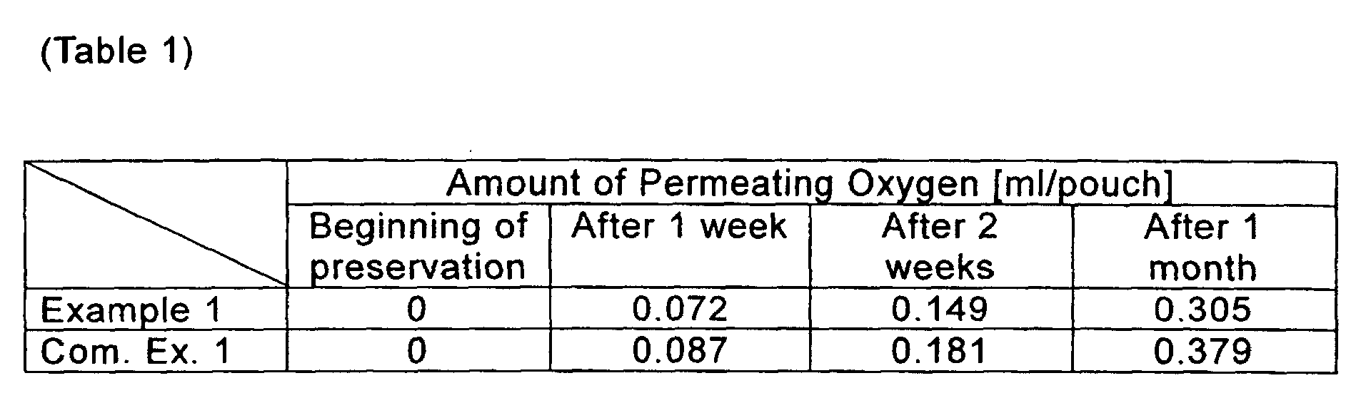
As apparent from Table 1, according to the spout of the present
invention, the amount of oxygen permeating into the pouch can be
minimized in comparison with that permeating into the pouch through the
boat-like portion of the conventional spout. While, in Example 1
described above, a gas barrier layer is not provided in the cylindrical
mouth part of the spout, the gas shielding capability of the spout can be
further improved by providing such a gas barrier layer.
According to the spout of the present invention, since the plastic
film constituting the pouch and the spout are brought into a smoother
contact with each other, it is possible to prevent wrinkles from being
caused upon the heat sealing, and to avoid stresses from being
concentrated on near a joined portion between the plastic film and the
spout. Hence, the heat sealing between the plastic pouch body and the
spout can be performed with higher reliability.
In addition, the spout of the present invention is able to prevent a
phenomenon that the film constituting the pouch body is bent to cause a
blockage inside the pouch at a position just below the spout when the
contents are poured from the pouch with the spout.
Further, merely by providing a cylindrical gas barrier layer in the
mouth part of the spout, it becomes possible to prevent gas permeation
through the spout itself, and to increase the gas shielding capability.
Additionally, the spout of the present invention can be simply
manufactured at a low cost without requiring complicated processes and
special materials.
In particular, when the spout of the present invention is applied to
a standing pouch, the pouch has a smoother outer appearance, a
standing posture of the pouch is noticeably improved, and a commodity
value of the pouch filled with the contents can be increased.
Claims (12)
- A spout for a pouch, comprising a tubular mouth part having a cap fitting portion and a seal part connected to a lower end portion of the mouth part for sealing with the pouch, wherein a horizontal cross-sectional shape of the seal part is different in a height direction between an upper end portion and a lower end portion thereof, and an outer peripheral length of the horizontal cross-sectional shape is substantially equal at any position between the upper end portion and the lower end portion of the seal part.
- A spout for a pouch according to Claim 1, wherein an area surrounded by a contour of the horizontal cross-section of the seal part continuously increases in a direction toward the lower end portion from the upper end portion of the seal part.
- A spout for a pouch according to Claim 1 or 2, wherein a horizontal cross-sectional shape of the seal part is circular or elliptic in the upper end portion thereof and is boat-like symmetrical in the left and right direction in the lower end portion thereof.
- A spout for a pouch according to any one of Claims 1 to 3, wherein wing pieces each having a thickness increasing in a direction toward the lower end portion from the upper end portion thereof are symmetrically provided on opposite sides of the seal part.
- A spout for a pouch according to any one of Claims 1 to 4, wherein outer-peripheral lower end portions of the seal part are rounded.
- A spout for a pouch according to any one of Claims 1 to 5, wherein a tongue-shaped projection is provided at a lower end portion of the seal part.
- A spout for a pouch according to any one of Claims 1 to 6, wherein a gas barrier layer is provided at least in the tubular mouth part of the spout.
- A spout for a pouch according to any one of Claims 1 to 7, wherein a bar-like member is provided to extend downward from the seal part.
- A spout for a pouch according to any one of Claims 1 to 8, wherein a rib is provided on the seal part.
- A spout for a pouch according to any one of Claims 1 to 9, wherein a cap equipped with a heat sealable lid is fitted to the mouth part of the spout, the cap having means to peel off the heat sealed lid from the mouth part of the spout when the cap is opened.
- A pouch with a spout, wherein a spout for a pouch according to any one of Claims 1 to 10 is fixed to the opening portion of the pouch by heat sealing.
- A pouch with a spout according to Claim 11, wherein the spout is fixed to the opening portion of the pouch such that the upper end portion of the heat- sealed part of the spout is arranged inward of the pouch from the upper end portion of the pouch body.
Applications Claiming Priority (3)
| Application Number | Priority Date | Filing Date | Title |
|---|---|---|---|
| JP2001299783 | 2001-09-28 | ||
| JP2001299783 | 2001-09-28 | ||
| PCT/JP2002/009273 WO2003029094A1 (en) | 2001-09-28 | 2002-09-11 | Spout for pouch and plastic pouch with spout fixed thereto |
Publications (2)
| Publication Number | Publication Date |
|---|---|
| EP1449784A1 true EP1449784A1 (en) | 2004-08-25 |
| EP1449784A4 EP1449784A4 (en) | 2009-09-23 |
Family
ID=19120472
Family Applications (1)
| Application Number | Title | Priority Date | Filing Date |
|---|---|---|---|
| EP02767946A Withdrawn EP1449784A4 (en) | 2001-09-28 | 2002-09-11 | Spout for pouch and plastic pouch with spout fixed thereto |
Country Status (5)
| Country | Link |
|---|---|
| US (1) | US20050040181A1 (en) |
| EP (1) | EP1449784A4 (en) |
| JP (1) | JP4345482B2 (en) |
| KR (1) | KR20040032870A (en) |
| WO (1) | WO2003029094A1 (en) |
Cited By (10)
| Publication number | Priority date | Publication date | Assignee | Title |
|---|---|---|---|---|
| EP1700794A1 (en) * | 2005-03-11 | 2006-09-13 | Georg Menshen GmbH + Co. KG | Plastic spout to be sealed to a pouch |
| EP1897815A2 (en) | 2006-09-05 | 2008-03-12 | Pöppelmann Holding GmbH & Co. KG. | Plastic pouring spout for film bags |
| FR2924691A1 (en) * | 2007-12-06 | 2009-06-12 | Oreal | Distribution head e.g. distribution bit, for container, has tubular shaped mounting apron defining smooth fixation surface for fixing flexible bag with average slope decreasing from median region of apron towards lateral ends of apron |
| US7762430B2 (en) * | 2002-12-23 | 2010-07-27 | Deutsche Sisi-Werke Gmbh & Co. Betriebs Kg | Closing element with outlet channel extending in funnel-like manner |
| WO2015062806A1 (en) | 2013-10-29 | 2015-05-07 | Cavonic GmbH | Plastic pourer (spout) for self-standing bag packs, self-standing bag pack and production method |
| WO2015125071A1 (en) * | 2014-02-24 | 2015-08-27 | Guala Pack S.P.A. | Oxygen impermeable spout for a flexible pouch |
| US9132944B2 (en) | 2011-01-11 | 2015-09-15 | Pöppelmann Holding GmbH & Co. KG | Spout and container having such a spout |
| EP2488423B1 (en) * | 2009-10-16 | 2016-03-30 | PPG Europe B.V. | Pouch containing a paint colourant composition |
| CN108461688A (en) * | 2018-03-20 | 2018-08-28 | 安徽天康(集团)股份有限公司 | Soft Roll lithium titanate battery automatic exhaust steam valve |
| WO2023196441A1 (en) * | 2022-04-05 | 2023-10-12 | Faulkner James D | Contaminant-resistant packaging |
Families Citing this family (40)
| Publication number | Priority date | Publication date | Assignee | Title |
|---|---|---|---|---|
| WO2004013008A1 (en) * | 2002-08-06 | 2004-02-12 | Toppan Printing Co.,Ltd | Spout, pouch equipped with spout and process for producing spout |
| JP4682569B2 (en) * | 2004-09-21 | 2011-05-11 | 凸版印刷株式会社 | Spout |
| KR101321328B1 (en) | 2006-03-06 | 2013-10-23 | 니혼 클로져 가부시키가이샤 | Composite spout and injection-forming apparatus for forming the composite spout |
| JP4848800B2 (en) * | 2006-03-06 | 2011-12-28 | 東洋製罐株式会社 | Composite spout and injection molding apparatus for forming composite spout |
| WO2007121437A2 (en) * | 2006-04-17 | 2007-10-25 | Ppi Technologies Global, Llc | Holder with integral gripper for transporting a flexible pouch during manufacturing |
| US7661560B2 (en) * | 2006-04-28 | 2010-02-16 | Pouch Pac Innovations, Llc | Flexible pouch with a tamper-evident outer cap fitment and method of forming |
| US8083102B2 (en) * | 2006-04-28 | 2011-12-27 | Pouch Pac Innovations, Llc | Flexible pouch with a tube spout fitment and flexible sleeve |
| US7584593B2 (en) * | 2006-11-01 | 2009-09-08 | Pouch Pac Innovations, Llc | Method and apparatus for opening a flexible pouch using opening fingers |
| WO2008067437A2 (en) * | 2006-11-29 | 2008-06-05 | Pouch Pac Innovations, Llc | System, method and machine for continuous loading of a product |
| US8562274B2 (en) | 2006-11-29 | 2013-10-22 | Pouch Pac Innovations, Llc | Load smart system for continuous loading of a pouch into a fill-seal machine |
| KR100831377B1 (en) * | 2007-10-22 | 2008-05-22 | 해성산업주식회사 | Eco-friendly multi-layered plastic bag and its manufacturing method |
| US9522773B2 (en) | 2009-07-09 | 2016-12-20 | Entegris, Inc. | Substantially rigid collapsible liner and flexible gusseted or non-gusseted liners and methods of manufacturing the same and methods for limiting choke-off in liners |
| US8468635B2 (en) * | 2009-11-25 | 2013-06-25 | Church & Dwight Co., Inc. | Surface treating device |
| USD624436S1 (en) | 2010-03-23 | 2010-09-28 | Justin Wojton | Packaging wrapper with cap |
| JP5643041B2 (en) * | 2010-09-28 | 2014-12-17 | 三笠産業株式会社 | Manufacturing method of pouring tool |
| TW201242670A (en) | 2010-11-23 | 2012-11-01 | Advanced Tech Materials | Liner-based dispenser |
| CN103648920B (en) | 2011-03-01 | 2016-10-05 | 高级技术材料公司 | Nested blow molded liner and overpack and method of manufacture |
| FR2984092B1 (en) * | 2011-12-16 | 2014-04-04 | Oreal | PACKAGING AND DISPENSING DEVICE |
| CA2885838C (en) * | 2012-10-02 | 2018-10-30 | Performance Packaging Of Nevada, Llc | Apparatus for oral delivery of fluids and semi-solid foods |
| JP6076072B2 (en) * | 2012-12-21 | 2017-02-08 | 大下産業株式会社 | Spout equipment and containers |
| USD712744S1 (en) | 2013-03-14 | 2014-09-09 | Silgan White Cap LLC | Closure |
| FR3008078B1 (en) * | 2013-07-08 | 2016-04-01 | Lablabo | DEVICE WITH RIGID CONTAINER AND FLEXIBLE CYLINDRICAL POCKET FOR PACKAGING FLUIDS. |
| US9309032B2 (en) | 2014-02-17 | 2016-04-12 | Silgan White Cap LLC | Dispenser and closure with hinge attached tamper band |
| USD756777S1 (en) | 2014-02-17 | 2016-05-24 | Silgan White Cap LLC | Closure |
| WO2015199085A1 (en) * | 2014-06-23 | 2015-12-30 | 株式会社細川洋行 | Spout for pouch, spout-attached pouch, and manufacturing method for spout for pouch |
| KR20170093784A (en) * | 2014-10-13 | 2017-08-16 | 롬 앤드 하아스 컴패니 | Pouched, water dispersible detergent formulations with high water content |
| JP6468799B2 (en) * | 2014-10-28 | 2019-02-13 | 三笠産業株式会社 | Pouch with spout |
| US9533802B2 (en) | 2014-10-31 | 2017-01-03 | Silgan White Cap LLC | Closure with tamper band and spout |
| USD760081S1 (en) | 2014-10-31 | 2016-06-28 | Silgan White Cap LLC | Spout |
| TWI688524B (en) * | 2015-03-17 | 2020-03-21 | 美商陶氏全球科技有限責任公司 | Flexible fitment for flexible container |
| WO2017135958A1 (en) | 2016-02-04 | 2017-08-10 | Silgan White Cap LLC | Container assembly with vent |
| US9938050B2 (en) | 2016-05-13 | 2018-04-10 | Silgan White Cap LLC | Closure with hinged tamper band |
| JP6926412B2 (en) * | 2016-08-08 | 2021-08-25 | 凸版印刷株式会社 | Pouch with spout |
| US10351315B2 (en) | 2017-09-19 | 2019-07-16 | Silgan White Cap LLC | Closure with tamper band and spout |
| JP7530712B2 (en) * | 2019-12-06 | 2024-08-08 | 株式会社細川洋行 | Discharge member with blocking member and storage container |
| US12263997B2 (en) * | 2021-03-16 | 2025-04-01 | Winpak Ltd. | Closure system with barrier layer |
| EP4384451A4 (en) * | 2021-08-09 | 2025-06-25 | Winpak Ltd. | MULTI-OPENING NON-SPILL POURING SPOUT |
| US12090711B2 (en) * | 2021-08-09 | 2024-09-17 | Ilc Dover Lp | Controlling a fluid flow |
| EP4173991B1 (en) | 2021-11-02 | 2025-12-03 | OP-Hygiene IP GmbH | Flexible mouth insert for pouch |
| US20230371749A1 (en) * | 2022-02-09 | 2023-11-23 | Jun Lu | Combination Condiment Shaker |
Family Cites Families (12)
| Publication number | Priority date | Publication date | Assignee | Title |
|---|---|---|---|---|
| US3260411A (en) * | 1964-07-13 | 1966-07-12 | American Can Co | Collapsible container structure |
| US4355742A (en) * | 1979-02-05 | 1982-10-26 | Scholle Corporation | Dispenser spigot for viscous material |
| US4732299A (en) * | 1986-02-10 | 1988-03-22 | Hoyt Earl E | Collapsible container |
| JPH0335049U (en) * | 1989-08-10 | 1991-04-05 | ||
| JPH0364229U (en) * | 1989-10-25 | 1991-06-24 | ||
| DE29509118U1 (en) * | 1995-06-02 | 1995-08-17 | Georg Menshen GmbH & Co KG, 57413 Finnentrop | Plastic pouring weld-in part for plastic containers |
| JPH111248A (en) * | 1997-04-07 | 1999-01-06 | Georg Menshen Gmbh & Co Kg | Container spout structure |
| JP4275240B2 (en) * | 1999-04-12 | 2009-06-10 | 株式会社フジシールインターナショナル | Container with dispensing tool |
| JP4382218B2 (en) * | 1999-10-29 | 2009-12-09 | 株式会社フジシールインターナショナル | How to close a pouch container with a spout |
| US6854614B2 (en) * | 1999-11-05 | 2005-02-15 | Rexam Medical Packaging, Inc. | Closure having an improved thread design |
| JP4641078B2 (en) * | 2000-02-01 | 2011-03-02 | 大日本印刷株式会社 | Pouring tool and packaging bag with pouring tool |
| US6273307B1 (en) * | 2000-08-17 | 2001-08-14 | Seaquist Closures Foreign, Inc. | Fitment for a pouch opening |
-
2002
- 2002-09-11 KR KR10-2004-7001284A patent/KR20040032870A/en not_active Ceased
- 2002-09-11 WO PCT/JP2002/009273 patent/WO2003029094A1/en not_active Ceased
- 2002-09-11 JP JP2003532371A patent/JP4345482B2/en not_active Expired - Fee Related
- 2002-09-11 EP EP02767946A patent/EP1449784A4/en not_active Withdrawn
- 2002-09-11 US US10/488,302 patent/US20050040181A1/en not_active Abandoned
Cited By (13)
| Publication number | Priority date | Publication date | Assignee | Title |
|---|---|---|---|---|
| US7762430B2 (en) * | 2002-12-23 | 2010-07-27 | Deutsche Sisi-Werke Gmbh & Co. Betriebs Kg | Closing element with outlet channel extending in funnel-like manner |
| EP1700794A1 (en) * | 2005-03-11 | 2006-09-13 | Georg Menshen GmbH + Co. KG | Plastic spout to be sealed to a pouch |
| RU2404097C2 (en) * | 2005-03-11 | 2010-11-20 | Георг Менсхен Гмбх Унд Ко.Кг | Part for reservoir discharging |
| EP1897815A2 (en) | 2006-09-05 | 2008-03-12 | Pöppelmann Holding GmbH & Co. KG. | Plastic pouring spout for film bags |
| EP1897815A3 (en) * | 2006-09-05 | 2011-06-01 | Pöppelmann Holding GmbH & Co. KG. | Plastic pouring spout for film bags |
| FR2924691A1 (en) * | 2007-12-06 | 2009-06-12 | Oreal | Distribution head e.g. distribution bit, for container, has tubular shaped mounting apron defining smooth fixation surface for fixing flexible bag with average slope decreasing from median region of apron towards lateral ends of apron |
| EP2488423B1 (en) * | 2009-10-16 | 2016-03-30 | PPG Europe B.V. | Pouch containing a paint colourant composition |
| US9132944B2 (en) | 2011-01-11 | 2015-09-15 | Pöppelmann Holding GmbH & Co. KG | Spout and container having such a spout |
| WO2015062806A1 (en) | 2013-10-29 | 2015-05-07 | Cavonic GmbH | Plastic pourer (spout) for self-standing bag packs, self-standing bag pack and production method |
| WO2015125071A1 (en) * | 2014-02-24 | 2015-08-27 | Guala Pack S.P.A. | Oxygen impermeable spout for a flexible pouch |
| US11046505B2 (en) | 2014-02-24 | 2021-06-29 | Guala Pack S.P.A. | Oxygen impermeable spout for a flexible pouch |
| CN108461688A (en) * | 2018-03-20 | 2018-08-28 | 安徽天康(集团)股份有限公司 | Soft Roll lithium titanate battery automatic exhaust steam valve |
| WO2023196441A1 (en) * | 2022-04-05 | 2023-10-12 | Faulkner James D | Contaminant-resistant packaging |
Also Published As
| Publication number | Publication date |
|---|---|
| WO2003029094A1 (en) | 2003-04-10 |
| JPWO2003029094A1 (en) | 2005-01-13 |
| JP4345482B2 (en) | 2009-10-14 |
| EP1449784A4 (en) | 2009-09-23 |
| KR20040032870A (en) | 2004-04-17 |
| US20050040181A1 (en) | 2005-02-24 |
Similar Documents
| Publication | Publication Date | Title |
|---|---|---|
| US20050040181A1 (en) | Spout for pouch and plastic pouch with spout fixed thereto | |
| JP5401369B2 (en) | Self-supporting bag, manufacturing method thereof, and self-supporting bag with contents | |
| US7588157B2 (en) | In-mold label system plastic container | |
| JP3815866B2 (en) | Plastic pouch | |
| US10968020B2 (en) | Self-standing bag and method for manufacturing the same | |
| JP4641078B2 (en) | Pouring tool and packaging bag with pouring tool | |
| JP2000153849A (en) | Flat bottom bag and manufacturing method thereof | |
| JP4220044B2 (en) | Injection mold container for microwave oven | |
| JPH1129156A (en) | Pouch with spout having straw and reinforcement function | |
| JP4270621B2 (en) | Retort injection molded container | |
| JP4848804B2 (en) | Multi-chamber pouch filling method | |
| JPH1159702A (en) | Pouch with spout | |
| JP2002002736A (en) | Outlet union | |
| JPH1191798A (en) | Oblique seal bag container with spout | |
| JP2005206163A (en) | Mouth bag | |
| JP4942885B2 (en) | Easy-open bag | |
| JP2002002737A (en) | Outlet union | |
| JPH11171250A (en) | Sealed plastic container that can be opened and closed repeatedly | |
| JP7229320B2 (en) | freestanding bag | |
| JP2002002722A (en) | Pouch | |
| JP4802390B2 (en) | bag | |
| JP2002068217A (en) | Branch type pouch with handle | |
| JPH05139463A (en) | Sealed package | |
| JP2510801Y2 (en) | Packaging bag | |
| JP2001114304A (en) | Pouch with spout fitted with portable cord |
Legal Events
| Date | Code | Title | Description |
|---|---|---|---|
| PUAI | Public reference made under article 153(3) epc to a published international application that has entered the european phase |
Free format text: ORIGINAL CODE: 0009012 |
|
| 17P | Request for examination filed |
Effective date: 20040427 |
|
| AK | Designated contracting states |
Kind code of ref document: A1 Designated state(s): AT BE CH CY DE DK ES FI FR GB GR IE IT LI LU MC NL PT SE TR |
|
| A4 | Supplementary search report drawn up and despatched |
Effective date: 20090826 |
|
| 17Q | First examination report despatched |
Effective date: 20100301 |
|
| STAA | Information on the status of an ep patent application or granted ep patent |
Free format text: STATUS: THE APPLICATION IS DEEMED TO BE WITHDRAWN |
|
| 18D | Application deemed to be withdrawn |
Effective date: 20100713 |