EP1449683A2 - Transmitter mounting structure for tire condition monitoring apparatus - Google Patents
Transmitter mounting structure for tire condition monitoring apparatus Download PDFInfo
- Publication number
- EP1449683A2 EP1449683A2 EP03026638A EP03026638A EP1449683A2 EP 1449683 A2 EP1449683 A2 EP 1449683A2 EP 03026638 A EP03026638 A EP 03026638A EP 03026638 A EP03026638 A EP 03026638A EP 1449683 A2 EP1449683 A2 EP 1449683A2
- Authority
- EP
- European Patent Office
- Prior art keywords
- valve stem
- wheel
- casing
- coupling fixture
- mounting structure
- Prior art date
- Legal status (The legal status is an assumption and is not a legal conclusion. Google has not performed a legal analysis and makes no representation as to the accuracy of the status listed.)
- Granted
Links
- 238000012544 monitoring process Methods 0.000 title claims abstract description 16
- 230000008878 coupling Effects 0.000 claims abstract description 46
- 238000010168 coupling process Methods 0.000 claims abstract description 46
- 238000005859 coupling reaction Methods 0.000 claims abstract description 46
- 238000004873 anchoring Methods 0.000 claims abstract description 5
- 230000001105 regulatory effect Effects 0.000 claims description 24
- 238000000034 method Methods 0.000 claims description 8
- 238000010586 diagram Methods 0.000 description 2
- 238000004519 manufacturing process Methods 0.000 description 2
- 239000002184 metal Substances 0.000 description 2
- 239000011324 bead Substances 0.000 description 1
- 238000005452 bending Methods 0.000 description 1
- 230000007423 decrease Effects 0.000 description 1
- 238000005259 measurement Methods 0.000 description 1
- 230000035945 sensitivity Effects 0.000 description 1
- 230000000007 visual effect Effects 0.000 description 1
Images


Classifications
-
- B—PERFORMING OPERATIONS; TRANSPORTING
- B60—VEHICLES IN GENERAL
- B60C—VEHICLE TYRES; TYRE INFLATION; TYRE CHANGING; CONNECTING VALVES TO INFLATABLE ELASTIC BODIES IN GENERAL; DEVICES OR ARRANGEMENTS RELATED TO TYRES
- B60C23/00—Devices for measuring, signalling, controlling, or distributing tyre pressure or temperature, specially adapted for mounting on vehicles; Arrangement of tyre inflating devices on vehicles, e.g. of pumps or of tanks; Tyre cooling arrangements
- B60C23/02—Signalling devices actuated by tyre pressure
- B60C23/04—Signalling devices actuated by tyre pressure mounted on the wheel or tyre
- B60C23/0491—Constructional details of means for attaching the control device
- B60C23/0494—Valve stem attachments positioned inside the tyre chamber
-
- B—PERFORMING OPERATIONS; TRANSPORTING
- B60—VEHICLES IN GENERAL
- B60C—VEHICLE TYRES; TYRE INFLATION; TYRE CHANGING; CONNECTING VALVES TO INFLATABLE ELASTIC BODIES IN GENERAL; DEVICES OR ARRANGEMENTS RELATED TO TYRES
- B60C23/00—Devices for measuring, signalling, controlling, or distributing tyre pressure or temperature, specially adapted for mounting on vehicles; Arrangement of tyre inflating devices on vehicles, e.g. of pumps or of tanks; Tyre cooling arrangements
- B60C23/02—Signalling devices actuated by tyre pressure
- B60C23/04—Signalling devices actuated by tyre pressure mounted on the wheel or tyre
- B60C23/0408—Signalling devices actuated by tyre pressure mounted on the wheel or tyre transmitting the signals by non-mechanical means from the wheel or tyre to a vehicle body mounted receiver
Definitions
- the present invention relates to a transmitter mounting structure for a tire condition monitoring apparatus, and more specifically, to a transmitter mounting structure for a wireless type tire condition monitoring apparatus enabling tire conditions, such as tire air pressure, to be checked from the passenger compartment of a vehicle.
- a transmitter for a tire air pressure monitoring apparatus is mounted on a wheel and located in a tire.
- a mounting structure of the transmitter includes a valve stem, a spring element, and an electronic module for measuring the air pressure of the tire and transmitting the measured air pressure.
- the valve stem is coupled to the spring element.
- the spring element has a clamp plate coupled to the electronic module. The clamp plate clamps the electronic module to the wheel. When the wheel is rotating, various forces, such as centrifugal force, act upon the electronic module. The elastic force of the spring element acts to effectively suppress or control the movement of the electronic module. Accordingly, the electronic module is pressed against a drop center of the wheel when mounted on the wheel (refer to United States Patent No. 5,956,820).
- One aspect of the present invention is a mounting structure for a transmitter of a tire condition monitoring apparatus arranged in a tire of a vehicle having a wheel.
- the wheel including a drop center and a rim formed integrally with the drop center at a predetermined angle relative to the drop center.
- the mounting structure includes a valve stem attachable to the rim of the wheel for charging air into the tire.
- the valve stem has a basal end.
- the mounting structure further includes a casing connected to the valve stem to house the transmitter and a coupling fixture for coupling the casing and the valve stem.
- the coupling fixture includes a coupler coupled to the basal end of the valve stem, an anchor for anchoring the casing and a connection for connecting the coupler and the anchor at an angle to one another so that the coupling fixture is resilient. The angle between the coupler and the anchor is greater than the predetermined angle before the coupling fixture couples the casing and the valve stem to one another.
- Another aspect of the present invention is a method of mounting a transmitter of a tire condition monitoring apparatus arranged in a tire of a vehicle having a wheel.
- the wheel includes a drop center and a rim formed integrally with the drop center at a predetermined angle relative to the drop center.
- the rim has a valve hole.
- the method includes preparing a valve stem for charging air into a tire, the valve stem having a basal end, preparing a casing for housing the transmitter, the casing having a projection, preparing a coupling fixture for coupling the casing and the valve stem, the coupling fixture including a coupler coupled to the basal end of the valve stem and having a coupling hole, an anchor for anchoring the casing, and a connection for connecting the coupler and the anchor at an angle to one another so that the coupling fixture is resilient, with the angle between the coupler and the anchor being greater than the predetermined angle before the coupling fixture couples the casing and the valve stem, attaching the casing to the anchor of the coupler, inserting the basal end of the valve stem through a coupling hole of the coupling fixture to couple the basal end of the valve stem to the coupling fixture with a bushing, and attaching the valve stem to the valve hole in the rim when the projection of the casing is abutted against the drop center of the wheel by the resiliency of the
- Fig. 1 is a schematic diagram of a tire condition monitoring apparatus, which includes a transmitter mounting structure according to a preferred embodiment of the present invention. As shown in Fig. 1, the tire condition monitoring apparatus 1 includes four transmitters 30, each arranged in each tire 20 of a vehicle 10, and a receiver 40 arranged in the body 11 of the vehicle 10.
- Each transmitter 30 is fixed to the interior of the corresponding tire 20, for example, to the wheel 21 of the tire 20.
- the transmitter 30 measures conditions of the tire 20, such as the tire pressure in the corresponding tire 20, and transmits the data including the tire pressure data obtained through the measurement in a wireless manner.
- the receiver 40 is located at a predetermined position on the body 11 and operated, for example, by electric power from a vehicle battery (not shown).
- the receiver 40 has a receiving antenna 41, which is connected to the receiver 40 by a cable 42.
- the receiver 40 receives data transmitted from each transmitter 30 through the receiving antenna 41.
- a display 50 is arranged within the visual range of the driver of the vehicle 10 in the vehicle compartment.
- the display 50 is connected to the receiver 40 by a cable 43.
- a connection concavity 61 is formed along the circumferential direction at the basal end of a valve stem 60, which is arranged in the tire 20.
- a rubber grommet 62 is fitted in the connection concavity 61.
- the rubber grommet 62 is pressed against the wall defining a valve hole 22 extending through the wheel 21.
- a valve nut 63 is engaged with the valve stem 60 from the outer side of the wheel 21 to fasten the valve stem 60 to the wheel 21.
- the rubber grommet 62 hermetically seals the tire 20.
- a plate spring (coupling fixture) 70 is connected to the basal end of the valve stem 60.
- a bushing 64 is press-fitted into the basal end of the valve stem 60 to connect the valve stem 60 and the plate spring 70.
- a casing 80 which houses the transmitter 30, and a bracket 90 are attached to the plate spring 70.
- a projection 81 extends from the bottom surface of the casing 80. The resiliency of the plate spring 70 abuts the projection 81 against a drop center 23 of the wheel 21.
- side walls 64a extend from opposite sides of the bushing 64.
- a through hole 64b extends through the center of the bushing 64. Air is charged into the tire from the valve stem 60 and through the through hole 64b.
- a valve cap 65 is engaged with the distal end of the valve stem 60.
- the plate spring 70 is resilient and formed, for example, by bending a thin metal piece until its cross section becomes U-shaped.
- the plate spring 70 includes a coupler 73 coupled to the basal end of the valve stem 60.
- a coupling hole 71 extends through the coupler 73.
- the plate spring 70 also includes an anchor 74, which is anchored to the casing 80, and a connection 75, which connects the coupler 73 and the anchor 74.
- Two anchor holes 72 extend through the anchor 74.
- the connection 75 connects the coupler 73 and the anchor 74 so that the plate spring 70 is resilient. More specifically, the connection 75 is bent so as to have a predetermined curvature R, as shown in Fig. 4(b).
- the angle ⁇ 2 formed between the coupler 73 and the anchor 74 before the plate spring 70 is attached to the valve stem 60 is greater than the angle ⁇ 1 formed between the coupler 73 and the anchor 74 after the plate spring 70.
- the reason for this is to cope with the various cross sectional shapes a wheel 21 may have.
- the plate spring 70 may be employed even when the rim angle (second predetermined angle) ⁇ r formed between a drop center 23 of the wheel 21 and a rim 24 of the wheel 21 is larger than angle ⁇ 1 (first predetermined angle), as shown in Fig. 6. More specifically, before the plate spring 70 is attached to the valve stem 60, the angle ⁇ 2 formed between the coupler 73 and the anchor 74 is set so as to be greater than the angle ⁇ 1 and the angle ⁇ r.
- a bracket 90 is provided with two rotation regulating walls 91 for regulating the rotation of the plate spring 70.
- the rotation regulating walls 91 abut against the side walls 64a of the bushing 64 when the valve stem 60 is inserted through the valve hole 22.
- the two rotation regulating walls 91 are formed so as to sandwich the side walls 64a of the bushing 64.
- Two anchor holes 92 extend through the bracket 90. The anchor holes 92 correspond to the two anchor holes 72 of the plate spring 70.
- two protrusions 82 extend from the top surface of the casing 80.
- the protrusions 82 project through the anchor holes 92 of the bracket 90 and the anchor holes 72 of the plate spring 70.
- the projected part of each protrusion 82 is heated and deformed into a rivet shape. This fixes the casing 80 to the plate spring 70 and the bracket 90.
- the valve stem 60 is inserted through the valve hole 22 from the inner side of the wheel 21. Then, the valve nut 63 is threadably engaged with the valve stem 60 from the outer side of the wheel 21 to attach the valve stem 60 to the wheel 21.
- the plate spring 70 which is coupled to the basal end of the valve stem 60, tends to rotate in the turning direction of the valve nut 63 when threading the valve nut 63 on to the valve stem 60.
- the side walls 64a of the bushing 64 which is pressed fitted into the basal end of the valve stem 60, abuts against the rotation regulating walls 91 of the bracket 90.
- the bracket 90 is fixed to the plate spring 70 by the pair of protrusions 82 of the casing 80.
- the projection 81 extending from the bottom surface of the casing 80 is abutted against the drop center of the wheel 21 by the resiliency of the plate spring 70. Therefore, the side walls 64a of the bushing 64 abuts against the rotation regulating walls 91 and regulates the rotation of the plate spring 70 even when the plate spring 70 tends to rotate in the rotation direction of the valve nut 63 when screwing the valve nut 63 on to the valve stem 60. As a result, the plate spring 70 does not rotate in the rotation direction of the valve nut 63 when the valve nut 63 is threaded on to the valve stem 60. Accordingly, the valve stem 60 is attached to the wheel 21 in a state in which the projection 81 of the casing 80 is abutted against the drop center 23 of the wheel 21.
- Centrifugal force acts on the casing 80 when the vehicle 10 is moving.
- the centrifugal force increases in proportion to the velocity of the vehicle 10. Therefore, when the velocity of the vehicle 10 reaches a first velocity (for example, 40 km/h), the centrifugal force becomes greater than the resiliency of the plate spring 70.
- a first velocity for example, 40 km/h
- the centrifugal force becomes greater than the resiliency of the plate spring 70.
- the projection 81 of the casing 80 moves away from the drop center 23 of the wheel 21.
- the projection 81 of the casing 80 When the vehicle 10 is not moving or when changing the tire 20, the projection 81 of the casing 80 is abutted against the drop center 23 of the wheel 21. Thus, when changing the tire 20, the bead of the tire 20 does not hit the bracket 90. This prevents the casing 80, which houses the transmitter 30, from being damaged.
- the projection 81 of the casing 80 When the vehicle is moving at a velocity that is greater than or equal to the first velocity, the projection 81 of the casing 80 is moved away from the drop center 23 of the wheel 21. This lessens the influence of the wheel 21 on radio waves transmitted from the transmitter 30. That is, since the casing 80 which houses the transmitter 30 becomes more distant from the wheel 21, which is generally formed of metal, the radio waves transmitted from the transmitter 30 are less affected by the wheel 21.
- the reception sensitivity of the receiver 40 improves when the vehicle is moving at a velocity that is greater than or equal to the first speed. Accordingly, the receipt of data transmitted from the transmitter 30 by the receiver 40 through the receiving antenna 41 is
- the transmitter mounting structure for a tire condition monitoring apparatus of the present embodiment has the advantages described below.
- the relationship between the bushing 64, which is provided with the side walls 64a and press fitted to the basal end of the valve stem 60, and the regulating walls 91, which extend from the bracket 90, may be reversed. That is, the rotation regulating walls may be formed on the bushing 64, and side walls corresponding to the rotation regulating walls may be formed on the bracket 90.
- the present invention may be embodied in any type of vehicle that uses a tire 20, such as a four-wheeled vehicle, a two-wheeled vehicle, a bus, or a truck.
Landscapes
- Engineering & Computer Science (AREA)
- Mechanical Engineering (AREA)
- Measuring Fluid Pressure (AREA)
Abstract
Description
- The present invention relates to a transmitter mounting structure for a tire condition monitoring apparatus, and more specifically, to a transmitter mounting structure for a wireless type tire condition monitoring apparatus enabling tire conditions, such as tire air pressure, to be checked from the passenger compartment of a vehicle.
- A transmitter for a tire air pressure monitoring apparatus is mounted on a wheel and located in a tire. A mounting structure of the transmitter includes a valve stem, a spring element, and an electronic module for measuring the air pressure of the tire and transmitting the measured air pressure. The valve stem is coupled to the spring element. The spring element has a clamp plate coupled to the electronic module. The clamp plate clamps the electronic module to the wheel. When the wheel is rotating, various forces, such as centrifugal force, act upon the electronic module. The elastic force of the spring element acts to effectively suppress or control the movement of the electronic module. Accordingly, the electronic module is pressed against a drop center of the wheel when mounted on the wheel (refer to United States Patent No. 5,956,820).
- The fastening device described in United States Patent No. 5,956,820, however, cannot cope with all the cross sectional shapes of wheels. That is, there are many types of wheels with different cross sectional shapes, such as, wheels with a drop-center rim, a shallow base rim, a broad flat-base rim, and a broad deep rim. Therefore, the valve stem and the casing which houses the transmitter, and ultimately the mounting angle of the electronic module, is unambiguously determined by the cross sectional shape of the wheel. As a result, in order to mount the electronic module in a state pressed against the drop center of the wheel, the spring element and clamp plate must be in correspondence to the cross sectional shape of the wheel.
- One aspect of the present invention is a mounting structure for a transmitter of a tire condition monitoring apparatus arranged in a tire of a vehicle having a wheel. The wheel including a drop center and a rim formed integrally with the drop center at a predetermined angle relative to the drop center. The mounting structure includes a valve stem attachable to the rim of the wheel for charging air into the tire. The valve stem has a basal end. The mounting structure further includes a casing connected to the valve stem to house the transmitter and a coupling fixture for coupling the casing and the valve stem. The coupling fixture includes a coupler coupled to the basal end of the valve stem, an anchor for anchoring the casing and a connection for connecting the coupler and the anchor at an angle to one another so that the coupling fixture is resilient. The angle between the coupler and the anchor is greater than the predetermined angle before the coupling fixture couples the casing and the valve stem to one another.
- Another aspect of the present invention is a method of mounting a transmitter of a tire condition monitoring apparatus arranged in a tire of a vehicle having a wheel. The wheel includes a drop center and a rim formed integrally with the drop center at a predetermined angle relative to the drop center. The rim has a valve hole. The method includes preparing a valve stem for charging air into a tire, the valve stem having a basal end, preparing a casing for housing the transmitter, the casing having a projection, preparing a coupling fixture for coupling the casing and the valve stem, the coupling fixture including a coupler coupled to the basal end of the valve stem and having a coupling hole, an anchor for anchoring the casing, and a connection for connecting the coupler and the anchor at an angle to one another so that the coupling fixture is resilient, with the angle between the coupler and the anchor being greater than the predetermined angle before the coupling fixture couples the casing and the valve stem, attaching the casing to the anchor of the coupler, inserting the basal end of the valve stem through a coupling hole of the coupling fixture to couple the basal end of the valve stem to the coupling fixture with a bushing, and attaching the valve stem to the valve hole in the rim when the projection of the casing is abutted against the drop center of the wheel by the resiliency of the coupling fixture.
- The invention and preferred objects and advantages thereof, may best be understood by reference to the following description of the certain exemplifying embodiments together with the accompanying drawings in which:
- Fig. 1 is a schematic block diagram showing the structure of a tire condition monitoring apparatus according to a preferred embodiment of the present invention;
- Fig. 2 is a cross sectional view of a transmitter mounting structure for the tire condition monitoring apparatus in the preferred embodiment of the present invention;
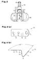
- Fig. 3 is a plan view of the transmitter of the tire condition monitoring apparatus of Fig. 2;
- Fig. 4(a) is a plan view showing a plate spring used in the mounting structure of Fig. 2, and Fig. 4(b) is a cross sectional view of the plate spring of Fig. 4(a);
- Fig. 5 is a perspective view showing a bracket used in the mounting structure of Fig. 2;
- Fig. 6 is a cross sectional view showing the state of a casing for the transmitter mounting structure of the tire condition monitoring apparatus when the vehicle velocity is less than a first speed; and
- Fig. 7 is a cross sectional view showing the state of the casing of Fig. 6 when the vehicle velocity is greater than or equal to a second speed.
-
- In the drawings, like numerals are used for like elements throughout.
- Fig. 1 is a schematic diagram of a tire condition monitoring apparatus, which includes a transmitter mounting structure according to a preferred embodiment of the present invention. As shown in Fig. 1, the tire
condition monitoring apparatus 1 includes fourtransmitters 30, each arranged in eachtire 20 of avehicle 10, and areceiver 40 arranged in thebody 11 of thevehicle 10. - Each
transmitter 30 is fixed to the interior of thecorresponding tire 20, for example, to thewheel 21 of thetire 20. Thetransmitter 30 measures conditions of thetire 20, such as the tire pressure in thecorresponding tire 20, and transmits the data including the tire pressure data obtained through the measurement in a wireless manner. - The
receiver 40 is located at a predetermined position on thebody 11 and operated, for example, by electric power from a vehicle battery (not shown). Thereceiver 40 has a receiving antenna 41, which is connected to thereceiver 40 by acable 42. Thereceiver 40 receives data transmitted from eachtransmitter 30 through the receiving antenna 41. Adisplay 50 is arranged within the visual range of the driver of thevehicle 10 in the vehicle compartment. Thedisplay 50 is connected to thereceiver 40 by acable 43. - As shown in Fig. 2, a
connection concavity 61 is formed along the circumferential direction at the basal end of avalve stem 60, which is arranged in thetire 20. Arubber grommet 62 is fitted in theconnection concavity 61. Therubber grommet 62 is pressed against the wall defining avalve hole 22 extending through thewheel 21. Avalve nut 63 is engaged with thevalve stem 60 from the outer side of thewheel 21 to fasten thevalve stem 60 to thewheel 21. As a result, the rubber grommet 62 hermetically seals thetire 20. - A plate spring (coupling fixture) 70 is connected to the basal end of the
valve stem 60. Abushing 64 is press-fitted into the basal end of thevalve stem 60 to connect thevalve stem 60 and theplate spring 70. Acasing 80, which houses thetransmitter 30, and abracket 90 are attached to theplate spring 70. Aprojection 81 extends from the bottom surface of thecasing 80. The resiliency of theplate spring 70 abuts theprojection 81 against adrop center 23 of thewheel 21. - As shown in Fig. 3,
side walls 64a extend from opposite sides of thebushing 64. A throughhole 64b extends through the center of thebushing 64. Air is charged into the tire from thevalve stem 60 and through the throughhole 64b. Avalve cap 65 is engaged with the distal end of thevalve stem 60. - Referring to Figs. 4(a) and 4(b), the
plate spring 70 is resilient and formed, for example, by bending a thin metal piece until its cross section becomes U-shaped. Theplate spring 70 includes acoupler 73 coupled to the basal end of thevalve stem 60. Acoupling hole 71 extends through thecoupler 73. Theplate spring 70 also includes ananchor 74, which is anchored to thecasing 80, and aconnection 75, which connects thecoupler 73 and theanchor 74. Twoanchor holes 72 extend through theanchor 74. Theconnection 75 connects thecoupler 73 and theanchor 74 so that theplate spring 70 is resilient. More specifically, theconnection 75 is bent so as to have a predetermined curvature R, as shown in Fig. 4(b). - As show in Fig. 4(b), the angle 2 formed between the
coupler 73 and theanchor 74 before theplate spring 70 is attached to thevalve stem 60 is greater than the angle 1 formed between thecoupler 73 and theanchor 74 after theplate spring 70. The reason for this is to cope with the various cross sectional shapes awheel 21 may have. For example, theplate spring 70 may be employed even when the rim angle (second predetermined angle) r formed between adrop center 23 of thewheel 21 and arim 24 of thewheel 21 is larger than angle 1 (first predetermined angle), as shown in Fig. 6. More specifically, before theplate spring 70 is attached to thevalve stem 60, the angle 2 formed between thecoupler 73 and theanchor 74 is set so as to be greater than the angle 1 and the angle r. - As shown in Fig. 5, a
bracket 90 is provided with tworotation regulating walls 91 for regulating the rotation of theplate spring 70. Therotation regulating walls 91 abut against theside walls 64a of thebushing 64 when thevalve stem 60 is inserted through thevalve hole 22. As shown in Fig. 3, the tworotation regulating walls 91 are formed so as to sandwich theside walls 64a of thebushing 64. Two anchor holes 92 extend through thebracket 90. The anchor holes 92 correspond to the two anchor holes 72 of theplate spring 70. - As shown in Fig. 2, two
protrusions 82 extend from the top surface of thecasing 80. Theprotrusions 82 project through the anchor holes 92 of thebracket 90 and the anchor holes 72 of theplate spring 70. The projected part of eachprotrusion 82 is heated and deformed into a rivet shape. This fixes thecasing 80 to theplate spring 70 and thebracket 90. - A method for arranging the
valve stem 60 in thevalve hole 22 of thewheel 21 will now be described. - As shown in Fig. 6, when the
casing 80 is fixed to theplate spring 70 and thebracket 90, thebushing 64 is inserted through thecoupling hole 71 of theplate spring 70. Then, thebushing 64 is press fitted to the basal end of thevalve stem 60 to connect the basal end of thevalve stem 60 to theplate spring 70. - Subsequently, in a state in which the
valve nut 63 and thecap 65 are removed, thevalve stem 60 is inserted through thevalve hole 22 from the inner side of thewheel 21. Then, thevalve nut 63 is threadably engaged with the valve stem 60 from the outer side of thewheel 21 to attach thevalve stem 60 to thewheel 21. At this time, theplate spring 70, which is coupled to the basal end of thevalve stem 60, tends to rotate in the turning direction of thevalve nut 63 when threading thevalve nut 63 on to thevalve stem 60. However, as shown in Fig. 3, theside walls 64a of thebushing 64, which is pressed fitted into the basal end of thevalve stem 60, abuts against therotation regulating walls 91 of thebracket 90. Further, as shown in Fig. 6, thebracket 90 is fixed to theplate spring 70 by the pair ofprotrusions 82 of thecasing 80. - The
projection 81 extending from the bottom surface of thecasing 80 is abutted against the drop center of thewheel 21 by the resiliency of theplate spring 70. Therefore, theside walls 64a of thebushing 64 abuts against therotation regulating walls 91 and regulates the rotation of theplate spring 70 even when theplate spring 70 tends to rotate in the rotation direction of thevalve nut 63 when screwing thevalve nut 63 on to thevalve stem 60. As a result, theplate spring 70 does not rotate in the rotation direction of thevalve nut 63 when thevalve nut 63 is threaded on to thevalve stem 60. Accordingly, thevalve stem 60 is attached to thewheel 21 in a state in which theprojection 81 of thecasing 80 is abutted against thedrop center 23 of thewheel 21. - Centrifugal force acts on the
casing 80 when thevehicle 10 is moving. The centrifugal force increases in proportion to the velocity of thevehicle 10. Therefore, when the velocity of thevehicle 10 reaches a first velocity (for example, 40 km/h), the centrifugal force becomes greater than the resiliency of theplate spring 70. As a result, when thevehicle 10 is moving at the first velocity or faster, theprojection 81 of thecasing 80 moves away from thedrop center 23 of thewheel 21. - When the
vehicle 10 reaches a second velocity (for example, 80 km/h), which is greater than the first speed,distal portions 91a of therotation regulating walls 91 abut against thecoupler 73 of theplate spring 70, as shown in Fig. 7. This restricts further movement of thecasing 80 from thedrop center 23 of thewheel 21 even when the velocity becomes greater than the second speed. As a result, the resiliency of theplate spring 70 is maintained. When the velocity of thevehicle 10 becomes less than the first velocity, theprojection 81 of thecasing 80 abuts against thedrop center 23 of thewheel 21 again, as shown in Fig. 6. - When the
vehicle 10 is not moving or when changing thetire 20, theprojection 81 of thecasing 80 is abutted against thedrop center 23 of thewheel 21. Thus, when changing thetire 20, the bead of thetire 20 does not hit thebracket 90. This prevents thecasing 80, which houses thetransmitter 30, from being damaged. When the vehicle is moving at a velocity that is greater than or equal to the first velocity, theprojection 81 of thecasing 80 is moved away from thedrop center 23 of thewheel 21. This lessens the influence of thewheel 21 on radio waves transmitted from thetransmitter 30. That is, since thecasing 80 which houses thetransmitter 30 becomes more distant from thewheel 21, which is generally formed of metal, the radio waves transmitted from thetransmitter 30 are less affected by thewheel 21. Thus, the reception sensitivity of thereceiver 40 improves when the vehicle is moving at a velocity that is greater than or equal to the first speed. Accordingly, the receipt of data transmitted from thetransmitter 30 by thereceiver 40 through the receiving antenna 41 is ensured. - The transmitter mounting structure for a tire condition monitoring apparatus of the present embodiment has the advantages described below.
- (1) The angle 2 (refer to Fig. 4(b)) formed by the
coupler 73 and theanchor 74 of theplate spring 70 before theplate spring 70 is attached to thevalve stem 60 is set so as to be greater than the maximum rim angle r (refer to Fig. 6) formed between thedrop center 23 of thewheel 21 and therim 24 of thewheel 21. Therefore, when thevalve stem 60 coupled to theplate spring 70 is attached to thewheel 21, theprojection 81 of thecasing 80 is abutted against thedrop center 23 of thewheel 21. Accordingly, thetransmitter 30 may be attached to thewheel 21 regardless of the cross sectional shape of thewheel 21. Thus, when thecasing 80 is abutted against thedrop center 23 of thewheel 21, thevalve stem 60 is attached to thewheel 21 regardless of the cross sectional shape of thewheel 21. - (2) The two
rotation regulating walls 91 extending from thebracket 90 abut against theside walls 64a of thebushing 64 when thevalve stem 60 is arranged in thevalve hole 22 of thewheel 21 to regulate the rotation of theplate spring 70. Theside walls 64a of thebushing 64 are located between the tworotation regulating walls 91 to abut against therotation regulating walls 91. Therefore, the rotation of theplate spring 70 is regulated even when theplate spring 70 tends to rotate in the rotation direction of thevalve nut 63 when threading on thevalve nut 63 on thevalve stem 60. As a result, theplate spring 70 does not rotate in the rotation direction of thevalve nut 63 when thevalve nut 63 is threaded on to thevalve stem 60. Accordingly, the abutment of theprojection 81 of thecasing 80 against thedrop center 23 of thewheel 21 enables the attachment of thevalve stem 60. - (3) When the velocity of the
vehicle 10 attains a second velocity (for example, 80 km/h) greater than the first velocity (for example, 40 km/h), thedistal portions 91a of therotation regulating walls 91 abut against thecoupler 73 of theplate spring 70, as shown in Fig. 7. Therefore, thecasing 80 does not separate from thedrop center 23 of thewheel 21 even when the vehicle moves at a velocity greater than the second speed. As a result, the elastic return force of theplate spring 70 is maintained. When the velocity of thevehicle 10 decreases to below the first speed, theprojection 81 of thecasing 80 abuts thedrop center 23 of thewheel 21. - (4) Since the electronic module (casing 80) is arranged
in a state pressed against the drop center of the
wheel 21, a spring element and a clamp plate conforming to the cross sectional shape of a wheel, as described in United States Patent No. 5,956,820, are unnecessary. This reduces the number of parts and facilitates the management of such parts when manufacturing the device. Accordingly, parts are assembled together more efficiently and manufacturing efficiency is improved. -
- It should be apparent to those skilled in the art that the present invention may be embodied in many other specific forms. Particularly, it should be understood that the invention may be embodied in the following forms.
- The relationship between the
bushing 64, which is provided with theside walls 64a and press fitted to the basal end of thevalve stem 60, and the regulatingwalls 91, which extend from thebracket 90, may be reversed. That is, the rotation regulating walls may be formed on thebushing 64, and side walls corresponding to the rotation regulating walls may be formed on thebracket 90. - The present invention may be embodied in any type of vehicle that uses a
tire 20, such as a four-wheeled vehicle, a two-wheeled vehicle, a bus, or a truck. - The present examples and embodiments are to be considered as illustrative and not restrictive.
Claims (13)
- A mounting structure for a transmitter of a tire condition monitoring apparatus arranged in a tire of a vehicle having a wheel and the wheel including a drop center and a rim formed integrally with the drop center at a predetermined angle relative to the drop center, the mounting structure including a valve stem (60) attachable to the rim of the wheel for charging air into the tire, the valve stem having a basal end, a casing (80) connected to the valve stem to house the transmitter, and a coupling fixture (70) for coupling the casing and the valve stem, the mounting structure being characterized in that the coupling fixture including:a coupler (73) coupled to the basal end of the valve stem;an anchor (74) for anchoring the casing; anda connection (75) for connecting the coupler and the anchor at an angle (2) to one another so that the coupling fixture is resilient, with the angle between the coupler and the anchor being greater than the predetermined angle before the coupling fixture couples the casing and the valve stem to one another.
- The transmitter mounting structure according to claim 1, characterized in that the wheel is a first or second wheel with the rim of each of the first or second wheels formed at first and second predetermined angles, respectively, relative to the drop center of each wheel, and the angle between the coupler and the anchor is set so as to be greater than the first and second predetermined angles before the coupling fixture couples the casing and the valve stem.
- The transmitter mounting structure according to claim 1 or 2, further characterized by:a valve nut (63) for attaching the valve stem to the wheel, anda regulating unit (64, 90) for regulating the rotation of the coupling fixture when the valve nut is attached to the valve stem.
- The transmitter mounting structure according to claim 3, characterized in that the regulating unit includes:a bushing (64) that is press fitted to the basal end of the valve stem; anda bracket (90) fixed to the coupling fixture.
- The transmitter mounting structure according to claim 4, characterized in that the bracket includes a pair of projecting rotation regulating walls (91) and the bushing is located between the rotation regulating walls.
- The transmitter mounting structure according to claim 5, characterized in that the bushing includes a pair of side walls (64a) abutted against the rotation regulating walls.
- The transmitter mounting structure according to any one of claims 4 to 6, characterized in that the vehicle travels at a predetermined first velocity and a predetermined second velocity, which is faster than the predetermined first velocity, and the bracket and the coupling fixture abut against each other such that the bracket moves away from the drop center of the wheel when the velocity of the vehicle reaches the predetermined first velocity but does not further move away from the drop center of the wheel when the velocity of the vehicle reaches the predetermined second velocity.
- The transmitter mounting structure according to any one of claims 1 to 6, characterized in that the casing abuts against the drop center of the wheel or moves away from the drop center of the wheel against the resiliency of the coupling fixture in accordance with the velocity of the vehicle.
- The transmitter mounting structure according to any one of claims 1 to 8, characterized in that the coupling fixture is a plate spring.
- A method for mounting a transmitter (30) of a tire condition monitoring apparatus arranged in a tire of a vehicle having a wheel, the wheel including a drop center (23) and a rim (24) formed integrally with the drop center at a predetermined angle relative to the drop center, the rim having a valve hole, the method being characterized by in that:preparing a valve stem (60) for charging air into a tire, the valve stem having a basal end;preparing a casing (80) for housing the transmitter, the casing having a projection (81);preparing a coupling fixture (70) for coupling the casing and the valve stem, the coupling fixture including a coupler (73) coupled to the basal end of the valve stem and having a coupling hole, an anchor (74) for anchoring the casing, and a connection (75) for connecting the coupler and the anchor at an angle to one another so that the coupling fixture is resilient, with the angle between the coupler and the anchor being greater than the predetermined angle before the coupling fixture couples the casing and the valve stem;attaching the casing to the anchor of the coupler;inserting the basal end of the valve stem through a coupling hole (71) of the coupling fixture to couple the basal end of the valve stem to the coupling fixture with a bushing (64); andattaching the valve stem to the valve hole in the rim when the projection of the casing is abutted against the drop center of the wheel by the resiliency of the coupling fixture.
- The method according to claim 10, further characterized by:preparing the bracket (90) with a pair of projecting rotation regulating walls (91) extending from the bracket; andcoupling the bracket to the casing and the coupling fixture, wherein the bushing includes a pair of side walls (64a) and said attaching the valve stem to the valve hole includes arranging the bushing between the pair of rotation regulating walls such that the rotation regulating walls of the bracket and the side walls of the bushing abut against one another.
- The method according to claim 11, characterized in that said attaching the valve stem to the valve hole includes attaching the valve stem to the wheel with a valve nut (63).
- The method according to any one of claims 10 to 12, characterized in that the coupling fixture is a plate spring.
Applications Claiming Priority (2)
| Application Number | Priority Date | Filing Date | Title |
|---|---|---|---|
| JP2003046063 | 2003-02-24 | ||
| JP2003046063A JP2004255916A (en) | 2003-02-24 | 2003-02-24 | Mounting structure of transmitter for tire condition monitoring device |
Publications (3)
| Publication Number | Publication Date |
|---|---|
| EP1449683A2 true EP1449683A2 (en) | 2004-08-25 |
| EP1449683A3 EP1449683A3 (en) | 2005-07-13 |
| EP1449683B1 EP1449683B1 (en) | 2006-12-27 |
Family
ID=32733020
Family Applications (1)
| Application Number | Title | Priority Date | Filing Date |
|---|---|---|---|
| EP03026638A Expired - Lifetime EP1449683B1 (en) | 2003-02-24 | 2003-11-19 | Transmitter mounting structure for tire condition monitoring apparatus |
Country Status (4)
| Country | Link |
|---|---|
| US (1) | US6895810B2 (en) |
| EP (1) | EP1449683B1 (en) |
| JP (1) | JP2004255916A (en) |
| DE (1) | DE60310675T2 (en) |
Cited By (9)
| Publication number | Priority date | Publication date | Assignee | Title |
|---|---|---|---|---|
| FR2907048A1 (en) * | 2006-10-16 | 2008-04-18 | Siemens Vdo Automotive Sas | Electronic unit for e.g. pressure measurement, in motor vehicle wheel, has insert and return to delimit housing directly receiving head, where insert is formed of metal plate to support locking face, and has indentation for passage of body |
| WO2008055944A1 (en) * | 2006-11-09 | 2008-05-15 | Société de Technologie Michelin | Tyre valve fixing element |
| FR2908349A1 (en) * | 2006-11-09 | 2008-05-16 | Michelin Soc Tech | Electronic unit fixing element for use on clamp-in inflating valve's insert of tyre-wheel assembly, has U or V shaped connection part for establishing elastic connection between interface part and container |
| CN102991284A (en) * | 2011-09-16 | 2013-03-27 | 三星电机株式会社 | Tire status monitoring apparatus |
| CN104284787A (en) * | 2012-03-07 | 2015-01-14 | 鳄鱼阀门有限公司 | Tire pressure sensing device and method for the production thereof |
| FR3019097A1 (en) * | 2014-03-28 | 2015-10-02 | Continental Automotive France | ELECTRONIC UNIT FOR MEASURING OPERATING PARAMETERS OF A VEHICLE WHEEL |
| WO2018083424A1 (en) * | 2016-11-04 | 2018-05-11 | Continental Automotive France | Electronic unit for measuring operating parameters of a vehicle wheel |
| CN110103646A (en) * | 2019-04-10 | 2019-08-09 | 深圳市永奥图电子有限公司 | A kind of device for monitoring tyre pressure |
| FR3085478A1 (en) * | 2018-09-04 | 2020-03-06 | Continental Automotive France | ARTICULATED MEASUREMENT SENSOR |
Families Citing this family (23)
| Publication number | Priority date | Publication date | Assignee | Title |
|---|---|---|---|---|
| JP4070634B2 (en) * | 2003-02-28 | 2008-04-02 | 太平洋工業株式会社 | Casing structure of transmitter for tire condition monitoring device |
| US20050087007A1 (en) * | 2003-10-24 | 2005-04-28 | Lear Corporation | Tire monitor system with spring retention clip |
| JP4166735B2 (en) * | 2004-08-04 | 2008-10-15 | 太平洋工業株式会社 | Transmitter unit in tire condition monitoring device |
| US7568386B2 (en) * | 2006-02-02 | 2009-08-04 | Trw Automotive U.S. Llc | Tire pressure monitoring apparatus allowing for relative movement between a pressure transducer and a valve stem |
| US8803680B2 (en) * | 2006-06-21 | 2014-08-12 | Trw Automotive U.S. Llc | Tire pressure monitoring apparatus |
| FR2907374B1 (en) * | 2006-10-23 | 2010-04-30 | Ldl Tech | DEVICE FOR MECHANICALLY FIXING THE RIM OF A SENSOR FOR TIRES. |
| CN200988402Y (en) * | 2006-12-04 | 2007-12-12 | 上海保隆汽车科技股份有限公司 | Combined device for stepped adjustable tire pressure monitoring sensor signal box |
| US7694557B2 (en) * | 2007-01-24 | 2010-04-13 | Continental Automotive Systems Us, Inc. | Tire pressure monitoring sensor and mounting method |
| FR2918315B1 (en) * | 2007-07-06 | 2009-08-28 | Siemens Vdo Automotive Sas | ELECTRONIC MEASURING UNIT FOR THE PARAMETERS OF OPERATION OF A VEHICLE WHEEL, COMPRISING AN ELECTRONIC HOUSING AND A "SNAP IN" INFLATION VALVE |
| DE102008013050A1 (en) * | 2008-03-06 | 2009-09-10 | Beru Ag | Housing attachment to snap-in valve |
| US7870866B2 (en) * | 2008-03-10 | 2011-01-18 | Orange Electronic Co., Ltd. | Valve stem assembly for clamping a tire pressure detector |
| US8047068B2 (en) * | 2008-08-01 | 2011-11-01 | Schrader Electronics, Inc. | Snap-in tire valve |
| DE202009007703U1 (en) * | 2008-12-17 | 2010-04-29 | Alligator Ventilfabrik Gmbh | valve device |
| KR101137813B1 (en) * | 2009-04-01 | 2012-04-18 | 씨트론 주식회사 | Tire Pressure Monitoring System and Tire Pressure Sensor thereof |
| IT1397429B1 (en) * | 2009-12-10 | 2013-01-10 | Eltek Spa | MONITORING DEVICE FOR A WHEEL OF A VEHICLE. |
| DE102010012013A1 (en) * | 2010-03-12 | 2011-09-15 | Dr. Ing. H.C. F. Porsche Aktiengesellschaft | contraption |
| DE102011103666A1 (en) * | 2011-06-09 | 2012-12-13 | Huf Hülsbeck & Fürst Gmbh & Co. Kg | Tire pressure monitoring unit and method for producing a tire pressure monitoring unit |
| US8671747B1 (en) * | 2011-11-21 | 2014-03-18 | William C. Falkenborg | TPMS monitor mounting bracket |
| US8474312B2 (en) * | 2011-12-02 | 2013-07-02 | Josn Electronic Co., Ltd. | Tire pressure monitor |
| CN103538432A (en) * | 2012-07-17 | 2014-01-29 | 联创汽车电子有限公司 | Monitoring sensor for pressure of tire |
| US8919190B2 (en) * | 2013-04-23 | 2014-12-30 | Cub Elecparts Inc. | Tire pressure sensor device |
| FR3072328B1 (en) * | 2017-10-16 | 2020-03-27 | Continental Automotive France | INFLATION VALVE FOR TIRE RIM WITH ELASTIC DEFORMATION LIMITATION |
| CN110843429B (en) * | 2018-08-20 | 2024-09-20 | 保隆霍富(上海)电子有限公司 | Fixed knot of TPMS transmitter constructs and assembly structure |
Citations (4)
| Publication number | Priority date | Publication date | Assignee | Title |
|---|---|---|---|---|
| US5055826A (en) * | 1988-06-06 | 1991-10-08 | Jan Ballyns | Pressure sensor system |
| US5956820A (en) * | 1996-07-01 | 1999-09-28 | Continental Aktiengesellschaft | Fastening device for an electronic module |
| US6124785A (en) * | 1999-04-26 | 2000-09-26 | Huang; Tien-Tsai | Pressure gauge for a pneumatic tire |
| DE10131411A1 (en) * | 2001-06-26 | 2003-02-20 | Beru Ag | Wheel for vehicles with pneumatic tires and arrangement of a valve, a device for measuring tire pressure and a spring holding it in the pneumatic tire |
Family Cites Families (3)
| Publication number | Priority date | Publication date | Assignee | Title |
|---|---|---|---|---|
| US5665908A (en) * | 1996-06-26 | 1997-09-09 | Burkey; Ronald L. | Manual tire deflating and pressure indicating device |
| JP3317905B2 (en) * | 1998-09-07 | 2002-08-26 | 太平洋工業株式会社 | Casing structure of transmitter for tire pressure warning device |
| US6167900B1 (en) * | 1999-02-12 | 2001-01-02 | David Norman Laird | Valve stem with slidable, rotatable air-tight coupling for removably attachable devices |
-
2003
- 2003-02-24 JP JP2003046063A patent/JP2004255916A/en active Pending
- 2003-11-12 US US10/706,533 patent/US6895810B2/en not_active Expired - Fee Related
- 2003-11-19 DE DE60310675T patent/DE60310675T2/en not_active Expired - Fee Related
- 2003-11-19 EP EP03026638A patent/EP1449683B1/en not_active Expired - Lifetime
Patent Citations (4)
| Publication number | Priority date | Publication date | Assignee | Title |
|---|---|---|---|---|
| US5055826A (en) * | 1988-06-06 | 1991-10-08 | Jan Ballyns | Pressure sensor system |
| US5956820A (en) * | 1996-07-01 | 1999-09-28 | Continental Aktiengesellschaft | Fastening device for an electronic module |
| US6124785A (en) * | 1999-04-26 | 2000-09-26 | Huang; Tien-Tsai | Pressure gauge for a pneumatic tire |
| DE10131411A1 (en) * | 2001-06-26 | 2003-02-20 | Beru Ag | Wheel for vehicles with pneumatic tires and arrangement of a valve, a device for measuring tire pressure and a spring holding it in the pneumatic tire |
Cited By (15)
| Publication number | Priority date | Publication date | Assignee | Title |
|---|---|---|---|---|
| FR2907048A1 (en) * | 2006-10-16 | 2008-04-18 | Siemens Vdo Automotive Sas | Electronic unit for e.g. pressure measurement, in motor vehicle wheel, has insert and return to delimit housing directly receiving head, where insert is formed of metal plate to support locking face, and has indentation for passage of body |
| WO2008055944A1 (en) * | 2006-11-09 | 2008-05-15 | Société de Technologie Michelin | Tyre valve fixing element |
| FR2908349A1 (en) * | 2006-11-09 | 2008-05-16 | Michelin Soc Tech | Electronic unit fixing element for use on clamp-in inflating valve's insert of tyre-wheel assembly, has U or V shaped connection part for establishing elastic connection between interface part and container |
| US8776850B2 (en) | 2006-11-09 | 2014-07-15 | Michelin Recherche Et Technique S.A. | Tire valve fixing element |
| CN102991284A (en) * | 2011-09-16 | 2013-03-27 | 三星电机株式会社 | Tire status monitoring apparatus |
| US10429260B2 (en) | 2012-03-07 | 2019-10-01 | Alligator Ventilfabrik Gmbh | Tire pressure sensing device and method for the production thereof |
| CN104284787A (en) * | 2012-03-07 | 2015-01-14 | 鳄鱼阀门有限公司 | Tire pressure sensing device and method for the production thereof |
| FR3019097A1 (en) * | 2014-03-28 | 2015-10-02 | Continental Automotive France | ELECTRONIC UNIT FOR MEASURING OPERATING PARAMETERS OF A VEHICLE WHEEL |
| FR3058360A1 (en) * | 2016-11-04 | 2018-05-11 | Continental Automotive France | ELECTRONIC UNIT FOR MEASURING OPERATING PARAMETERS OF A VEHICLE WHEEL |
| WO2018083424A1 (en) * | 2016-11-04 | 2018-05-11 | Continental Automotive France | Electronic unit for measuring operating parameters of a vehicle wheel |
| US10549586B1 (en) | 2016-11-04 | 2020-02-04 | Continental Automotive France | Electronic unit for measuring operating parameters of a vehicle wheel |
| FR3085478A1 (en) * | 2018-09-04 | 2020-03-06 | Continental Automotive France | ARTICULATED MEASUREMENT SENSOR |
| WO2020049023A1 (en) | 2018-09-04 | 2020-03-12 | Continental Automotive France | Hinged measurement sensor |
| CN110103646A (en) * | 2019-04-10 | 2019-08-09 | 深圳市永奥图电子有限公司 | A kind of device for monitoring tyre pressure |
| CN110103646B (en) * | 2019-04-10 | 2021-11-16 | 深圳市永奥图电子有限公司 | Tire pressure monitoring device |
Also Published As
| Publication number | Publication date |
|---|---|
| US20040163456A1 (en) | 2004-08-26 |
| JP2004255916A (en) | 2004-09-16 |
| DE60310675D1 (en) | 2007-02-08 |
| EP1449683B1 (en) | 2006-12-27 |
| US6895810B2 (en) | 2005-05-24 |
| DE60310675T2 (en) | 2007-10-04 |
| EP1449683A3 (en) | 2005-07-13 |
Similar Documents
| Publication | Publication Date | Title |
|---|---|---|
| EP1449683B1 (en) | Transmitter mounting structure for tire condition monitoring apparatus | |
| EP1241028B1 (en) | Mounting of transmitter casing on valve stem | |
| US6959597B2 (en) | Transmitter for tire state monitoring apparatus | |
| US6952957B2 (en) | Transmitter in tire condition monitoring apparatus | |
| US6922141B2 (en) | Mounting structure of transmitter for tire condition monitoring apparatus | |
| EP1321314A2 (en) | Transmitter of tire condition monitoring apparatus | |
| US7757550B2 (en) | Valve stem with an adjustable tire pressure detector | |
| EP1452347B1 (en) | Casing structure of transmitter for use in tire condition monitoring apparatus | |
| US7518496B2 (en) | Transmitter unit and tire condition monitoring apparatus | |
| US20030126919A1 (en) | Tire-condition sensor of a pneumatic tire | |
| EP3450222B1 (en) | Tire condition detecting apparatus, clamp-in valve and tire valve unit | |
| US6708558B2 (en) | Transmitter for monitoring the condition of a tire | |
| US20050046556A1 (en) | Casing structure of transmitter of tire condition monitoring apparatus | |
| US7187272B2 (en) | Casing structure of transmitter of tire condition monitoring apparatus | |
| CN210591249U (en) | Tire pressure monitoring device with adjustable angle | |
| KR200450432Y1 (en) | Sensor for Tire Pressure and Tire Pressure Monitoring System having the same | |
| JP2004066849A (en) | Transmitter for tire state monitoring device |
Legal Events
| Date | Code | Title | Description |
|---|---|---|---|
| PUAI | Public reference made under article 153(3) epc to a published international application that has entered the european phase |
Free format text: ORIGINAL CODE: 0009012 |
|
| AK | Designated contracting states |
Kind code of ref document: A2 Designated state(s): AT BE BG CH CY CZ DE DK EE ES FI FR GB GR HU IE IT LI LU MC NL PT RO SE SI SK TR |
|
| AX | Request for extension of the european patent |
Extension state: AL LT LV MK |
|
| PUAL | Search report despatched |
Free format text: ORIGINAL CODE: 0009013 |
|
| AK | Designated contracting states |
Kind code of ref document: A3 Designated state(s): AT BE BG CH CY CZ DE DK EE ES FI FR GB GR HU IE IT LI LU MC NL PT RO SE SI SK TR |
|
| AX | Request for extension of the european patent |
Extension state: AL LT LV MK |
|
| 17P | Request for examination filed |
Effective date: 20050809 |
|
| AKX | Designation fees paid |
Designated state(s): DE FR GB |
|
| GRAP | Despatch of communication of intention to grant a patent |
Free format text: ORIGINAL CODE: EPIDOSNIGR1 |
|
| GRAS | Grant fee paid |
Free format text: ORIGINAL CODE: EPIDOSNIGR3 |
|
| GRAA | (expected) grant |
Free format text: ORIGINAL CODE: 0009210 |
|
| AK | Designated contracting states |
Kind code of ref document: B1 Designated state(s): DE FR GB |
|
| REG | Reference to a national code |
Ref country code: GB Ref legal event code: FG4D |
|
| REF | Corresponds to: |
Ref document number: 60310675 Country of ref document: DE Date of ref document: 20070208 Kind code of ref document: P |
|
| ET | Fr: translation filed | ||
| PLBE | No opposition filed within time limit |
Free format text: ORIGINAL CODE: 0009261 |
|
| STAA | Information on the status of an ep patent application or granted ep patent |
Free format text: STATUS: NO OPPOSITION FILED WITHIN TIME LIMIT |
|
| 26N | No opposition filed |
Effective date: 20070928 |
|
| GBPC | Gb: european patent ceased through non-payment of renewal fee |
Effective date: 20071119 |
|
| PG25 | Lapsed in a contracting state [announced via postgrant information from national office to epo] |
Ref country code: DE Free format text: LAPSE BECAUSE OF NON-PAYMENT OF DUE FEES Effective date: 20080603 |
|
| REG | Reference to a national code |
Ref country code: FR Ref legal event code: ST Effective date: 20080930 |
|
| PG25 | Lapsed in a contracting state [announced via postgrant information from national office to epo] |
Ref country code: GB Free format text: LAPSE BECAUSE OF NON-PAYMENT OF DUE FEES Effective date: 20071119 |
|
| PG25 | Lapsed in a contracting state [announced via postgrant information from national office to epo] |
Ref country code: FR Free format text: LAPSE BECAUSE OF NON-PAYMENT OF DUE FEES Effective date: 20071130 |