EP1449406B1 - Improved insulator support structure for a heater assembly - Google Patents
Improved insulator support structure for a heater assembly Download PDFInfo
- Publication number
- EP1449406B1 EP1449406B1 EP02795663A EP02795663A EP1449406B1 EP 1449406 B1 EP1449406 B1 EP 1449406B1 EP 02795663 A EP02795663 A EP 02795663A EP 02795663 A EP02795663 A EP 02795663A EP 1449406 B1 EP1449406 B1 EP 1449406B1
- Authority
- EP
- European Patent Office
- Prior art keywords
- insulator support
- terminal
- support structure
- constructed
- shaped cross
- Prior art date
- Legal status (The legal status is an assumption and is not a legal conclusion. Google has not performed a legal analysis and makes no representation as to the accuracy of the status listed.)
- Expired - Lifetime
Links
- 239000012212 insulator Substances 0.000 title claims abstract description 145
- 238000000034 method Methods 0.000 claims description 28
- 239000004020 conductor Substances 0.000 claims description 8
- 230000008878 coupling Effects 0.000 claims 1
- 238000010168 coupling process Methods 0.000 claims 1
- 238000005859 coupling reaction Methods 0.000 claims 1
- 239000000919 ceramic Substances 0.000 description 18
- 125000006850 spacer group Chemical group 0.000 description 11
- 239000002184 metal Substances 0.000 description 7
- 230000000712 assembly Effects 0.000 description 5
- 238000000429 assembly Methods 0.000 description 5
- 238000004519 manufacturing process Methods 0.000 description 4
- 230000000717 retained effect Effects 0.000 description 4
- 238000003466 welding Methods 0.000 description 4
- 238000010438 heat treatment Methods 0.000 description 2
- 238000005259 measurement Methods 0.000 description 2
- 102220414779 c.105A>G Human genes 0.000 description 1
- 238000002788 crimping Methods 0.000 description 1
- 238000005485 electric heating Methods 0.000 description 1
- 239000000463 material Substances 0.000 description 1
- 102220322054 rs1016841954 Human genes 0.000 description 1
- 102220306049 rs1369758261 Human genes 0.000 description 1
- 102220086496 rs188625702 Human genes 0.000 description 1
- 102220042812 rs2529438 Human genes 0.000 description 1
- 102220041960 rs371192390 Human genes 0.000 description 1
- 102220037580 rs456168 Human genes 0.000 description 1
- 102220323570 rs771554497 Human genes 0.000 description 1
- 102220059915 rs786201711 Human genes 0.000 description 1
- 102220061999 rs786202265 Human genes 0.000 description 1
- 102220083750 rs863224438 Human genes 0.000 description 1
- 102220100736 rs878854061 Human genes 0.000 description 1
- 239000000725 suspension Substances 0.000 description 1
Images



Classifications
-
- H—ELECTRICITY
- H05—ELECTRIC TECHNIQUES NOT OTHERWISE PROVIDED FOR
- H05B—ELECTRIC HEATING; ELECTRIC LIGHT SOURCES NOT OTHERWISE PROVIDED FOR; CIRCUIT ARRANGEMENTS FOR ELECTRIC LIGHT SOURCES, IN GENERAL
- H05B3/00—Ohmic-resistance heating
- H05B3/62—Heating elements specially adapted for furnaces
- H05B3/66—Supports or mountings for heaters on or in the wall or roof
-
- H—ELECTRICITY
- H05—ELECTRIC TECHNIQUES NOT OTHERWISE PROVIDED FOR
- H05B—ELECTRIC HEATING; ELECTRIC LIGHT SOURCES NOT OTHERWISE PROVIDED FOR; CIRCUIT ARRANGEMENTS FOR ELECTRIC LIGHT SOURCES, IN GENERAL
- H05B3/00—Ohmic-resistance heating
- H05B3/02—Details
- H05B3/06—Heater elements structurally combined with coupling elements or holders
-
- H—ELECTRICITY
- H05—ELECTRIC TECHNIQUES NOT OTHERWISE PROVIDED FOR
- H05B—ELECTRIC HEATING; ELECTRIC LIGHT SOURCES NOT OTHERWISE PROVIDED FOR; CIRCUIT ARRANGEMENTS FOR ELECTRIC LIGHT SOURCES, IN GENERAL
- H05B3/00—Ohmic-resistance heating
- H05B3/10—Heating elements characterised by the composition or nature of the materials or by the arrangement of the conductor
- H05B3/16—Heating elements characterised by the composition or nature of the materials or by the arrangement of the conductor the conductor being mounted on an insulating base
Definitions
- the present invention relates in general to heater assemblies.
- the present invention relates to heater assemblies with an improved insulator support structure.
- in-line thermostats with electric heater assemblies whose open coil elements are supported using ceramic insulators that are retained in position by a metal rod completely or partially encircling each ceramic insulator. Insulators supporting the in-line thermostats are themselves supported by metal rods as well. Moreover, the metal rods supporting the insulators are welded to a metal frame.
- Certain open coil electric heaters have improved systems for supporting the insulators retaining the heater coils.
- One heater assembly includes insulators held in place by metal clips welded to frame bars.
- Another heater assembly includes insulators supported by metal clips clinched to T-shaped cross section frame bars.
- heater assemblies have limitations when using in-line thermostats.
- a limitation for the heater assembly having insulators retained by clips welded to frame bars is that two different types of ceramic supports are needed.
- the heater assembly includes two different types of insulators and two different types of metal support clips.
- the heater assembly having clips clinched to T-shaped frame bars is subject to these same limitations. Moreover, clips presently used to retain in-line thermostats cannot be attached, in an operative manner, to T-shaped cross section bars. Accordingly, heaters having in-line thermostats and 7-shaped cross section bars are not presently feasible to manufacture because clips used to retain the in-line thermostat cannot be mounted to the T-shaped cross section bars.
- One embodiment of the present invention provides a heater assembly, including a mounting structure, a securement structure, an insulator support structure, a conducting structure having a first portion and a second portion, a terminal structure, and a thermostat structure.
- the securement structure cooperates with the insulator support structure and the mounting structure to releasably and fixedly secure the insulator support structure to the mounting structure.
- the terminal structure is coupled to the first portion of the conducting structure, and is used to deliver power to the conducting structure.
- the thermostat structure is coupled to the second portion of the conducting structure.
- the insulator support structure is configured to cooperate with both the terminal structure and the thermostat structure to fixedly support the terminal structure or the thermostat structure in position.
- FIG. 1 illustrates a top view of one embodiment of a heater assembly 10, including a mounting structure 15, a securement structure 20, an insulator support structure 25, a terminal structure 30, a conducting structure 35, and a thermostat structure 40.
- the thermostat structure 40 may include an in-line thermostat structure.
- the insulator support structure 25 includes a first portion 26, a second portion 27, and a third portion 28 (see FIG. 2 ).
- the first portion26 of the insulator support structure 25 may include a center portion.
- the second portion 27 of the insulator support structure 25 may include a first end portion, and a terminal receiving opening 29 formed therethrough.
- the third portion 28 of the insulator support structure 25 may' include a second end portion, and a conductor receiving opening1 I formed therethrough.
- the terminal, receiving opening 29 and/or the conductor receiving opening 11 of the insulator support structure 25 may extend to an outer edge portion of the insulator support structure 25.
- the size of the insulator support structure 25 may include the following measurements (see FIGS.
- the terminal structure 30 includes a first portion 31, and a second portion 32 (see FIG. 11 ).
- the conducting structure 35 includes a first portion 36, and a second portion 37 (see FIG. 1 ).
- the securement structure 20 cooperates with the first portion 26 of the insulator support structure 25 and the mounting structure 15 to releasably and fixedly secure the insulator support structure 25 to the mounting structure 15.
- the securement structure 20 may include a first portion 21 to engage with the first portion 26 of the insulator support structure 25, and a second portion 22 to engage with the mounting structure 15.
- the first portion 21 and the second portion 22 of the securement structure 20 may include a tab (e.g., a projection).
- the first portion 26 of the insulator support structure 25 may include a tab receiving opening 12 (see FIG. 2 ) to receive the tab 21.
- the second portion 22 of the securement structure 20 may be welded and/or clinched to the mounting structure 15.
- FIG. 6 illustrates one embodiment of a clip (e.g., a double welding clip)
- FIG. 7 illustrates another embodiment of a clip (e.g., a double clinching clip), each of which may be used to secure a pair of insulator support structures 25 to the mounting structure 15.
- the securement structure 20 may include a double clip, illustrated in FIGS. 6 and 7 , and/or a half clip, illustrated in FIG. 1 .
- the half clip may be used to secure a single insulator support structure 25 to the mounting structure 15.
- the mounting structure 15 may include an outer surface having a round-shaped cross section with respect to an axis of the mounting structure 15 (see FIG. 1 ). As such, the second portion 22 (e.g., the tab 22) of the securement structure 20 may be welded to the outer surface of the mounting structure 15 (see FIGS. 1 and 6 ). Also, the mounting structure 15 may include an outer surface having a T-shaped cross section with respect to an axis of the mounting structure 15 (see FIG. 8 ). As such, the second portion 22 (e.g., the tab 22) of the securement structure 20 may be clinched and/or welded to the outer surface of the mounting structure 15 having the T-shaped cross section (see FIGS. 7-10 ).
- the mounting structure 15 may include a frame rail, for example, containing the outer surface having the round-shaped (see FIG. 1 ) and/or the T-shaped (see FIGS. 8-10 ) cross section with respect to an axis of the frame rail.
- the tab 22 of the securement structure 20 may include a bendable clinching tab (see FIG. 7 ) that may be formed for clinching to the mounting structure 15 such as, for example, the tab receiving portion 16 of the mounting structure 15.
- the bendable clinching tab 22 of the securement structure 20 may include a T-shaped structure containing a ridge portion and a stem portion.
- the ridge portion of the securement structure 20 may include a set of end portions that form bendable flaps that are bendable around the mounting structure 15 (e.g., the tab receiving portion 16 of the mounting structure 15).
- the second portion 27 of the insulator support structure 25 cooperates with the terminal structure 30 (see FIG. 1 ) to releasably and fixedly secure the terminal structure 30 to the insulator support structure 25.
- the terminal receiving opening 29 may cooperate with the terminal structure 30 to releasably and fixedly secure the terminal structure 30 to the insulator support structure 25.
- the terminal structure 30 may include an outer surface having at least one of a first shaped cross section and a second shaped cross section with respect to an axis of the terminal structure 30.
- the first shaped cross section may include one of round, square, rectangular and elliptical
- the second shaped cross section may include another of the one of round, square, rectangular and elliptical.
- the second portion 27 of the insulator support structure 25 may receive the first shaped cross section and/or the second shaped cross section.
- the third portion 28 of the insulator support structure 25 cooperates with the first portion 36 of the conducting structure 35 to releasably and fixedly secure the conducting structure 35 to the insulator support structure 25.
- the conductor receiving opening 11 may cooperate with the first portion 36 of the conducting structure 35 to releasably and fixedly secure the conducting structure 35 to the insulator support structure 25.
- the first portion 31 of the terminal structure 30 is coupled to the second portion 37 of the conducting structure 35, and the second portion 32 of the terminal structure 30 is coupled to the thermostat structure 40.
- the first portion 31 of the terminal structure 30 may be coupled to the second portion 37 of the conducting structure 35 by crimping around the first portion 31 of the terminal structure 30 to the second portion 37 of the conducting structure 35.
- the second portion 32 of the terminal structure 30 may include a fastener receiving opening 33 formed therethrough (see FIG. 11 ).
- the thermostat structure 40 may include a corresponding threaded fastener receiving opening (not shown) formed therethrough. To couple the terminal structure 30 to the thermostat structure 40, then the terminal structure 30 may be placed against the thermostat structure 40 with the fastener receiving openings in alignment.
- a fastener 41 (e.g., threaded bolt) may be inserted through the fastener receiving opening 33 of the terminal structure 30 and threaded onto the threaded fastener receiving opening of the thermostat structure 40 and tightened to couple the terminal structure 30 to the thermostat structure 40.
- the insulator support structure 25 then supports the thermostat structure 40 and the conducting structure 35 in position.
- An embodiment of a method for assembling the above-mentioned heater assembly 10 is provided.
- the method secures, through the securement structure 20, the insulator support structure 25 to the mounting structure 15.
- the method also secures the terminal structure 30 and the conducting structure 35 to the insulator support structure 25.
- the method further supports the thermostat structure 40 and the conducting structure 35 in position using the insulator support structure 25.
- FIG. 1 illustrates a top view of another embodiment of a heater assembly 10, including a mounting structure 15, a securement structure 20, an insulator support structure 45, a terminal structure 50, and a conducting structure 35.
- the securement structure 20 cooperates with the insulator support structure 45 and the mounting structure 15 to releasably and fixedly secure the insulator support structure 45 to the mounting structure 15.
- the insulator support structure 45 includes a terminal receiving opening 29 formed therethrough (see FIG.3 ).
- the terminal structure 50 includes an outer surface having a first shaped cross section and/or a second shaped cross section with respect to an axis of the terminal structure 50, and it is coupled to the conducting structure 35.
- the terminal receiving opening 29 of the insulator support structure 45 cooperates with the terminal structure 50 to releasably and fixedly secure the terminal structure 50 to the insulator support structure 45.
- the terminal receiving opening 29 may be constructed and arranged to receive the first shaped cross section and the second shaped cross section of the terminal structure 50.
- the first shaped cross section may include one of round, square, rectangular and elliptical
- the second shaped cross section may include another of the one of round, square, rectangular and elliptical.
- the insulator support structure 45 may be coupled to a spacer structure 55 (e. g., a male ceramic spacer (see FIG. 4 )and/or a female ceramic spacer (see FIG. 5 )) to function as a support for a terminal structure delivering electrical power to a conducting structure.
- the spacer structure 55 may include a terminal receiving opening 56 formed therethrough.
- the terminal structure 50 (see FIG. 1 ) may include a projection 51 to engage with the spacer structure 50 to secure the terminal structure 50 to the insulator support structure 45.
- FIG. 1 illustrates the heater assembly including a female ceramic spacer, illustrated in FIG. 5 .
- An embodiment of a method for assembling the above-mentioned heater assembly 10 is provided.
- the method secures, through the securement structure 20, the insulator support structure 45 to the mounting structure 15.
- the terminal structure 50 is coupled to the conducting structure 35.
- the method then secures the terminal structure 50 to the insulator support structure 45.
- FIG. 1 illustrates a top view of a further embodiment of a heater assembly 10, including a mounting structure 15, a securement structure 20, an insulator support structure 25, 45 (e.g., the insulator support structure 25 and/or the insulator support structure 45, both of which may include a terminal receiving opening 29 formed therethrough), a conducting structure 35, a terminal structure 50, and a thermostat structure 40.
- the conducting structure 35 includes a first portion 38 and a second portion 37.
- the thermostat structure 40 may include an in-line thermostat structure.
- the securement structure 20 (e.g., a clipping structure) cooperates with the insulator support structure 25, 45 and the mounting structure 15 to releasably and fixedly secure the insulator support structure 25, 45 to the mounting structure 15.
- the terminal structure 50 is coupled to the first portion 38 of the conducting structure 35 to deliver power to the conducting structure 35.
- the thermostat structure 40 is directly or indirectly coupled to the second portion 37 of the conducting structure 35 (see, for example, above).
- the insulator support structure 25, 45 is constructed and arranged to cooperate with both the terminal structure 50 and the thermostat structure 40 to support (e.g., fixedly support) the terminal structure 50 and/or the thermostat structure 40 in position.
- the terminal structure 50 and/or the thermostat structure 40 may include an outer surface having a first shaped cross section and/or a second shaped cross section with respect to an axis of the terminal structure 50 and/or the thermostat structure 40.
- the insulator support structure 25, 45 may be constructed and arranged to cooperate with the first shaped cross section and the second shaped cross section.
- the first shaped cross section may include one of round, square, rectangular and elliptical
- the second shaped cross section may include another of the one of round, square, rectangular and elliptical.
- An embodiment of a method for assembling the above-mentioned heater assembly 10 is provided.
- the method secures, though the securement structure 20, the insulator support structure 25, 40 to the mounting structure 15.
- the terminal structure 50 and the thermostat structure 40 are coupled to the conducting structure 35.
- the method then supports the terminal structure 50 and/or the thermostat structure 40 in position using the insulator support structure 25, 40.
- the heater assembly 10 may include an in-line thermostat, and insulator support structures, where the insulator support structures may be of one type and/or may be retained by clips welded to frame bars and/or clinched to T-shaped frame bars of the heater assembly 10. Also, the heater assembly 10 allows for the clips to be of one type, like the insulator support structures. As such, the heater assembly 10 allows, for example, for the use of more standardized parts and manufacturing procedures, and thereby the heater assembly 10 may be manufactured at a reduced cost, compared to presently known heater assemblies.
- FIG. 1 then illustrates one embodiment of a heater assembly 10, for example; using half clips 20 (see, for example, FIG. 6 , which illustrates a double welding clip) welded to frame bars 15.
- half clips 20 see, for example, FIG. 6 , which illustrates a double welding clip
- FIG. 7 which illustrates a double clinching clip
- FIGS. 8-10 illustrate the heating element coil 35 (e.g., electric heating coil).
- FIGS. 2A and 2B illustrate one embodiment of a double ended flat insulator 25 having a first end with a first slot, a second end with a second slot, and a center portion with two slots (e.g., rectangular slots at opposite edges of the center portion).
- FIGS. 3A, 3B, and 3C illustrate one embodiment of a single ended flat insulator 45.
- the two opposed, center slots allow the ceramics insulators 25, 45 to be retained, for example, by either of the embodiments of clips illustrated in FIGS. 6 and 7 .
- the clip 20 of Fig. 6 allows an insulator to be supported, for example, to a frame bar by welding.
- the clip 20 of FIG. 7 allows an insulator to be supported, for example, to a frame bar by clinching.
- Half clip versions of FIGS. 6 and 7 may also be used.
- the slots (e.g., closed and/or open slots) in the ends of the flat insulators of FIGS. 2 and 3 may be used, for example, for various functions.
- a slot may accept different types of terminal configurations such as a round cross section threaded terminal, a round cross section threaded terminal with a square shoulder and/or a flat blade terminal(e.g., a thermostat mounting blade terminal (see FIG. 11 )).
- the slot may allow the insulator to function as a support for a thermostat (e. g. an in-line thermostat) or as a ceramic to support a terminal delivering electrical power to a heating element.
- the flat insulators may be coupled to a spacer ceramic (see FIGS. 4 and 5 ) to function as a terminal support for delivering electrical power.
- an open coil electric heater may include an in-line thermostat that may be directly or indirectly mounted to a frame member by weldingand/or clinching to a T-shaped cross section of the frame member.
- a flat ceramic may include a first opening on one end of the ceramic that is multifunctional (see, for example, above).
- the flat ceramic may also include two slots on opposite sides of a center portion of the ceramic for accepting clips for supporting the ceramic to the frame.
- the ceramic may include a second opening on another end of the ceramic for supporting a helical wound resistance wire.
Landscapes
- Resistance Heating (AREA)
- Devices For Blowing Cold Air, Devices For Blowing Warm Air, And Means For Preventing Water Condensation In Air Conditioning Units (AREA)
- Transition And Organic Metals Composition Catalysts For Addition Polymerization (AREA)
- Orthopedics, Nursing, And Contraception (AREA)
Abstract
Description
- The present invention relates in general to heater assemblies. In particular, the present invention relates to heater assemblies with an improved insulator support structure.
- It is known to use in-line thermostats with electric heater assemblies whose open coil elements are supported using ceramic insulators that are retained in position by a metal rod completely or partially encircling each ceramic insulator. Insulators supporting the in-line thermostats are themselves supported by metal rods as well. Moreover, the metal rods supporting the insulators are welded to a metal frame.
- Certain open coil electric heaters, however, have improved systems for supporting the insulators retaining the heater coils. One heater assembly includes insulators held in place by metal clips welded to frame bars. Another heater assembly includes insulators supported by metal clips clinched to T-shaped cross section frame bars.
- These heater assemblies, however, have limitations when using in-line thermostats. For example, a limitation for the heater assembly having insulators retained by clips welded to frame bars is that two different types of ceramic supports are needed. As a result, the heater assembly includes two different types of insulators and two different types of metal support clips. Special handling, specialized tooling and fixtures, non-standard manufacturing procedures and increased inventories due to higher part counts, for example, result in higher manufacturing cost than otherwise would be realized with more standardized parts.
- The heater assembly having clips clinched to T-shaped frame bars is subject to these same limitations. Moreover, clips presently used to retain in-line thermostats cannot be attached, in an operative manner, to T-shaped cross section bars. Accordingly, heaters having in-line thermostats and 7-shaped cross section bars are not presently feasible to manufacture because clips used to retain the in-line thermostat cannot be mounted to the T-shaped cross section bars.
- One embodiment of the present invention provides a heater assembly, including a mounting structure, a securement structure, an insulator support structure, a conducting structure having a first portion and a second portion, a terminal structure, and a thermostat structure. The securement structure cooperates with the insulator support structure and the mounting structure to releasably and fixedly secure the insulator support structure to the mounting structure. The terminal structure is coupled to the first portion of the conducting structure, and is used to deliver power to the conducting structure. The thermostat structure is coupled to the second portion of the conducting structure. The insulator support structure is configured to cooperate with both the terminal structure and the thermostat structure to fixedly support the terminal structure or the thermostat structure in position.
- In the drawings, like reference numerals represent similar parts of the illustrated embodiments of the present invention throughout the several views and wherein:
-
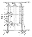
FIG. 1 is a top view of an embodiment of a heater assembly; -
FIGS. 2A and 2B are a side view and a top view, respectively, of an insulator support structure in accordance with the embodiment ofFIG. 1 ; -
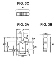
FIGS. 3A, 3B, and 3C are a side view, a top view, and an end view, respectively, of an insulator support structure in accordance with the embodiment ofFIG. 1 ; -
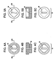
FIGS. 4A, 4B, and 4C are a front end view, a cross sectional view along line A-A ofFIG. 4A , and a rear end view, respectively, of a male ceramic spacer structure in accordance with the embodiment ofFIG. 1 ; -
FIGS. 5A, 5B, and 5C are a front end view, a cross sectional view along line A-A ofFIG. 5A , and a rear end view, respectively, of a female ceramic spacer structure in accordance with the embodiment ofFIG. 1 ; -
FIG. 6 is a side view of one embodiment of a welding clip; -
FIG. 7 is a side view of one embodiment of a clinching clip; -
FIG. 8 is a top view of one embodiment of a T-shaped bar; -
FIG. 9 is a side view of the clinching clip ofFIG. 7 attached to the T-shaped bar ofFIG. 8 ; -
FIG. 10 is a top view of the clinching clip ofFIG. 7 attached to the T-shaped bar ofFIG. 8 and the insulator support structure ofFIG. 2A ; and -
FIG. 11 is a top view of one embodiment of a terminal structure. -
FIG. 1 illustrates a top view of one embodiment of aheater assembly 10, including amounting structure 15, asecurement structure 20, aninsulator support structure 25, aterminal structure 30, a conductingstructure 35, and athermostat structure 40. Thethermostat structure 40 may include an in-line thermostat structure. - The
insulator support structure 25 includes afirst portion 26, asecond portion 27, and a third portion 28 (seeFIG. 2 ). The first portion26 of theinsulator support structure 25 may include a center portion. Thesecond portion 27 of theinsulator support structure 25 may include a first end portion, and a terminal receiving opening 29 formed therethrough. Thethird portion 28 of theinsulator support structure 25 may' include a second end portion, and a conductor receiving opening1 I formed therethrough. The terminal, receiving opening 29 and/or the conductor receiving opening 11 of theinsulator support structure 25 may extend to an outer edge portion of theinsulator support structure 25. The size of theinsulator support structure 25 may include the following measurements (seeFIGS. 2A and 2B ): LI =11.430 mm; L2=25,756 mm; L3=51.308 mm; L4=1.270 mm; L5= 15.875 mm; L6=35.712 mm; L7=22.098 mm; L8=15.875; L=10.033 mm; L10=3.175 mm:LI 1=1.778 mm; and L12=5.283 mm. - The
terminal structure 30 includes afirst portion 31, and a second portion 32 (seeFIG. 11 ). The conductingstructure 35 includes afirst portion 36, and a second portion 37 (seeFIG. 1 ). - The
securement structure 20 cooperates with thefirst portion 26 of theinsulator support structure 25 and themounting structure 15 to releasably and fixedly secure theinsulator support structure 25 to themounting structure 15. The securement structure 20 (seeFIGS. 6 and 7 ) may include afirst portion 21 to engage with thefirst portion 26 of theinsulator support structure 25, and asecond portion 22 to engage with themounting structure 15. Thefirst portion 21 and thesecond portion 22 of thesecurement structure 20 may include a tab (e.g., a projection). Thefirst portion 26 of theinsulator support structure 25 may include a tab receiving opening 12 (seeFIG. 2 ) to receive thetab 21. Thesecond portion 22 of thesecurement structure 20 may be welded and/or clinched to themounting structure 15. -
FIG. 6 illustrates one embodiment of a clip (e.g., a double welding clip), andFIG. 7 illustrates another embodiment of a clip (e.g., a double clinching clip), each of which may be used to secure a pair ofinsulator support structures 25 to themounting structure 15. Thesecurement structure 20, however, may include a double clip, illustrated inFIGS. 6 and 7 , and/or a half clip, illustrated inFIG. 1 . The half clip may be used to secure a singleinsulator support structure 25 to themounting structure 15. - The
mounting structure 15 may include an outer surface having a round-shaped cross section with respect to an axis of the mounting structure 15 (seeFIG. 1 ). As such, the second portion 22 (e.g., the tab 22) of thesecurement structure 20 may be welded to the outer surface of the mounting structure 15 (seeFIGS. 1 and6 ). Also, the mountingstructure 15 may include an outer surface having a T-shaped cross section with respect to an axis of the mounting structure 15 (seeFIG. 8 ). As such, the second portion 22 (e.g., the tab 22) of thesecurement structure 20 may be clinched and/or welded to the outer surface of the mountingstructure 15 having the T-shaped cross section (seeFIGS. 7-10 ). In addition, the mountingstructure 15 may include a frame rail, for example, containing the outer surface having the round-shaped (seeFIG. 1 ) and/or the T-shaped (seeFIGS. 8-10 ) cross section with respect to an axis of the frame rail. - The
tab 22 of thesecurement structure 20 may include a bendable clinching tab (seeFIG. 7 ) that may be formed for clinching to the mountingstructure 15 such as, for example, thetab receiving portion 16 of the mountingstructure 15. Thebendable clinching tab 22 of thesecurement structure 20, may include a T-shaped structure containing a ridge portion and a stem portion. The ridge portion of thesecurement structure 20 may include a set of end portions that form bendable flaps that are bendable around the mounting structure 15 (e.g., thetab receiving portion 16 of the mounting structure 15). - The
second portion 27 of the insulator support structure 25 (seeFIG. 2 ) cooperates with the terminal structure 30 (seeFIG. 1 ) to releasably and fixedly secure theterminal structure 30 to theinsulator support structure 25. Theterminal receiving opening 29 may cooperate with theterminal structure 30 to releasably and fixedly secure theterminal structure 30 to theinsulator support structure 25. - The
terminal structure 30 may include an outer surface having at least one of a first shaped cross section and a second shaped cross section with respect to an axis of theterminal structure 30. The first shaped cross section may include one of round, square, rectangular and elliptical, and the second shaped cross section may include another of the one of round, square, rectangular and elliptical. Thesecond portion 27 of theinsulator support structure 25 may receive the first shaped cross section and/or the second shaped cross section. - The
third portion 28 of theinsulator support structure 25 cooperates with thefirst portion 36 of the conductingstructure 35 to releasably and fixedly secure the conductingstructure 35 to theinsulator support structure 25. Theconductor receiving opening 11 may cooperate with thefirst portion 36 of the conductingstructure 35 to releasably and fixedly secure the conductingstructure 35 to theinsulator support structure 25. - The
first portion 31 of theterminal structure 30 is coupled to the second portion 37 of the conductingstructure 35, and thesecond portion 32 of theterminal structure 30 is coupled to thethermostat structure 40. Thefirst portion 31 of theterminal structure 30 may be coupled to the second portion 37 of the conductingstructure 35 by crimping around thefirst portion 31 of theterminal structure 30 to the second portion 37 of the conductingstructure 35. Thesecond portion 32 of theterminal structure 30 may include afastener receiving opening 33 formed therethrough (seeFIG. 11 ). Thethermostat structure 40 may include a corresponding threaded fastener receiving opening (not shown) formed therethrough. To couple theterminal structure 30 to thethermostat structure 40, then theterminal structure 30 may be placed against thethermostat structure 40 with the fastener receiving openings in alignment. A fastener 41 (e.g., threaded bolt) may be inserted through thefastener receiving opening 33 of theterminal structure 30 and threaded onto the threaded fastener receiving opening of thethermostat structure 40 and tightened to couple theterminal structure 30 to thethermostat structure 40. - The
insulator support structure 25 then supports thethermostat structure 40 and the conductingstructure 35 in position. - An embodiment of a method for assembling the above-mentioned
heater assembly 10 is provided. The method secures, through thesecurement structure 20, theinsulator support structure 25 to the mountingstructure 15. The method also secures theterminal structure 30 and the conductingstructure 35 to theinsulator support structure 25. The method further supports thethermostat structure 40 and the conductingstructure 35 in position using theinsulator support structure 25. -
FIG. 1 illustrates a top view of another embodiment of aheater assembly 10, including a mountingstructure 15, asecurement structure 20, aninsulator support structure 45, aterminal structure 50, and a conductingstructure 35. - As described above, the
securement structure 20 cooperates with theinsulator support structure 45 and the mountingstructure 15 to releasably and fixedly secure theinsulator support structure 45 to the mountingstructure 15. - The
insulator support structure 45 includes aterminal receiving opening 29 formed therethrough (seeFIG.3 ). Theterminal structure 50 includes an outer surface having a first shaped cross section and/or a second shaped cross section with respect to an axis of theterminal structure 50, and it is coupled to the conductingstructure 35. - The
terminal receiving opening 29 of theinsulator support structure 45 cooperates with theterminal structure 50 to releasably and fixedly secure theterminal structure 50 to theinsulator support structure 45. Theterminal receiving opening 29 may be constructed and arranged to receive the first shaped cross section and the second shaped cross section of theterminal structure 50. The first shaped cross section may include one of round, square, rectangular and elliptical, and the second shaped cross section may include another of the one of round, square, rectangular and elliptical. - The size of the
insulator support structure 45 may include the following measurements (seeFIGS. 3A and 3B ): L30=22.098 mm; L31=3.353 mm; L32=10.033 mm; L33=15.875 mm; L34=1.778 mm; L35=1.270 mm; L36=3.962 mm; L37=17.500 mm; L38=25.502 mm; and L39=5.2832 mm. - The
insulator support structure 45 may be coupled to a spacer structure 55 (e. g., a male ceramic spacer (seeFIG. 4 )and/or a female ceramic spacer (seeFIG. 5 )) to function as a support for a terminal structure delivering electrical power to a conducting structure. As such, thespacer structure 55 may include aterminal receiving opening 56 formed therethrough. To secure theterminal structure 50 to theinsulator support structure 45, then thespacer structure 55 is placed against theinsulator support structure 45 with theterminal receiving opening 56 of thespacer structure 55 and theterminal receiving opening 29 of theinsulator support structure 45 in alignment, and theterminal structure 50 is inserted through the terminal receiving openings. The terminal structure 50 (seeFIG. 1 ) may include aprojection 51 to engage with thespacer structure 50 to secure theterminal structure 50 to theinsulator support structure 45.FIG. 1 illustrates the heater assembly including a female ceramic spacer, illustrated inFIG. 5 . - An embodiment of a method for assembling the above-mentioned
heater assembly 10 is provided. The method secures, through thesecurement structure 20, theinsulator support structure 45 to the mountingstructure 15. Theterminal structure 50 is coupled to the conductingstructure 35. The method then secures theterminal structure 50 to theinsulator support structure 45. -
FIG. 1 illustrates a top view of a further embodiment of aheater assembly 10, including a mountingstructure 15, asecurement structure 20, aninsulator support structure 25, 45 (e.g., theinsulator support structure 25 and/or theinsulator support structure 45, both of which may include aterminal receiving opening 29 formed therethrough), a conductingstructure 35, aterminal structure 50, and athermostat structure 40. The conductingstructure 35 includes afirst portion 38 and a second portion 37. Thethermostat structure 40 may include an in-line thermostat structure. - As described above, the securement structure 20 (e.g., a clipping structure) cooperates with the
insulator support structure structure 15 to releasably and fixedly secure theinsulator support structure structure 15. - The
terminal structure 50 is coupled to thefirst portion 38 of the conductingstructure 35 to deliver power to the conductingstructure 35. Thethermostat structure 40 is directly or indirectly coupled to the second portion 37 of the conducting structure 35 (see, for example, above). - The
insulator support structure terminal structure 50 and thethermostat structure 40 to support (e.g., fixedly support) theterminal structure 50 and/or thethermostat structure 40 in position. Theterminal structure 50 and/or thethermostat structure 40 may include an outer surface having a first shaped cross section and/or a second shaped cross section with respect to an axis of theterminal structure 50 and/or thethermostat structure 40. Theinsulator support structure - An embodiment of a method for assembling the above-mentioned
heater assembly 10 is provided. The method secures, though thesecurement structure 20, theinsulator support structure structure 15. Theterminal structure 50 and thethermostat structure 40 are coupled to the conductingstructure 35. The method then supports theterminal structure 50 and/or thethermostat structure 40 in position using theinsulator support structure - Thus, the
heater assembly 10 may include an in-line thermostat, and insulator support structures, where the insulator support structures may be of one type and/or may be retained by clips welded to frame bars and/or clinched to T-shaped frame bars of theheater assembly 10. Also, theheater assembly 10 allows for the clips to be of one type, like the insulator support structures. As such, theheater assembly 10 allows, for example, for the use of more standardized parts and manufacturing procedures, and thereby theheater assembly 10 may be manufactured at a reduced cost, compared to presently known heater assemblies. -
FIG. 1 then illustrates one embodiment of aheater assembly 10, for example; using half clips 20 (see, for example,FIG. 6 , which illustrates a double welding clip) welded to frame bars 15. Other embodiments are also possible, for example, using half clips 20 (see, for example,FIG. 7 , which illustrates a double clinching clip) clinched to T-shaped cross section frame bars 15 (seeFIGS. 8-10 ), with flat bushings and/or point suspension insulators supporting the heating element coil 35 (e.g., electric heating coil). -
FIGS. 2A and 2B illustrate one embodiment of a double endedflat insulator 25 having a first end with a first slot, a second end with a second slot, and a center portion with two slots (e.g., rectangular slots at opposite edges of the center portion). On the other hand,FIGS. 3A, 3B, and 3C illustrate one embodiment of a single endedflat insulator 45. - The two opposed, center slots allow the
ceramics insulators FIGS. 6 and 7 . Theclip 20 ofFig. 6 allows an insulator to be supported, for example, to a frame bar by welding. Theclip 20 ofFIG. 7 , on the other hand, allows an insulator to be supported, for example, to a frame bar by clinching. Half clip versions ofFIGS. 6 and 7 may also be used. - The slots (e.g., closed and/or open slots) in the ends of the flat insulators of
FIGS. 2 and3 may be used, for example, for various functions. For instance, a slot may accept different types of terminal configurations such as a round cross section threaded terminal, a round cross section threaded terminal with a square shoulder and/or a flat blade terminal(e.g., a thermostat mounting blade terminal (seeFIG. 11 )). - Also, the slot may allow the insulator to function as a support for a thermostat (e. g. an in-line thermostat) or as a ceramic to support a terminal delivering electrical power to a heating element. The flat insulators may be coupled to a spacer ceramic (see
FIGS. 4 and 5 ) to function as a terminal support for delivering electrical power. - The size, shape, material and/or arrangement of the mounting
structure 15, thesecurement structure 20, the insulator support structure25, 45, theterminal structure structure 35, and/or thethermostat structure 40 may be varied according to the preference of a user of theheater assembly 10. Also, an open coil electric heater may include an in-line thermostat that may be directly or indirectly mounted to a frame member by weldingand/or clinching to a T-shaped cross section of the frame member. A flat ceramic may include a first opening on one end of the ceramic that is multifunctional (see, for example, above). The flat ceramic may also include two slots on opposite sides of a center portion of the ceramic for accepting clips for supporting the ceramic to the frame. Moreover, the ceramic may include a second opening on another end of the ceramic for supporting a helical wound resistance wire.
Claims (40)
- A heater assembly (10) comprising:a mounting structure (15);a conducting structure (35), including a first portion (36, 38) and a second portion (37);a terminal structure (30, 50); anda thermostat structure (40),characterised in that the heater assembly (10) further comprises:a securement structure (20); andan insulator support structure (25, 45);wherein the securement structure (20) is constructed and arranged to cooperate with the insulator support structure (25, 45) and the mounting structure (15) to releasably and fixedly secure the insulator support structure (25, 45) to the mounting structure (15),
wherein the terminal structure (30, 50) is constructed and arranged to be coupled to the first portion (38) of the conducting structure (35), and to deliver power to the conducting structure (35),
wherein the thermostat structure (40) is constructed and arranged to be coupled to the second portion (37) of the conducting structure (35), and
wherein the insulator support structure (25, 45) is constructed and arranged to cooperate with the terminal structure (30, 50) and the thermostat structure (40) to fixedly support one of the terminal structure (30, 50) and the thermostat structure (40) in position. - The heater assembly (10) of claim 9, wherein
the insulator support structure (25, 45) includes a terminal receiving opening (29) formed therethrough;
the terminal structure (30, 50) includes an outer surface having at least one of a first shaped cross section and a second shaped cross section with respect to an axis of the terminal structure; and
wherein the terminal receiving opening (29) of the insulator support structure (25, 45) is constructed and arranged to cooperate with the terminal structure (30, 50) to releasably and fixedly secure the terminal structure (30, 50) to the insulator support structure (25, 45), and to receive the first shaped cross section and the second shaped cross section. - The heater assembly (10) of claim 1, wherein
the insulator support structure (25, 45) includes a first portion (26), a second portion (27), and a third portion (28);
the terminal structure (30, 50) includes a first portion (31), and a second portion (32);
wherein the securement structure (20) is constructed and arranged to cooperate with the first portion (26) of the insulator support structure (25, 45);
wherein the second portion (27) of the insulator support structure (25, 45) is constructed and arranged to cooperate with the terminal structure (30, 50) to releasably and fixedly secure the terminal structure (30, 50) to the insulator support structure (25, 45),
wherein the third portion (28) of the insulator support structure (25, 45) is constructed and arranged to cooperate with the first portion (36) of the conducting structure (35) to releasably and fixedly secure the conducting structure (35) to the insulator support structure (25, 45),
wherein the first portion (31) of the terminal structure (30, 50) is constructed and arranged to be coupled to the second portion (37) of the conducting structure (35), and the second portion (32) of the terminal structure (30, 50) is constructed and arranged to be coupled to the thermostat structure (40), and
wherein the insulator support structure (25, 45) is constructed and arranged to support the thermostat structure (40) and the conducting structure (35) in position. - The heater assembly of claim 3,
wherein the first portion (26) of the insulator support structure (25, 45) includes a center portion of the insulator support structure (25, 45),
wherein the second portion (27) of the insulator support structure (25, 45) includes a first end portion of the insulator support structure (25, 45), and
wherein the third portion (28) of the insulator support structure (25, 45) includes a second end portion of the insulator support structure (25, 45). - The heater assembly of claim 3 or claim 4,
wherein the second portion (27) of the insulator support structure (25, 45) includes a terminal receiving opening (29) formed therethrough, and
wherein the terminal receiving opening (29) is constructed and arranged to cooperate with the terminal structure (30, 50) to releasably and fixedly secure the terminal structure (30, 50) to the insulator support structure (25, 45). - The heater assembly of claim 5, wherein the terminal receiving opening (29) of the insulator support structure (25, 45) is constructed and arranged to extend to an outer edge portion of the insulator support structure (25, 45).
- The heater assembly (10) according to any one of claims 3 to 6,
wherein the third portion (28) of the insulator support structure (25, 45) includes a conductor receiving opening (11) formed therethrough, and
wherein the conductor receiving opening (11) is constructed and arranged to cooperate with the first portion (31) of the conducting structure (35) to releasably and fixedly secure the conducting structure (35) to the insulator support structure (25, 45). - The heater assembly (10) of claim 7, wherein the conductor receiving opening (11) of the insulator support structure (25, 45) is constructed and arranged to extend to an outer edge portion of the insulator support structure (25, 45).
- The heater assembly (10) according to any one of claims 1, 2 or 3,
wherein the securement structure (20) includes a first portion (21) to engage with the first portion (26) of the insulator support structure (25, 45), and a second portion (22) to engage with the mounting structure (15). - The heater assembly (10) of claim 9,
wherein the first portion (21) of the securement structure (20) includes a tab, and
wherein the first portion (26) of the insulator support structure (25, 45) includes a tab receiving opening (12), constructed and arranged to receive the tab (21). - The heater assembly (10) of claim 9 or claim 10,
wherein the second portion (22) of the securement structure (20) includes a tab, and
wherein the mounting structure (15) includes a tab receiving portion (16), constructed and arranged to receive the tab (22). - The heater assembly (10) according to any one of claims 9 to 11,
wherein the second portion (22) of the securement structure (20) is welded to the mounting structure (15). - The heater assembly (10) according to any one of claims 9 to 12,
wherein the second portion (22) of the securement structure (20) includes a bendable clinching tab, constructed and arranged for clinching to the mounting structure (15). - The heater assembly (10) of claim 13,
wherein the mounting structure (15) includes an outer surface having a T-shaped cross section with respect to an axis of the mounting structure (15), and
wherein the bendable clinching tab of the securement structure (20) is clinched to the outer surface of the mounting structure (15) having the T-shaped cross section. - The heater assembly (10) of claim 13 or claim 14,
wherein the bendable clinching tab of the securement structure (20) includes a T-shaped structure containing a ridge portion and a stem portion. - The heater assembly (10) of claim 15,
wherein the ridge portion of the securement structure includes a set of end portions, constructed and arranged to form bendable flaps that are bendable around the mounting structure. - The heater assembly (10) according to any one of claims 9 to 16,
wherein the second portion (22) of the securement structure (20) is constructed and arranged to be welded to and to be clinched to the mounting structure (15). - The heater assembly (10) according to any one of claims 9 to 17,
wherein the mounting structure (15) includes a frame rail. - The heater assembly (10) according to any one of claims 1 to 18,
wherein the thermostat structure (40) includes an in-line thermostat structure. - The heater assembly (10) of claim 2 or claim 3,
wherein the terminal structure (30, 50) includes an outer surface having at least one of a first shaped cross section and a second shaped cross section with respect to an axis of the terminal structure, and
wherein the second portion (27) of the insulator support structure (25, 45) is constructed and arranged to receive the first shaped cross section and the second shaped cross section. - The heater assembly (10) of claim 1,
wherein at least one of the terminal structure (30, 50) and the thermostat structure (40) includes an outer surface having at least one of a first shaped cross section and a second shaped cross section with respect to an axis of the at least one of the terminal structure (30, 50) and the thermostat structure (40), and
wherein the insulator support structure (25, 45) is constructed and arranged to cooperate with the first shaped cross section and the second shaped cross section. - The heater assembly (10) of any one of claims 2, 20, and 21,
wherein the first shaped cross section includes one of round, square, rectangular and elliptical, and
wherein the second shaped cross section includes another of the one of round, square, rectangular and elliptical. - The heater assembly (90) according to any one of claims 1 to 22,
wherein the securement structure (20) includes a clipping structure. - A method for assembling a heater (10) comprising:coupling a terminal structure (30, 50) and a thermostat structure (40) to a conducting structure (35);wherein the conducting structure (35) includes a first portion (36) and a second portion (37),
characterised in that the method further comprises:securing, though a securement structure (20), an insulator support structure (25, 45) to a mounting structure (15);supporting one of the terminal structure (30, 50) and the thermostat structure (40) in position using the insulator support structure (25, 45),wherein the securement structure (20) is constructed and arranged to cooperate with the insulator support structure (25, 45) and the mounting structure (15) to releasably and fixedly secure the insulator support structure (25, 45) to the mounting structure (15),
wherein the terminal structure (30, 50) is constructed and arranged to be coupled to the first portion (36) of the conducting structure (35) and to deliver power to the conducting structure (35),
wherein the thermostat structure (40) is constructed and arranged to be coupled to the second portion (37) of the conducting structure (35), and
wherein the insulator support structure (25, 45) is constructed and arranged to cooperate with the terminal structure (30, 50) and the thermostat structure (40) to fixedly support one of the terminal structure (30, 50) and the thermostat structure (40) in position. - The method of claim 24,
wherein the insulator support structure (25, 45) includes a terminal receiving opening (29) formed therethrough,
wherein the terminal structure (30, 50) includes an outer surface having at least one of a first shaped cross section and a second shaped cross section with respect to an axis of the terminal structure (30, 50).
wherein the terminal receiving opening (29) of the insulator support structure (25, 45) is constructed and arranged to cooperate with the terminal structure (30, 50) to releasably and fixedly secure the terminal structure (30, 50) to the insulator support structure (25, 45), and to receive the first shaped cross section and the second shaped cross section. - The method of claim 24, wherein
securing a terminal structure (30, 50) and a conducting structure (35) to the insulator support structure (25, 45); and
supporting a thermostat structure (40) and the conducting structure (35) in position using the insulator support structure (25, 45),
wherein the insulator support structure (25, 45) includes a first portion (26), a second portion (27), and a third portion (28),
wherein the terminal structure (30) includes a first portion (31), and a second portion (32),
wherein the conducting structure (35) includes a first portion (36), and a second portion (37),
wherein the securement structure (20) is constructed and arranged to cooperate with the first portion (26) of the insulator support structure (25, 45) and the mounting structure (15) to releasably and fixedly secure the insulator support structure (25, 45) to the mounting structure (15),
wherein the second portion (27) of the insulator support structure (25, 45) is constructed and arranged to cooperate with the terminal structure (30, 50) to releasably and fixedly secure the terminal structure (30, 50) to the insulator support structure (25, 45),
wherein the third portion (38) of the insulator support structure (25, 45) is constructed and arranged to cooperate with the first portion (36) of the conducting structure (35) to releasably and fixedly secure the conducting structure (35) to the insulator support structure (25, 45), and
wherein the first portion (31) of the terminal structure (30, 50) is constructed and arranged to be coupled to the second portion (37) of the conducting structure (35), and the second portion (32) of the terminal structure (30, 50) is constructed and arranged to be coupled to the thermostat structure (40). - The method of claim 26,
wherein the first portion (26) of the insulator support structure (25, 45) includes a center portion of the insulator support structure (25, 45),
wherein the second portion (27) of the insulator support structure (25, 45) includes a first end portion of the insulator support structure (25, 45), and
wherein the third portion (28) of the insulator support structure (25, 45) includes a second end portion of the insulator support structure (25, 45). - The method of claim 26 or claim 27,
wherein the second portion (27) of the insulator support structure (25, 45) includes a terminal receiving opening (29) formed therethrough, and
wherein the terminal receiving opening (29) is constructed and arranged to cooperate with the terminal structure (30, 50) to releasably and fixedly secure the terminal structure (30, 50) to the insulator support structure (25, 45). - The method according to any one of claim 26 to 28,
wherein the third portion (28) of the insulator support structure (25, 45) includes a conductor receiving opening (11) formed therethrough, and
wherein the conductor receiving opening (11) is constructed and arranged to cooperate with the first portion (36) of the conducting structure (35) to releasably and fixedly secure the conducting structure (35) to the insulator support structure (25, 45). - The method of any one of claims 24, 25, and 26, wherein the securement structure (20) includes a first portion (21) to engage with the first portion (26) of the insulator support structure (25, 45), and a second portion (22) to engage with the mounting structure (15).
- The method of claim 30,
wherein the first portion (21) of the securement structure (20) includes a tab, and
wherein the first portion (26) of the insulator support structure (25, 45) includes a tab receiving opening (12), constructed and arranged to receive the tab (21). - The method of claim 30,
wherein the second portion (22) of the securement structure (20) includes a tab, and
wherein the mounting structure (15) includes a tab receiving portion (16), constructed and arranged to receive the tab (22). - The method of claim 30, wherein the second portion (22) of the securement structure is welded to the mounting structure (15).
- The method of claim 30, wherein the second portion (22) of the securement structure (20) includes a bendable clinching tab, constructed and arranged for clinching to the mounting structure (15).
- The method of claim 34,
wherein the mounting structure (15) includes an outer surface having a T-shaped cross section with respect to an axis of the mounting structure (15), and
wherein the bendable clinching tab of the securement structure (20) is clinched to the outer surface of the mounting structure (15) having the T-shaped cross section. - The method of claim 30, wherein the second portion (22) of the securement structure (20) is constructed and arranged to be welded to and to be clinched to the mounting structure (15).
- The method of claim 26,
wherein the terminal structure (30, 50) includes an outer surface having at least one of a first shaped cross section and a second shaped cross section with respect to an axis of the terminal structure (30, 50), and
wherein the second portion (27) of the insulator support structure (25, 45) is constructed and arranged to receive the first shaped cross section and the second shaped cross section. - The method of claim 37,
wherein the first shaped cross section includes one of round, square, rectangular and elliptical, and
wherein the second shaped cross section includes another of the one of round, square, rectangular and elliptical. - The method according to any one of claims 31, 32, and 38,
wherein the first shaped cross section includes one of round, square, rectangular and elliptical, and
wherein the second shaped cross section includes another of the one of round, square, rectangular and elliptical. - The method of claim 24, wherein the securement structure (20) includes a clipping structure.
Applications Claiming Priority (3)
| Application Number | Priority Date | Filing Date | Title |
|---|---|---|---|
| US09/997,252 US6624398B2 (en) | 2001-11-30 | 2001-11-30 | Insulator support structure for a heater assembly |
| US997252 | 2001-11-30 | ||
| PCT/US2002/037467 WO2003049501A2 (en) | 2001-11-30 | 2002-11-22 | Improved insulator support structure for a heater assembly |
Publications (3)
| Publication Number | Publication Date |
|---|---|
| EP1449406A2 EP1449406A2 (en) | 2004-08-25 |
| EP1449406A4 EP1449406A4 (en) | 2007-05-09 |
| EP1449406B1 true EP1449406B1 (en) | 2009-04-01 |
Family
ID=25543795
Family Applications (1)
| Application Number | Title | Priority Date | Filing Date |
|---|---|---|---|
| EP02795663A Expired - Lifetime EP1449406B1 (en) | 2001-11-30 | 2002-11-22 | Improved insulator support structure for a heater assembly |
Country Status (11)
| Country | Link |
|---|---|
| US (1) | US6624398B2 (en) |
| EP (1) | EP1449406B1 (en) |
| JP (1) | JP4059850B2 (en) |
| KR (1) | KR100771717B1 (en) |
| CN (1) | CN100338971C (en) |
| AT (1) | ATE427641T1 (en) |
| AU (1) | AU2002360410A1 (en) |
| CA (1) | CA2436849C (en) |
| DE (1) | DE60231827D1 (en) |
| MX (1) | MXPA03006881A (en) |
| WO (1) | WO2003049501A2 (en) |
Families Citing this family (17)
| Publication number | Priority date | Publication date | Assignee | Title |
|---|---|---|---|---|
| US6600141B1 (en) * | 2002-04-12 | 2003-07-29 | Tutco, Inc. | Thermostat assembly for a heater |
| US7053336B1 (en) * | 2005-01-28 | 2006-05-30 | Hsien-Kuan Cheng | Heating element autobalance device |
| US7442904B2 (en) * | 2005-02-25 | 2008-10-28 | Tutco, Inc. | Metal sheathed heater and thermostat assembly and method of use |
| US20080230619A1 (en) * | 2007-03-21 | 2008-09-25 | Robert Kirby | Heating or heating and air conditioning unit with noise abatement feature and method of use |
| DE102009038341A1 (en) * | 2009-08-21 | 2011-04-21 | Von Ardenne Anlagentechnik Gmbh | Heating device for a substrate treatment device and substrate treatment device |
| US8538249B2 (en) * | 2009-10-20 | 2013-09-17 | General Electric Company | Broiler for cooking appliances |
| US10880954B2 (en) * | 2010-11-05 | 2020-12-29 | Tutco, Llc | Foldable electric resistance heater and method of use |
| US20140044424A1 (en) * | 2012-08-10 | 2014-02-13 | Stelpro Design Inc. | Heating vent conduit |
| US9743987B2 (en) | 2013-03-14 | 2017-08-29 | Board Of Regents Of The University Of Nebraska | Methods, systems, and devices relating to robotic surgical devices, end effectors, and controllers |
| US10251217B2 (en) * | 2013-06-14 | 2019-04-02 | Sandvik Kk | Molybdenum disilicide-based ceramic heating element holding structure |
| KR101818128B1 (en) * | 2015-12-11 | 2018-01-22 | (주)마이텍 | Real-time temperature controllable electric heater equipped with self-diagnosis function for marine vessel and offshore plant |
| KR101792361B1 (en) * | 2015-12-11 | 2017-11-08 | 동명대학교산학협력단 | Compact energy saving electric Heater for marine vessel and offshore plant |
| WO2018098319A1 (en) | 2016-11-22 | 2018-05-31 | Board Of Regents Of The University Of Nebraska | Improved gross positioning device and related systems and methods |
| WO2018112199A1 (en) | 2016-12-14 | 2018-06-21 | Virtual Incision Corporation | Releasable attachment device for coupling to medical devices and related systems and methods |
| CA3080880C (en) | 2019-06-05 | 2025-05-13 | Tutco, Llc | Monobloc heating device frame, heating assembly using the heating device frame, and method of use |
| CN110267374A (en) * | 2019-06-17 | 2019-09-20 | 东莞市金烨电热材料有限公司 | Special electric heating plate applied to enamel kiln |
| JP2023532977A (en) | 2020-07-06 | 2023-08-01 | バーチャル インシジョン コーポレイション | Surgical robotic positioning system and related apparatus and methods |
Family Cites Families (24)
| Publication number | Priority date | Publication date | Assignee | Title |
|---|---|---|---|---|
| US3631525A (en) | 1969-11-24 | 1971-12-28 | Jerome F Brasch | Electric heater for use in a duct work system |
| US6509554B2 (en) * | 2000-08-23 | 2003-01-21 | Tutco, Inc. | Support clips and insulators for use in electric heaters and electric heaters containing same |
| US3641312A (en) | 1970-06-23 | 1972-02-08 | Heatcraft | Open coil heating element assembly |
| US3770939A (en) | 1972-09-19 | 1973-11-06 | Emerson Electric Co | Electric heating assemblies |
| US3811031A (en) | 1973-01-29 | 1974-05-14 | Tpi Corp | Duct electrical heater unit |
| US3890487A (en) | 1974-03-04 | 1975-06-17 | Emerson Electric Co | Open coil heater having spaced end coils |
| US4289955A (en) | 1979-11-05 | 1981-09-15 | Emerson Electric Co. | Electric heating assemblies with a mounted thermostatic switch |
| US4492851A (en) * | 1980-12-29 | 1985-01-08 | Brazeway, Inc. | Swap action arrangement mounting an electric defroster heater to a finned refrigeration unit |
| US4472624A (en) | 1982-06-10 | 1984-09-18 | Emerson Electric Co. | Electric resistance heater |
| US4531017A (en) * | 1983-11-25 | 1985-07-23 | Tutco, Inc. | Insulator for an electric heater |
| US4481411A (en) * | 1983-12-21 | 1984-11-06 | Intertherm Inc. | Electrical heater rack assembly with stand-off insulators |
| US4617547A (en) * | 1984-04-20 | 1986-10-14 | Tutco, Inc. | Heater assembly |
| US4628189A (en) * | 1985-02-11 | 1986-12-09 | Emerson Electric Co. | Electric resistance heater |
| US5641420A (en) | 1995-09-06 | 1997-06-24 | Lakewood Engineering & Mfg. Co. | Electric heater having coil with loop that passes through aperture in support |
| US6078730A (en) * | 1995-11-13 | 2000-06-20 | Fisher & Paykel Limited | Heat respiratory conduit |
| US5959254A (en) * | 1996-10-07 | 1999-09-28 | Martin, Sr.; Lendell | Tapered support insulator for heating elements having curved surface grooves for retention of the heating elements |
| SE508779C2 (en) * | 1997-01-29 | 1998-11-02 | Kanthal Ab | Infrared radiating panel |
| US5954983A (en) * | 1997-09-29 | 1999-09-21 | Nova Industries | Heating coil standoff and support structure |
| US5925273A (en) * | 1997-10-20 | 1999-07-20 | Tutco, Inc. | Electric multi-stage heater assembly |
| US6097003A (en) | 1998-01-09 | 2000-08-01 | Emerson Electric Company | Support bar attachment for an electric heater element |
| US6433318B2 (en) * | 2000-08-11 | 2002-08-13 | Michael Danko | Electric heater assembly with in-line thermostat |
| US6596974B2 (en) * | 2000-09-21 | 2003-07-22 | Tutco, Inc. | Support apparatus for resistive coils and insulators in electric heaters |
| US6359262B1 (en) * | 2000-10-26 | 2002-03-19 | Emerson Electric Co. | Support bracket for heater element in bake oven |
| KR100859629B1 (en) * | 2001-04-27 | 2008-09-23 | 투트코 인코포레이티드 | Method and apparatus for mounting heater thermostats and temperature sensitive fuses |
-
2001
- 2001-11-30 US US09/997,252 patent/US6624398B2/en not_active Expired - Lifetime
-
2002
- 2002-11-22 AT AT02795663T patent/ATE427641T1/en not_active IP Right Cessation
- 2002-11-22 WO PCT/US2002/037467 patent/WO2003049501A2/en not_active Ceased
- 2002-11-22 CA CA2436849A patent/CA2436849C/en not_active Expired - Fee Related
- 2002-11-22 JP JP2003550557A patent/JP4059850B2/en not_active Expired - Fee Related
- 2002-11-22 DE DE60231827T patent/DE60231827D1/en not_active Expired - Fee Related
- 2002-11-22 AU AU2002360410A patent/AU2002360410A1/en not_active Abandoned
- 2002-11-22 EP EP02795663A patent/EP1449406B1/en not_active Expired - Lifetime
- 2002-11-22 KR KR1020037010052A patent/KR100771717B1/en not_active Expired - Fee Related
- 2002-11-22 MX MXPA03006881A patent/MXPA03006881A/en active IP Right Grant
- 2002-11-22 CN CNB028043545A patent/CN100338971C/en not_active Expired - Lifetime
Also Published As
| Publication number | Publication date |
|---|---|
| JP4059850B2 (en) | 2008-03-12 |
| MXPA03006881A (en) | 2003-11-13 |
| CN1493170A (en) | 2004-04-28 |
| DE60231827D1 (en) | 2009-05-14 |
| CN100338971C (en) | 2007-09-19 |
| WO2003049501A2 (en) | 2003-06-12 |
| KR100771717B1 (en) | 2007-10-30 |
| KR20040068457A (en) | 2004-07-31 |
| WO2003049501A3 (en) | 2003-08-21 |
| AU2002360410A1 (en) | 2003-06-17 |
| CA2436849A1 (en) | 2003-06-12 |
| EP1449406A2 (en) | 2004-08-25 |
| US20030102301A1 (en) | 2003-06-05 |
| EP1449406A4 (en) | 2007-05-09 |
| JP2005512285A (en) | 2005-04-28 |
| ATE427641T1 (en) | 2009-04-15 |
| US6624398B2 (en) | 2003-09-23 |
| CA2436849C (en) | 2010-06-08 |
Similar Documents
| Publication | Publication Date | Title |
|---|---|---|
| CA2436849C (en) | Improved insulator support structure for a heater assembly | |
| US4250399A (en) | Electric heating elements | |
| US4458141A (en) | Electric heater and coil support insulator therefor | |
| KR100771750B1 (en) | Support clip and insulator for electric heater, and electric heater comprising the same | |
| EP0145192A2 (en) | Fusible electrical connector | |
| US6723968B2 (en) | Conductive U-shaped jumper strap and method of use | |
| US20100059504A1 (en) | Open coil resistance heater with right and left hand installation capability | |
| EP1606976B1 (en) | Mica board electrical resistance wire heater , subassemblies components, and methods of assembly | |
| US6770855B2 (en) | Methods of assembling open coil electrical resistance heaters involving butt welding of rails and using welded insulator support clips with bendable tabs | |
| US6624546B2 (en) | Radio-frequency interference suppressing choke with elongated portions for brush-type motors | |
| US6593553B2 (en) | Heating coil assembly and methods for assembling the same | |
| US6600141B1 (en) | Thermostat assembly for a heater | |
| EP0971461A2 (en) | Electrical busbar with female terminals | |
| JPS58103739A (en) | electromagnetic relay | |
| CA2361304A1 (en) | Electric heater assembly with in-line thermostat | |
| US8410406B1 (en) | Helical wire heating coil assemblies and methods for assembling helical wire heating coil assemblies | |
| JPH1077U (en) | Fuse holder for surface mounting | |
| JPH0110863Y2 (en) | ||
| JPH10233261A (en) | connector |
Legal Events
| Date | Code | Title | Description |
|---|---|---|---|
| PUAI | Public reference made under article 153(3) epc to a published international application that has entered the european phase |
Free format text: ORIGINAL CODE: 0009012 |
|
| 17P | Request for examination filed |
Effective date: 20030909 |
|
| AK | Designated contracting states |
Kind code of ref document: A2 Designated state(s): AT BE BG CH CY CZ DE DK EE ES FI FR GB GR IE IT LI LU MC NL PT SE SK TR |
|
| AX | Request for extension of the european patent |
Extension state: AL LT LV MK RO SI |
|
| A4 | Supplementary search report drawn up and despatched |
Effective date: 20070412 |
|
| RIC1 | Information provided on ipc code assigned before grant |
Ipc: H05B 3/06 20060101AFI20030617BHEP Ipc: H05B 3/46 20060101ALI20070404BHEP Ipc: H05B 3/16 20060101ALI20070404BHEP |
|
| 17Q | First examination report despatched |
Effective date: 20071116 |
|
| GRAP | Despatch of communication of intention to grant a patent |
Free format text: ORIGINAL CODE: EPIDOSNIGR1 |
|
| GRAS | Grant fee paid |
Free format text: ORIGINAL CODE: EPIDOSNIGR3 |
|
| GRAA | (expected) grant |
Free format text: ORIGINAL CODE: 0009210 |
|
| AK | Designated contracting states |
Kind code of ref document: B1 Designated state(s): AT BE BG CH CY CZ DE DK EE ES FI FR GB GR IE IT LI LU MC NL PT SE SK TR |
|
| REG | Reference to a national code |
Ref country code: GB Ref legal event code: FG4D |
|
| REG | Reference to a national code |
Ref country code: CH Ref legal event code: EP |
|
| REG | Reference to a national code |
Ref country code: IE Ref legal event code: FG4D |
|
| REF | Corresponds to: |
Ref document number: 60231827 Country of ref document: DE Date of ref document: 20090514 Kind code of ref document: P |
|
| NLV1 | Nl: lapsed or annulled due to failure to fulfill the requirements of art. 29p and 29m of the patents act | ||
| PG25 | Lapsed in a contracting state [announced via postgrant information from national office to epo] |
Ref country code: AT Free format text: LAPSE BECAUSE OF FAILURE TO SUBMIT A TRANSLATION OF THE DESCRIPTION OR TO PAY THE FEE WITHIN THE PRESCRIBED TIME-LIMIT Effective date: 20090401 Ref country code: FI Free format text: LAPSE BECAUSE OF FAILURE TO SUBMIT A TRANSLATION OF THE DESCRIPTION OR TO PAY THE FEE WITHIN THE PRESCRIBED TIME-LIMIT Effective date: 20090401 Ref country code: PT Free format text: LAPSE BECAUSE OF FAILURE TO SUBMIT A TRANSLATION OF THE DESCRIPTION OR TO PAY THE FEE WITHIN THE PRESCRIBED TIME-LIMIT Effective date: 20090902 Ref country code: ES Free format text: LAPSE BECAUSE OF FAILURE TO SUBMIT A TRANSLATION OF THE DESCRIPTION OR TO PAY THE FEE WITHIN THE PRESCRIBED TIME-LIMIT Effective date: 20090712 Ref country code: EE Free format text: LAPSE BECAUSE OF FAILURE TO SUBMIT A TRANSLATION OF THE DESCRIPTION OR TO PAY THE FEE WITHIN THE PRESCRIBED TIME-LIMIT Effective date: 20090401 |
|
| PG25 | Lapsed in a contracting state [announced via postgrant information from national office to epo] |
Ref country code: NL Free format text: LAPSE BECAUSE OF FAILURE TO SUBMIT A TRANSLATION OF THE DESCRIPTION OR TO PAY THE FEE WITHIN THE PRESCRIBED TIME-LIMIT Effective date: 20090401 Ref country code: SE Free format text: LAPSE BECAUSE OF FAILURE TO SUBMIT A TRANSLATION OF THE DESCRIPTION OR TO PAY THE FEE WITHIN THE PRESCRIBED TIME-LIMIT Effective date: 20090701 |
|
| PG25 | Lapsed in a contracting state [announced via postgrant information from national office to epo] |
Ref country code: DK Free format text: LAPSE BECAUSE OF FAILURE TO SUBMIT A TRANSLATION OF THE DESCRIPTION OR TO PAY THE FEE WITHIN THE PRESCRIBED TIME-LIMIT Effective date: 20090401 Ref country code: CZ Free format text: LAPSE BECAUSE OF FAILURE TO SUBMIT A TRANSLATION OF THE DESCRIPTION OR TO PAY THE FEE WITHIN THE PRESCRIBED TIME-LIMIT Effective date: 20090401 |
|
| PLBE | No opposition filed within time limit |
Free format text: ORIGINAL CODE: 0009261 |
|
| STAA | Information on the status of an ep patent application or granted ep patent |
Free format text: STATUS: NO OPPOSITION FILED WITHIN TIME LIMIT |
|
| PG25 | Lapsed in a contracting state [announced via postgrant information from national office to epo] |
Ref country code: SK Free format text: LAPSE BECAUSE OF FAILURE TO SUBMIT A TRANSLATION OF THE DESCRIPTION OR TO PAY THE FEE WITHIN THE PRESCRIBED TIME-LIMIT Effective date: 20090401 Ref country code: BE Free format text: LAPSE BECAUSE OF FAILURE TO SUBMIT A TRANSLATION OF THE DESCRIPTION OR TO PAY THE FEE WITHIN THE PRESCRIBED TIME-LIMIT Effective date: 20090401 |
|
| 26N | No opposition filed |
Effective date: 20100105 |
|
| PG25 | Lapsed in a contracting state [announced via postgrant information from national office to epo] |
Ref country code: BG Free format text: LAPSE BECAUSE OF FAILURE TO SUBMIT A TRANSLATION OF THE DESCRIPTION OR TO PAY THE FEE WITHIN THE PRESCRIBED TIME-LIMIT Effective date: 20090701 |
|
| PG25 | Lapsed in a contracting state [announced via postgrant information from national office to epo] |
Ref country code: MC Free format text: LAPSE BECAUSE OF NON-PAYMENT OF DUE FEES Effective date: 20091130 |
|
| REG | Reference to a national code |
Ref country code: CH Ref legal event code: PL |
|
| GBPC | Gb: european patent ceased through non-payment of renewal fee |
Effective date: 20091122 |
|
| REG | Reference to a national code |
Ref country code: IE Ref legal event code: MM4A |
|
| REG | Reference to a national code |
Ref country code: FR Ref legal event code: ST Effective date: 20100730 |
|
| PG25 | Lapsed in a contracting state [announced via postgrant information from national office to epo] |
Ref country code: LI Free format text: LAPSE BECAUSE OF NON-PAYMENT OF DUE FEES Effective date: 20091130 Ref country code: CH Free format text: LAPSE BECAUSE OF NON-PAYMENT OF DUE FEES Effective date: 20091130 Ref country code: FR Free format text: LAPSE BECAUSE OF NON-PAYMENT OF DUE FEES Effective date: 20091130 Ref country code: GR Free format text: LAPSE BECAUSE OF FAILURE TO SUBMIT A TRANSLATION OF THE DESCRIPTION OR TO PAY THE FEE WITHIN THE PRESCRIBED TIME-LIMIT Effective date: 20090702 Ref country code: IE Free format text: LAPSE BECAUSE OF NON-PAYMENT OF DUE FEES Effective date: 20091122 |
|
| PG25 | Lapsed in a contracting state [announced via postgrant information from national office to epo] |
Ref country code: DE Free format text: LAPSE BECAUSE OF NON-PAYMENT OF DUE FEES Effective date: 20100601 |
|
| PG25 | Lapsed in a contracting state [announced via postgrant information from national office to epo] |
Ref country code: GB Free format text: LAPSE BECAUSE OF NON-PAYMENT OF DUE FEES Effective date: 20091122 |
|
| PGFP | Annual fee paid to national office [announced via postgrant information from national office to epo] |
Ref country code: IT Payment date: 20101119 Year of fee payment: 9 |
|
| PG25 | Lapsed in a contracting state [announced via postgrant information from national office to epo] |
Ref country code: LU Free format text: LAPSE BECAUSE OF NON-PAYMENT OF DUE FEES Effective date: 20091122 |
|
| PG25 | Lapsed in a contracting state [announced via postgrant information from national office to epo] |
Ref country code: TR Free format text: LAPSE BECAUSE OF FAILURE TO SUBMIT A TRANSLATION OF THE DESCRIPTION OR TO PAY THE FEE WITHIN THE PRESCRIBED TIME-LIMIT Effective date: 20090401 |
|
| PG25 | Lapsed in a contracting state [announced via postgrant information from national office to epo] |
Ref country code: CY Free format text: LAPSE BECAUSE OF FAILURE TO SUBMIT A TRANSLATION OF THE DESCRIPTION OR TO PAY THE FEE WITHIN THE PRESCRIBED TIME-LIMIT Effective date: 20090401 |
|
| PG25 | Lapsed in a contracting state [announced via postgrant information from national office to epo] |
Ref country code: IT Free format text: LAPSE BECAUSE OF NON-PAYMENT OF DUE FEES Effective date: 20111122 |