EP1449378B1 - System and method for compensating packet delay variations - Google Patents
System and method for compensating packet delay variations Download PDFInfo
- Publication number
- EP1449378B1 EP1449378B1 EP02784627A EP02784627A EP1449378B1 EP 1449378 B1 EP1449378 B1 EP 1449378B1 EP 02784627 A EP02784627 A EP 02784627A EP 02784627 A EP02784627 A EP 02784627A EP 1449378 B1 EP1449378 B1 EP 1449378B1
- Authority
- EP
- European Patent Office
- Prior art keywords
- packets
- play
- out buffer
- rate
- buffer
- Prior art date
- Legal status (The legal status is an assumption and is not a legal conclusion. Google has not performed a legal analysis and makes no representation as to the accuracy of the status listed.)
- Expired - Lifetime
Links
- 238000000034 method Methods 0.000 title claims description 15
- 230000007423 decrease Effects 0.000 claims description 6
- ORQBXQOJMQIAOY-UHFFFAOYSA-N nobelium Chemical compound [No] ORQBXQOJMQIAOY-UHFFFAOYSA-N 0.000 description 16
- 230000001934 delay Effects 0.000 description 6
- 239000000523 sample Substances 0.000 description 5
- 230000009467 reduction Effects 0.000 description 4
- 238000006243 chemical reaction Methods 0.000 description 3
- 230000003247 decreasing effect Effects 0.000 description 3
- 230000003044 adaptive effect Effects 0.000 description 2
- 230000008859 change Effects 0.000 description 2
- 238000010586 diagram Methods 0.000 description 2
- 230000008569 process Effects 0.000 description 2
- 238000009825 accumulation Methods 0.000 description 1
- 238000013459 approach Methods 0.000 description 1
- 230000003111 delayed effect Effects 0.000 description 1
- 238000013461 design Methods 0.000 description 1
- 230000000694 effects Effects 0.000 description 1
- 230000006872 improvement Effects 0.000 description 1
- 238000003780 insertion Methods 0.000 description 1
- 230000037431 insertion Effects 0.000 description 1
- 238000012986 modification Methods 0.000 description 1
- 230000004048 modification Effects 0.000 description 1
- 238000012545 processing Methods 0.000 description 1
- 230000005236 sound signal Effects 0.000 description 1
Images


Classifications
-
- H—ELECTRICITY
- H04—ELECTRIC COMMUNICATION TECHNIQUE
- H04L—TRANSMISSION OF DIGITAL INFORMATION, e.g. TELEGRAPHIC COMMUNICATION
- H04L65/00—Network arrangements, protocols or services for supporting real-time applications in data packet communication
- H04L65/1066—Session management
- H04L65/1101—Session protocols
-
- G—PHYSICS
- G10—MUSICAL INSTRUMENTS; ACOUSTICS
- G10L—SPEECH ANALYSIS TECHNIQUES OR SPEECH SYNTHESIS; SPEECH RECOGNITION; SPEECH OR VOICE PROCESSING TECHNIQUES; SPEECH OR AUDIO CODING OR DECODING
- G10L19/00—Speech or audio signals analysis-synthesis techniques for redundancy reduction, e.g. in vocoders; Coding or decoding of speech or audio signals, using source filter models or psychoacoustic analysis
- G10L19/04—Speech or audio signals analysis-synthesis techniques for redundancy reduction, e.g. in vocoders; Coding or decoding of speech or audio signals, using source filter models or psychoacoustic analysis using predictive techniques
- G10L19/16—Vocoder architecture
- G10L19/18—Vocoders using multiple modes
- G10L19/24—Variable rate codecs, e.g. for generating different qualities using a scalable representation such as hierarchical encoding or layered encoding
-
- H—ELECTRICITY
- H04—ELECTRIC COMMUNICATION TECHNIQUE
- H04L—TRANSMISSION OF DIGITAL INFORMATION, e.g. TELEGRAPHIC COMMUNICATION
- H04L47/00—Traffic control in data switching networks
- H04L47/10—Flow control; Congestion control
-
- H—ELECTRICITY
- H04—ELECTRIC COMMUNICATION TECHNIQUE
- H04L—TRANSMISSION OF DIGITAL INFORMATION, e.g. TELEGRAPHIC COMMUNICATION
- H04L47/00—Traffic control in data switching networks
- H04L47/10—Flow control; Congestion control
- H04L47/22—Traffic shaping
-
- H—ELECTRICITY
- H04—ELECTRIC COMMUNICATION TECHNIQUE
- H04L—TRANSMISSION OF DIGITAL INFORMATION, e.g. TELEGRAPHIC COMMUNICATION
- H04L65/00—Network arrangements, protocols or services for supporting real-time applications in data packet communication
- H04L65/60—Network streaming of media packets
- H04L65/75—Media network packet handling
- H04L65/764—Media network packet handling at the destination
-
- H—ELECTRICITY
- H04—ELECTRIC COMMUNICATION TECHNIQUE
- H04L—TRANSMISSION OF DIGITAL INFORMATION, e.g. TELEGRAPHIC COMMUNICATION
- H04L65/00—Network arrangements, protocols or services for supporting real-time applications in data packet communication
- H04L65/80—Responding to QoS
-
- H—ELECTRICITY
- H04—ELECTRIC COMMUNICATION TECHNIQUE
- H04N—PICTORIAL COMMUNICATION, e.g. TELEVISION
- H04N21/00—Selective content distribution, e.g. interactive television or video on demand [VOD]
- H04N21/20—Servers specifically adapted for the distribution of content, e.g. VOD servers; Operations thereof
- H04N21/23—Processing of content or additional data; Elementary server operations; Server middleware
- H04N21/234—Processing of video elementary streams, e.g. splicing of video streams or manipulating encoded video stream scene graphs
- H04N21/23406—Processing of video elementary streams, e.g. splicing of video streams or manipulating encoded video stream scene graphs involving management of server-side video buffer
-
- H—ELECTRICITY
- H04—ELECTRIC COMMUNICATION TECHNIQUE
- H04N—PICTORIAL COMMUNICATION, e.g. TELEVISION
- H04N21/00—Selective content distribution, e.g. interactive television or video on demand [VOD]
- H04N21/40—Client devices specifically adapted for the reception of or interaction with content, e.g. set-top-box [STB]; Operations thereof
- H04N21/43—Processing of content or additional data, e.g. demultiplexing additional data from a digital video stream; Elementary client operations, e.g. monitoring of home network or synchronising decoder's clock; Client middleware
- H04N21/439—Processing of audio elementary streams
- H04N21/4392—Processing of audio elementary streams involving audio buffer management
-
- H—ELECTRICITY
- H04—ELECTRIC COMMUNICATION TECHNIQUE
- H04N—PICTORIAL COMMUNICATION, e.g. TELEVISION
- H04N21/00—Selective content distribution, e.g. interactive television or video on demand [VOD]
- H04N21/40—Client devices specifically adapted for the reception of or interaction with content, e.g. set-top-box [STB]; Operations thereof
- H04N21/43—Processing of content or additional data, e.g. demultiplexing additional data from a digital video stream; Elementary client operations, e.g. monitoring of home network or synchronising decoder's clock; Client middleware
- H04N21/44—Processing of video elementary streams, e.g. splicing a video clip retrieved from local storage with an incoming video stream or rendering scenes according to encoded video stream scene graphs
- H04N21/44004—Processing of video elementary streams, e.g. splicing a video clip retrieved from local storage with an incoming video stream or rendering scenes according to encoded video stream scene graphs involving video buffer management, e.g. video decoder buffer or video display buffer
Definitions
- the present invention relates to data streaming in packetized networks, specifically to a system and method for compensating for delay variations for continuous time signals transported over such networks.
- a packet is a unit of data that is routed between an origin and a destination on a packet-switched network, such as the Internet.
- data to be transmitted is separated into packets having a predefined size.
- the packets are assigned an identification number and a destination address, and are transmitted over the network. Once the packets arrive at the destination, their data portions are reassembled to recreate the originally-transmitted data.
- end-to-end delays such as alternate data paths, for example
- the packets do not necessarily arrive in the order in which they were transmitted. Thus, the packets cannot simply be reassembled as they are received.
- a solution to this problem is to buffer the packets as they are received. The larger the buffer, the more leeway a packet has in arriving at its destination on time. Once the packets are received, they are then reassembled in the appropriate order in accordance with their identification number.
- the packets are typically buffered at the receiving site and their play-out is delayed in order to compensate for the variations of the network end-to-end delays.
- the buffer introduces an additional delay that allows the system to hold packets scheduled to be played-out later in time. Thus, it offers a time window over which the network end-to-end delay can vary.
- the selected delay introduced by the buffer is, by design, typically set to a very large size. Such a large size minimizes the probability of receiving late packets.
- the size of the buffer is adjusted in accordance with arrival rate of the packets. For example, if the selected delay is observed to be too small, the buffer is increased to minimize the number of late packets. Conversely, if the selected delay is observed to be too large, the buffer is decreased to make the system appear more transparent. However, a reduction in the delay can create excess packets. Similarly, an increase in the delay can create gaps in the play-out.
- a talkspurt is generally defined as a collection of packets whose data contains a continuous portion of a sound signal. In both cases, everything is done to avoid adjusting the delay during a non-silence period. It has been shown that adjusting the delay on a per-packet basis, that is, within the talkspurt, introduces gaps and slips that are damaging to the quality of the audio.
- Steinbach et al. 'Adaptive playout for low latency video streaming', International Conference on Image Processing, IEEE Vol. 1 of 3, 7 October 2001, pages 962 - 965, there is disclosed a method of adaptive media playout which adjusts the playout speed of media packets depending on channel conditions.
- FIG. 1 is block diagram of a playback system in accordance with the prior art
- Figure 2 is a waveform of a 200 ms voice sample
- Figure 3 is a waveform illustrating a 10 ms decrease in the buffer of the system illustrated in Figure 1;
- Figure 4 is a waveform illustrating a 10 ms increase in the buffer of the system illustrated in Figure 1;
- FIG. 5 is block diagram of a playback system in accordance with an embodiment of the present invention.
- Figure 6 is a waveform illustrating a 10 ms decrease in the buffer of the system illustrated in Figure 5;
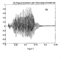
- Figure 7 is a waveform illustrating a 10 ms increase in the buffer of the system illustrated in Figure 5;
- Figure 8 is a flowchart illustrating a method according to an embodiment of the present invention.
- the playback system 100 comprises a playback element 102, a single frame buffer 104, and a play-out buffer 106.
- the play-out buffer 106 is coupled between a network (not shown) and the single frame buffer 104.
- the single frame buffer 104 is further coupled to the playback element 102.
- Incoming packets from the network are received and their content is inserted into the play-out buffer 106.
- the play-out buffer 106 provides the time delay necessary to eliminate the end-to-end delay variations of the network.
- a voice frame is periodically extracted from the play-out buffer 106 in accordance with a predefined play-out delay and inserted into the single frame buffer 104.
- the voice frame carried over the network can be in a compressed form or a direct sample-per-sample digitized representation.
- the playback element 102 recreates the original waveform.
- FIG. 200 an example of a typical original signal is illustrated generally by numeral 200.
- the signal 200 illustrates amplitude evolution over a quarter of a second of a spoken word. If the play-out buffer 106 is properly defined and there are no unexpected delays, the original signal will be reproduced as illustrated in Figure 2. However, since in reality the delays are changing constantly, the play-out buffer 106 is changing regularly.
- the play-out buffer is minimized to improve the "real-time" aspect of the system.
- the play-out buffer is changed such that a 10ms delay reduction occurs and the packets arrive faster than expected, then some packets will be dropped.
- a signal reproduced under these circumstances is illustrated generally by numeral 300. As can be seen in the reproduced signal, an adjustment occurs approximately 0.13s into the signal. Data from the original signal 200 contained in the dropped packets is missing from the reconstructed signal 300 and it can be observed that the waveform suffers from a rapid drop in the decaying overall envelope.
- a signal reproduced under these circumstances is illustrated generally by numeral 400. As can be seen in the reproduced signal, an adjustment occurs approximately 0.13s into the signal. The system waits for an incoming packet to arrive and thus it can be observed that the waveform suffers from the insertion of a gap of silence.
- an improved playback system in accordance with an embodiment of the present invention is illustrated generally by numeral 500.
- the improved system 500 includes a playback element 102, a single frame buffer 104, and a play-out buffer 106. Additionally, the improved system 500 further includes a time adjuster 502 and a specialized buffer 504.
- the proposed delay compensation improvement is an add-on to the standard set of components used in a playback system for packetized voice.
- the output of the playback element 102 is coupled to the specialized buffer 504, which is coupled to the time adjuster 502.
- the time adjuster 502 determines the rate of playback for the playback element 102.
- the specialized buffer 504 holds one or more packets of voice signal. If a delay change is limited to a single packet at a time, then the specialized buffer 504 only needs to hold a single packet of voice samples. In the present example, the specialized buffer 504 is capable of holding two packets.
- the time adjuster 502 determines the play-out rate of the playback element 102 in accordance with the amount of data in the specialized buffer 504. For example, if data in the specialized buffer 504 exceeds a first predefined threshold, the play-out rate of the playback element 102 is increased. Conversely, if data in the specialized buffer 504 falls below a second predefined threshold, the play-out rate of the playback element 102 is decreased.
- the playback element 102 itself detects the amount of data in the specialized buffer 504 and indicates to the time adjuster 502 whether to increase or decrease the play-out rate.
- the operation of the system illustrated in Figure 5 is described as follows.
- the size of the play-out buffer 106 is determined as described with reference to the prior art implementation. However, in the present embodiment, the play-out buffer 106 determines how many packets to transmit to the single element buffer 104. Under normal operation circumstances, the play-out buffer 106 transmits one packet for each predefined play-out delay. The data is decompressed, if necessary, by the playback element 102 and transmitted to the specialized buffer 504. Since there is only one packet stored in the specialized buffer 504, the playback element 102 plays out the data at a standard rate.
- the play-out buffer 106 monitors the status of arriving and departing packets and determines whether or not there is an excess accumulation of packets. This can happen, for example, if there is a reduction in the delay introduced by the play-out buffer 106 and packets arrive faster than expected.
- the play-out buffer 106 exceeds a predefined threshold, two or more packets are sent to the playback element 102 for each predefined play-out delay.
- the specialized buffer 504 holds two or more packet lengths of the signal to play-out.
- the time adjuster 502 compresses the playback time scale. By compressing the time scale, the module plays out more samples per unit time than under normal operation.
- the excess samples will have been played-out, and the play-out buffer 106 will have fallen below the predefined threshold. As a result, only one packet is sent to the playback element 102.
- the time adjuster 502 detects that there is only one packet in the specialized buffer 504 and returns to the normal time scaling.
- a signal reproduced in accordance with the current embodiment of the invention having a 10ms reduction in the delay used by the play-out buffer 106 is illustrated generally by numeral 600.
- the delay adjustment occurs at approximately 0.13s time, and the time scale is compressed by five percent over a 200ms duration. There are no visually-noticeable artifacts in the waveform 600, and listening to the sample reveals no unpleasant discontinuities.
- the playback element 102 will not receive a sufficient number of packets to cover the delay slip performed.
- the specialized buffer 504 would be empty.
- the time adjuster 502 expands the time scale. By expanding the time scale, the playback element 102 plays out fewer samples per unit time than it would under normal circumstances. After a period of time, the packets will start arriving at the expected rate, and the specialized buffer 504 will hold the normal number of packets, which in the present example is one.
- the time adjuster 502 detects that there is once again one packet of data in the specialized buffer 504 and returns to the normal time scaling.
- a signal reproduced in accordance with the current embodiment of the invention having a 10ms increase in the delay used by the play-out buffer 106 is illustrated generally by numeral 700.
- the delay adjustment occurs at approximately 0.13s time, and the time scale is expanded by five percent over a 200ms duration.
- the silence gap that was present in the prior art (see Figure 4) does not appear in this waveform, and there are no visually-noticeable artifacts. Listening to this sample reveals no unpleasant side effects.
- time adjuster 502 can be implemented in various ways. In an all-digital system, a timing adjustment can be achieved through a cascade of digital interpolation and decimation. Alternately, a timing adjustment can be achieved by adjusting the playback system clock controlling the digital-to-analog conversion.
- FIG 8 is a flowchart of a process 800 according to an embodiment of the present invention.
- packets from the network are received from the network and stored in a play-out buffer.
- the packets are transmitted to a playback element at a first rate in accordance with the number of packets in the play-out buffer.
- the packets are played out at the playback element at a second rate in accordance with the first rate of packets transmitted from the play-out buffer. Further details of this process are as described above regarding Figure 5.
Landscapes
- Engineering & Computer Science (AREA)
- Multimedia (AREA)
- Signal Processing (AREA)
- Computer Networks & Wireless Communication (AREA)
- Quality & Reliability (AREA)
- Computational Linguistics (AREA)
- Health & Medical Sciences (AREA)
- Audiology, Speech & Language Pathology (AREA)
- Human Computer Interaction (AREA)
- Physics & Mathematics (AREA)
- Acoustics & Sound (AREA)
- General Business, Economics & Management (AREA)
- Business, Economics & Management (AREA)
- Data Exchanges In Wide-Area Networks (AREA)
Abstract
Description
- The present invention relates to data streaming in packetized networks, specifically to a system and method for compensating for delay variations for continuous time signals transported over such networks.
- A packet is a unit of data that is routed between an origin and a destination on a packet-switched network, such as the Internet. In a system that uses packets, data to be transmitted is separated into packets having a predefined size. The packets are assigned an identification number and a destination address, and are transmitted over the network. Once the packets arrive at the destination, their data portions are reassembled to recreate the originally-transmitted data. However, due to a variety of end-to-end delays (such as alternate data paths, for example), the packets do not necessarily arrive in the order in which they were transmitted. Thus, the packets cannot simply be reassembled as they are received. A solution to this problem is to buffer the packets as they are received. The larger the buffer, the more leeway a packet has in arriving at its destination on time. Once the packets are received, they are then reassembled in the appropriate order in accordance with their identification number.
- In applications where continuous time signals are packetized, the packets are typically buffered at the receiving site and their play-out is delayed in order to compensate for the variations of the network end-to-end delays. As previously described, the buffer introduces an additional delay that allows the system to hold packets scheduled to be played-out later in time. Thus, it offers a time window over which the network end-to-end delay can vary. In the case of a non real-time application, such as audio or video streaming, the selected delay introduced by the buffer is, by design, typically set to a very large size. Such a large size minimizes the probability of receiving late packets.
- However, in the case of a real-time application like video conferencing or audio conversation, large delays impair the usability of the system. Large delays in real-time applications are contrary to concept of "real-time", wherein information is effectively delivered immediately. Thus it is preferable that the delay introduced by the buffer is minimized. However, having a smaller buffer increases the risk of losing packets if the delay of the packet arrival is greater than that provided by the buffer. Therefore, it has become an art to select a delay such that the probability of a late packet arrival is low enough that it is acceptable.
- In present solutions to this problem, the size of the buffer is adjusted in accordance with arrival rate of the packets. For example, if the selected delay is observed to be too small, the buffer is increased to minimize the number of late packets. Conversely, if the selected delay is observed to be too large, the buffer is decreased to make the system appear more transparent. However, a reduction in the delay can create excess packets. Similarly, an increase in the delay can create gaps in the play-out.
- Two approaches are commonly used to set the delay referred to above. Either the delay is set once for the whole session, or it is adjusted dynamically between talkspurts. A talkspurt is generally defined as a collection of packets whose data contains a continuous portion of a sound signal. In both cases, everything is done to avoid adjusting the delay during a non-silence period. It has been shown that adjusting the delay on a per-packet basis, that is, within the talkspurt, introduces gaps and slips that are damaging to the quality of the audio.
In Steinbach et al., 'Adaptive playout for low latency video streaming', International Conference on Image Processing, IEEE Vol. 1 of 3, 7 October 2001, pages 962 - 965, there is disclosed a method of adaptive media playout which adjusts the playout speed of media packets depending on channel conditions. - Therefore, there is a need for a system and method for reducing the excess discarding of packets and minimizing gaps when the play-out delay is adjusted. It is an object of the present invention to obviate or mitigate at least some of the above-mentioned disadvantages.
- In accordance with a first aspect of the present invention, there is provided a system for improving reconstruction of real-time data in a packetized network as claimed in
claim 1. In accordance with a second aspect of the present invention, there is provided a method as claimed in claim 9. - An embodiment of the invention will now be described by way of example only with reference to the following drawings in which:
- Figure 1 is block diagram of a playback system in accordance with the prior art;
- Figure 2 is a waveform of a 200 ms voice sample;
- Figure 3 is a waveform illustrating a 10 ms decrease in the buffer of the system illustrated in Figure 1;
- Figure 4 is a waveform illustrating a 10 ms increase in the buffer of the system illustrated in Figure 1;
- Figure 5 is block diagram of a playback system in accordance with an embodiment of the present invention;
- Figure 6 is a waveform illustrating a 10 ms decrease in the buffer of the system illustrated in Figure 5;
- Figure 7 is a waveform illustrating a 10 ms increase in the buffer of the system illustrated in Figure 5; and
- Figure 8 is a flowchart illustrating a method according to an embodiment of the present invention.
- For convenience, like numerals in the description refer to like structures in the drawings. Referring to Figure 1, a prior art playback system is illustrated generally by
numeral 100. Theplayback system 100 comprises aplayback element 102, asingle frame buffer 104, and a play-outbuffer 106. The play-outbuffer 106 is coupled between a network (not shown) and thesingle frame buffer 104. Thesingle frame buffer 104 is further coupled to theplayback element 102. - The operation of the system illustrated in Figure I is described as follows. Incoming packets from the network are received and their content is inserted into the play-out
buffer 106. The play-outbuffer 106 provides the time delay necessary to eliminate the end-to-end delay variations of the network. A voice frame is periodically extracted from the play-outbuffer 106 in accordance with a predefined play-out delay and inserted into thesingle frame buffer 104.
The voice frame carried over the network can be in a compressed form or a direct sample-per-sample digitized representation. Theplayback element 102 recreates the original waveform. - Referring to Figure 2, an example of a typical original signal is illustrated generally by
numeral 200. Thesignal 200 illustrates amplitude evolution over a quarter of a second of a spoken word. If the play-outbuffer 106 is properly defined and there are no unexpected delays, the original signal will be reproduced as illustrated in Figure 2. However, since in reality the delays are changing constantly, the play-outbuffer 106 is changing regularly. - As previously described, it is preferable that the play-out buffer is minimized to improve the "real-time" aspect of the system. However, if the play-out buffer is changed such that a 10ms delay reduction occurs and the packets arrive faster than expected, then some packets will be dropped. Referring to Figure 3, a signal reproduced under these circumstances is illustrated generally by
numeral 300. As can be seen in the reproduced signal, an adjustment occurs approximately 0.13s into the signal. Data from theoriginal signal 200 contained in the dropped packets is missing from the reconstructedsignal 300 and it can be observed that the waveform suffers from a rapid drop in the decaying overall envelope. - Conversely, if play-out buffer is increased to reduce the chances of dropping packets, it is possible for gaps to occur in the reproduced signal. If the play-out buffer is changed such that a 10ms delay increase occurs and the packets arrive slower than expected, the system may be required to wait for an incoming packet. Referring to Figure 4, a signal reproduced under these circumstances is illustrated generally by
numeral 400. As can be seen in the reproduced signal, an adjustment occurs approximately 0.13s into the signal. The system waits for an incoming packet to arrive and thus it can be observed that the waveform suffers from the insertion of a gap of silence. - However, it is possible to adjust the play-out delay without introducing gaps or slips by increasing or decreasing the rate at which the packets are played-out. This is achieved by selectively compressing or expanding the time scale of portions of the voice signal. If delay changes do not occur very often, then the time scale change is very small and the changes in the audio are barely detectable, if at all.
- Referring to Figure 5, an improved playback system in accordance with an embodiment of the present invention is illustrated generally by
numeral 500. Theimproved system 500 includes aplayback element 102, asingle frame buffer 104, and a play-outbuffer 106. Additionally, theimproved system 500 further includes atime adjuster 502 and aspecialized buffer 504. Thus it can be seen that the proposed delay compensation improvement is an add-on to the standard set of components used in a playback system for packetized voice. The output of theplayback element 102 is coupled to thespecialized buffer 504, which is coupled to thetime adjuster 502. Thetime adjuster 502 determines the rate of playback for theplayback element 102. - During normal steady state operation, the
specialized buffer 504 holds one or more packets of voice signal. If a delay change is limited to a single packet at a time, then thespecialized buffer 504 only needs to hold a single packet of voice samples. In the present example, thespecialized buffer 504 is capable of holding two packets. Thetime adjuster 502 determines the play-out rate of theplayback element 102 in accordance with the amount of data in thespecialized buffer 504. For example, if data in thespecialized buffer 504 exceeds a first predefined threshold, the play-out rate of theplayback element 102 is increased. Conversely, if data in thespecialized buffer 504 falls below a second predefined threshold, the play-out rate of theplayback element 102 is decreased. - In an alternate embodiment, rather than the
time adjuster 502 determining when to adjust the play-out rate, theplayback element 102 itself detects the amount of data in thespecialized buffer 504 and indicates to thetime adjuster 502 whether to increase or decrease the play-out rate. - The operation of the system illustrated in Figure 5 is described as follows. The size of the play-out
buffer 106 is determined as described with reference to the prior art implementation. However, in the present embodiment, the play-outbuffer 106 determines how many packets to transmit to thesingle element buffer 104. Under normal operation circumstances, the play-outbuffer 106 transmits one packet for each predefined play-out delay. The data is decompressed, if necessary, by theplayback element 102 and transmitted to thespecialized buffer 504. Since there is only one packet stored in thespecialized buffer 504, theplayback element 102 plays out the data at a standard rate. - The play-out
buffer 106 monitors the status of arriving and departing packets and determines whether or not there is an excess accumulation of packets. This can happen, for example, if there is a reduction in the delay introduced by the play-outbuffer 106 and packets arrive faster than expected. Once the play-outbuffer 106 exceeds a predefined threshold, two or more packets are sent to theplayback element 102 for each predefined play-out delay. As a result, thespecialized buffer 504 holds two or more packet lengths of the signal to play-out. In reaction to the extra samples inserted into thespecialized buffer 504, thetime adjuster 502 compresses the playback time scale. By compressing the time scale, the module plays out more samples per unit time than under normal operation. After a period of time, the excess samples will have been played-out, and the play-outbuffer 106 will have fallen below the predefined threshold. As a result, only one packet is sent to theplayback element 102. Thetime adjuster 502 detects that there is only one packet in thespecialized buffer 504 and returns to the normal time scaling. - Referring to Figure 6, a signal reproduced in accordance with the current embodiment of the invention having a 10ms reduction in the delay used by the play-out
buffer 106 is illustrated generally bynumeral 600. The delay adjustment occurs at approximately 0.13s time, and the time scale is compressed by five percent over a 200ms duration. There are no visually-noticeable artifacts in thewaveform 600, and listening to the sample reveals no unpleasant discontinuities. - If there is an increase in the delay of the play-out
buffer 106 and packets arrive slower than expected, theplayback element 102 will not receive a sufficient number of packets to cover the delay slip performed. This exhausts thespecialized buffer 504 of its normal amount of accumulated packets. In the present example, thespecialized buffer 504 would be empty. In reaction to the exhaustion, thetime adjuster 502 expands the time scale. By expanding the time scale, theplayback element 102 plays out fewer samples per unit time than it would under normal circumstances. After a period of time, the packets will start arriving at the expected rate, and thespecialized buffer 504 will hold the normal number of packets, which in the present example is one. Thetime adjuster 502 detects that there is once again one packet of data in thespecialized buffer 504 and returns to the normal time scaling. - Referring to Figure 7, a signal reproduced in accordance with the current embodiment of the invention having a 10ms increase in the delay used by the play-out
buffer 106 is illustrated generally bynumeral 700. The delay adjustment occurs at approximately 0.13s time, and the time scale is expanded by five percent over a 200ms duration. The silence gap that was present in the prior art (see Figure 4) does not appear in this waveform, and there are no visually-noticeable artifacts. Listening to this sample reveals no unpleasant side effects. - A person skilled in the art will appreciate that there are many methods to adjusting the play-out rate of the playback element, and thus the
time adjuster 502 need not be described in detail. Further, a person skilled in the art will appreciate that thetime adjuster 502 can be implemented in various ways. In an all-digital system, a timing adjustment can be achieved through a cascade of digital interpolation and decimation. Alternately, a timing adjustment can be achieved by adjusting the playback system clock controlling the digital-to-analog conversion. - Figure 8 is a flowchart of a
process 800 according to an embodiment of the present invention. Instep 802, packets from the network are received from the network and stored in a play-out buffer. Instep 804, the packets are transmitted to a playback element at a first rate in accordance with the number of packets in the play-out buffer. Instep 806, the packets are played out at the playback element at a second rate in accordance with the first rate of packets transmitted from the play-out buffer. Further details of this process are as described above regarding Figure 5. - Although the invention has been described with reference to certain specific embodiments, various modifications thereof will be apparent to those skilled in the art without departing from the scope of the invention as outlined in the claims appended hereto.
Claims (13)
- A system for improving reconstruction of real-time data in a packetized network, said system comprising:a play-out buffer (106) for receiving a plurality of packets from said network;a playback element (102), coupled with said play-out buffer (106), for receiving said plurality of packets from said play-out buffer (106) at a first rate in accordance with a number of packets in said play-out buffer and outputting reconstructed data for said reconstruction of said real-time data; anda time adjuster (502) for altering a second rate at which said reconstructed data is output from said playback element (102) in accordance with an availability of said plurality of packets transmitted from said play-out buffer (106) at said first rate.
- A system as defined in claim 1, wherein said time adjuster (502) increases said second rate when a number of said plurality of packets received in said play-out buffer (106) exceeds a predefined upper threshold.
- A system as defined in claim 2, wherein said time adjuster (502) returns said second rate to normal when said number of said plurality of packets falls below said predefined upper threshold.
- A system as defined in claim 1, wherein said time adjuster (502) decreases said second rate when a number of said plurality of packets received in said play-out buffer (106) falls below a lower predefined threshold.
- A system as defined in claim 4, wherein said time adjuster (502) returns said second rate to normal when said number of said plurality of packets exceeds said predefined lower threshold.
- A system as defined in claim 1, wherein said play-out buffer (106) changes a number of packets transmitted to said playback element (102) at said first rate as a number of said plurality of packets in said play-out buffer (106) changes.
- A system as defined in claim 6, wherein said play-out buffer (106) increases said number of packets transmitted to said playback element (102) at said first rate as said number of said plurality of packets in said play-out buffer (106) exceeds a predefined upper threshold.
- A system as defined in claim 6, wherein said play-out buffer (106) decreases said number of packets transmitted to said playback element (102) at said first rate as said number of said plurality of packets in said play-out buffer (106) falls below a predefined lower threshold.
- A method of improving reconstruction of real-time data in a packetized network, said method comprising the steps of:receiving a plurality of packets from said network and storing said plurality of packets in a play-out buffer (106),transmitting said plurality of packets to a playback element (102) at a first rate in accordance with a number of packets in said play-out buffer (106); andplaying out said plurality of packets at said playback element (102) at a second rate in accordance with an availability of said plurality of packets transmitted from said play-out buffer (106) at said first rate.
- A method as defined in claim 9, wherein said second rate increases when said number of packets in said play-out buffer (106) exceeds a predefined upper threshold.
- A method as defined in claim 10, where said second rate returns to normal when said number of packets in said play-out buffer (106) falls below said predefined upper threshold.
- A method as defined in claim 9, wherein said second rate decreases when said number of packets in said play-out buffer (106) falls below a predefined lower threshold.
- A method as defined in claim 12, where said second rate returns to normal when said number of said packets in said play-out buffer (106) exceeds said predefined lower threshold.
Applications Claiming Priority (3)
| Application Number | Priority Date | Filing Date | Title |
|---|---|---|---|
| CA2364091 | 2001-11-29 | ||
| CA002364091A CA2364091A1 (en) | 2001-11-29 | 2001-11-29 | System and method for compensating packet voice delay variations |
| PCT/US2002/038034 WO2003048900A2 (en) | 2001-11-29 | 2002-11-27 | System and method for compensating packet delay variations |
Publications (3)
| Publication Number | Publication Date |
|---|---|
| EP1449378A2 EP1449378A2 (en) | 2004-08-25 |
| EP1449378A4 EP1449378A4 (en) | 2005-05-18 |
| EP1449378B1 true EP1449378B1 (en) | 2007-01-10 |
Family
ID=4170703
Family Applications (1)
| Application Number | Title | Priority Date | Filing Date |
|---|---|---|---|
| EP02784627A Expired - Lifetime EP1449378B1 (en) | 2001-11-29 | 2002-11-27 | System and method for compensating packet delay variations |
Country Status (7)
| Country | Link |
|---|---|
| US (1) | US7366193B2 (en) |
| EP (1) | EP1449378B1 (en) |
| CN (1) | CN100512423C (en) |
| AU (1) | AU2002346558A1 (en) |
| CA (1) | CA2364091A1 (en) |
| DE (1) | DE60217538D1 (en) |
| WO (1) | WO2003048900A2 (en) |
Families Citing this family (13)
| Publication number | Priority date | Publication date | Assignee | Title |
|---|---|---|---|---|
| US7596488B2 (en) * | 2003-09-15 | 2009-09-29 | Microsoft Corporation | System and method for real-time jitter control and packet-loss concealment in an audio signal |
| US8718452B2 (en) | 2004-07-20 | 2014-05-06 | Panasonic Corporation | Stream data reception/reproduction device and stream data reception/reproduction method |
| US20060104223A1 (en) * | 2004-11-12 | 2006-05-18 | Arnaud Glatron | System and method to create synchronized environment for audio streams |
| US20060168114A1 (en) * | 2004-11-12 | 2006-07-27 | Arnaud Glatron | Audio processing system |
| US8755675B2 (en) * | 2006-04-20 | 2014-06-17 | Texas Instruments Incorporated | Flexible and efficient memory utilization for high bandwidth receivers, integrated circuits, systems, methods and processes of manufacture |
| ITTO20060668A1 (en) | 2006-09-19 | 2008-03-20 | Rai Radiotelevisione Italiana Spa | METHOD TO REPRODUCE AN AUDIO AND / OR VIDEO SEQUENCE, REPRODUCTION DEVICE AND REPRODUCTION DEVICE THAT USES IT |
| US8160112B2 (en) * | 2007-09-17 | 2012-04-17 | Cisco Technology, Inc. | Buffering a media stream |
| US7895629B1 (en) * | 2007-11-07 | 2011-02-22 | At&T Mobility Ii Llc | Video service buffer management in a mobile rate control enabled network |
| JP5664229B2 (en) * | 2010-12-28 | 2015-02-04 | ソニー株式会社 | Transmission device, transmission method, and program |
| CA2767700A1 (en) * | 2011-02-11 | 2012-08-11 | Research In Motion Limited | Apparatus, and associated method, by which to play out media data pursuant to a media data service |
| EP3671281A1 (en) * | 2018-12-21 | 2020-06-24 | European Space Agency | Method and system for processing a gnss signal using homomorphic encryption |
| US20230059063A1 (en) * | 2020-02-04 | 2023-02-23 | Dolby International Ab | Method and device for adaptive playout of media content |
| US11190457B2 (en) * | 2020-02-19 | 2021-11-30 | At&T Intellectual Property I, L.P. | Selectively bypassing a routing queue in a routing device in a fifth generation (5G) or other next generation network |
Family Cites Families (7)
| Publication number | Priority date | Publication date | Assignee | Title |
|---|---|---|---|---|
| AUPN786896A0 (en) * | 1996-02-02 | 1996-02-29 | Telstra Corporation Limited | A network fault system |
| US6172972B1 (en) * | 1996-05-28 | 2001-01-09 | Microsoft Corporation | Multi-packet transport structure and method for sending network data over satellite network |
| US5875175A (en) * | 1997-05-01 | 1999-02-23 | 3Com Corporation | Method and apparatus for time-based download control |
| US6252851B1 (en) * | 1997-03-27 | 2001-06-26 | Massachusetts Institute Of Technology | Method for regulating TCP flow over heterogeneous networks |
| US6259677B1 (en) * | 1998-09-30 | 2001-07-10 | Cisco Technology, Inc. | Clock synchronization and dynamic jitter management for voice over IP and real-time data |
| US6389032B1 (en) * | 1999-02-11 | 2002-05-14 | International Business Machines Corporation | Internet voice transmission |
| US7047308B2 (en) * | 2001-08-31 | 2006-05-16 | Sharp Laboratories Of America, Inc. | System and method for simultaneous media playout |
-
2001
- 2001-11-29 CA CA002364091A patent/CA2364091A1/en not_active Abandoned
-
2002
- 2002-11-27 EP EP02784627A patent/EP1449378B1/en not_active Expired - Lifetime
- 2002-11-27 US US10/308,990 patent/US7366193B2/en active Active
- 2002-11-27 AU AU2002346558A patent/AU2002346558A1/en not_active Abandoned
- 2002-11-27 WO PCT/US2002/038034 patent/WO2003048900A2/en active IP Right Grant
- 2002-11-27 CN CN02826643.9A patent/CN100512423C/en not_active Expired - Fee Related
- 2002-11-27 DE DE60217538T patent/DE60217538D1/en not_active Expired - Lifetime
Also Published As
| Publication number | Publication date |
|---|---|
| US20030235217A1 (en) | 2003-12-25 |
| CA2364091A1 (en) | 2003-05-29 |
| DE60217538D1 (en) | 2007-02-22 |
| WO2003048900A2 (en) | 2003-06-12 |
| EP1449378A4 (en) | 2005-05-18 |
| CN100512423C (en) | 2009-07-08 |
| AU2002346558A8 (en) | 2003-06-17 |
| US7366193B2 (en) | 2008-04-29 |
| EP1449378A2 (en) | 2004-08-25 |
| WO2003048900A3 (en) | 2003-12-18 |
| CN1613256A (en) | 2005-05-04 |
| AU2002346558A1 (en) | 2003-06-17 |
Similar Documents
| Publication | Publication Date | Title |
|---|---|---|
| EP1183681B1 (en) | Sub-packet insertion for packet loss compensation in voice over ip networks | |
| EP1449378B1 (en) | System and method for compensating packet delay variations | |
| US7079486B2 (en) | Adaptive threshold based jitter buffer management for packetized data | |
| US6370125B1 (en) | Dynamic delay compensation for packet-based voice network | |
| US8520519B2 (en) | External jitter buffer in a packet voice system | |
| EP1696628A2 (en) | A system and method for modifying speech playout to compensate for transmission delay jitter in a voice over Internet Protocol (VolP) network | |
| US7787500B2 (en) | Packet receiving method and device | |
| WO1995022233A1 (en) | Method of dynamically compensating for variable transmission delays in packet networks | |
| JP4782973B2 (en) | Audio and video signal synchronization | |
| JP2002505048A (en) | Two-way video communication over packet data network | |
| EP1845691B1 (en) | Media stream relay device and method | |
| JPH0411059B2 (en) | ||
| JPH09191296A (en) | Method and equipment for synchronizing clock for digital decoder and digital coder | |
| US7783482B2 (en) | Method and apparatus for enhancing voice intelligibility in voice-over-IP network applications with late arriving packets | |
| US6775301B1 (en) | System and method for compensating for channel jitter | |
| US6721825B1 (en) | Method to control data reception buffers for packetized voice channels | |
| EP1340344B1 (en) | Latency management for a network | |
| JP2004264497A (en) | Voice decoding device | |
| CA2468768A1 (en) | System and method for compensating packet delay variations | |
| JP3449276B2 (en) | Packet receiving apparatus, packet receiving method, and recording medium | |
| JP3659183B2 (en) | Real-time packet delay buffer control method | |
| KR100685982B1 (en) | Method and apparatus for synchronization of media information | |
| JP2001251342A (en) | Packet receiver |
Legal Events
| Date | Code | Title | Description |
|---|---|---|---|
| PUAI | Public reference made under article 153(3) epc to a published international application that has entered the european phase |
Free format text: ORIGINAL CODE: 0009012 |
|
| 17P | Request for examination filed |
Effective date: 20040602 |
|
| AK | Designated contracting states |
Kind code of ref document: A2 Designated state(s): AT BE BG CH CY CZ DE DK EE ES FI FR GB GR IE IT LI LU MC NL PT SE SK TR |
|
| AX | Request for extension of the european patent |
Extension state: AL LT LV MK RO SI |
|
| A4 | Supplementary search report drawn up and despatched |
Effective date: 20050406 |
|
| RIC1 | Information provided on ipc code assigned before grant |
Ipc: 7H 04L 29/06 B Ipc: 7H 04N 7/173 A |
|
| RAP1 | Party data changed (applicant data changed or rights of an application transferred) |
Owner name: CIENA CORPORATION |
|
| GRAP | Despatch of communication of intention to grant a patent |
Free format text: ORIGINAL CODE: EPIDOSNIGR1 |
|
| RTI1 | Title (correction) |
Free format text: SYSTEM AND METHOD FOR COMPENSATING PACKET DELAY VARIATIONS |
|
| GRAS | Grant fee paid |
Free format text: ORIGINAL CODE: EPIDOSNIGR3 |
|
| GRAA | (expected) grant |
Free format text: ORIGINAL CODE: 0009210 |
|
| AK | Designated contracting states |
Kind code of ref document: B1 Designated state(s): AT BE BG CH CY CZ DE DK EE ES FI FR GB GR IE IT LI LU MC NL PT SE SK TR |
|
| PG25 | Lapsed in a contracting state [announced via postgrant information from national office to epo] |
Ref country code: FI Free format text: LAPSE BECAUSE OF FAILURE TO SUBMIT A TRANSLATION OF THE DESCRIPTION OR TO PAY THE FEE WITHIN THE PRESCRIBED TIME-LIMIT Effective date: 20070110 Ref country code: NL Free format text: LAPSE BECAUSE OF FAILURE TO SUBMIT A TRANSLATION OF THE DESCRIPTION OR TO PAY THE FEE WITHIN THE PRESCRIBED TIME-LIMIT Effective date: 20070110 Ref country code: DK Free format text: LAPSE BECAUSE OF FAILURE TO SUBMIT A TRANSLATION OF THE DESCRIPTION OR TO PAY THE FEE WITHIN THE PRESCRIBED TIME-LIMIT Effective date: 20070110 Ref country code: AT Free format text: LAPSE BECAUSE OF FAILURE TO SUBMIT A TRANSLATION OF THE DESCRIPTION OR TO PAY THE FEE WITHIN THE PRESCRIBED TIME-LIMIT Effective date: 20070110 Ref country code: CH Free format text: LAPSE BECAUSE OF FAILURE TO SUBMIT A TRANSLATION OF THE DESCRIPTION OR TO PAY THE FEE WITHIN THE PRESCRIBED TIME-LIMIT Effective date: 20070110 Ref country code: LI Free format text: LAPSE BECAUSE OF FAILURE TO SUBMIT A TRANSLATION OF THE DESCRIPTION OR TO PAY THE FEE WITHIN THE PRESCRIBED TIME-LIMIT Effective date: 20070110 |
|
| REG | Reference to a national code |
Ref country code: GB Ref legal event code: FG4D |
|
| REG | Reference to a national code |
Ref country code: IE Ref legal event code: FG4D |
|
| REF | Corresponds to: |
Ref document number: 60217538 Country of ref document: DE Date of ref document: 20070222 Kind code of ref document: P |
|
| PG25 | Lapsed in a contracting state [announced via postgrant information from national office to epo] |
Ref country code: SE Free format text: LAPSE BECAUSE OF FAILURE TO SUBMIT A TRANSLATION OF THE DESCRIPTION OR TO PAY THE FEE WITHIN THE PRESCRIBED TIME-LIMIT Effective date: 20070410 |
|
| PG25 | Lapsed in a contracting state [announced via postgrant information from national office to epo] |
Ref country code: BG Free format text: LAPSE BECAUSE OF THE APPLICANT RENOUNCES Effective date: 20070411 |
|
| PG25 | Lapsed in a contracting state [announced via postgrant information from national office to epo] |
Ref country code: ES Free format text: LAPSE BECAUSE OF FAILURE TO SUBMIT A TRANSLATION OF THE DESCRIPTION OR TO PAY THE FEE WITHIN THE PRESCRIBED TIME-LIMIT Effective date: 20070421 |
|
| PG25 | Lapsed in a contracting state [announced via postgrant information from national office to epo] |
Ref country code: PT Free format text: LAPSE BECAUSE OF FAILURE TO SUBMIT A TRANSLATION OF THE DESCRIPTION OR TO PAY THE FEE WITHIN THE PRESCRIBED TIME-LIMIT Effective date: 20070611 |
|
| NLV1 | Nl: lapsed or annulled due to failure to fulfill the requirements of art. 29p and 29m of the patents act | ||
| REG | Reference to a national code |
Ref country code: CH Ref legal event code: PL |
|
| EN | Fr: translation not filed | ||
| PLBE | No opposition filed within time limit |
Free format text: ORIGINAL CODE: 0009261 |
|
| STAA | Information on the status of an ep patent application or granted ep patent |
Free format text: STATUS: NO OPPOSITION FILED WITHIN TIME LIMIT |
|
| PG25 | Lapsed in a contracting state [announced via postgrant information from national office to epo] |
Ref country code: SK Free format text: LAPSE BECAUSE OF FAILURE TO SUBMIT A TRANSLATION OF THE DESCRIPTION OR TO PAY THE FEE WITHIN THE PRESCRIBED TIME-LIMIT Effective date: 20070110 |
|
| 26N | No opposition filed |
Effective date: 20071011 |
|
| PG25 | Lapsed in a contracting state [announced via postgrant information from national office to epo] |
Ref country code: CZ Free format text: LAPSE BECAUSE OF FAILURE TO SUBMIT A TRANSLATION OF THE DESCRIPTION OR TO PAY THE FEE WITHIN THE PRESCRIBED TIME-LIMIT Effective date: 20070110 Ref country code: BE Free format text: LAPSE BECAUSE OF FAILURE TO SUBMIT A TRANSLATION OF THE DESCRIPTION OR TO PAY THE FEE WITHIN THE PRESCRIBED TIME-LIMIT Effective date: 20070110 |
|
| PG25 | Lapsed in a contracting state [announced via postgrant information from national office to epo] |
Ref country code: DE Free format text: LAPSE BECAUSE OF FAILURE TO SUBMIT A TRANSLATION OF THE DESCRIPTION OR TO PAY THE FEE WITHIN THE PRESCRIBED TIME-LIMIT Effective date: 20070411 |
|
| PG25 | Lapsed in a contracting state [announced via postgrant information from national office to epo] |
Ref country code: GR Free format text: LAPSE BECAUSE OF FAILURE TO SUBMIT A TRANSLATION OF THE DESCRIPTION OR TO PAY THE FEE WITHIN THE PRESCRIBED TIME-LIMIT Effective date: 20070411 Ref country code: IT Free format text: LAPSE BECAUSE OF FAILURE TO SUBMIT A TRANSLATION OF THE DESCRIPTION OR TO PAY THE FEE WITHIN THE PRESCRIBED TIME-LIMIT Effective date: 20070110 Ref country code: FR Free format text: LAPSE BECAUSE OF FAILURE TO SUBMIT A TRANSLATION OF THE DESCRIPTION OR TO PAY THE FEE WITHIN THE PRESCRIBED TIME-LIMIT Effective date: 20070831 |
|
| PG25 | Lapsed in a contracting state [announced via postgrant information from national office to epo] |
Ref country code: MC Free format text: LAPSE BECAUSE OF NON-PAYMENT OF DUE FEES Effective date: 20071130 |
|
| PG25 | Lapsed in a contracting state [announced via postgrant information from national office to epo] |
Ref country code: IE Free format text: LAPSE BECAUSE OF NON-PAYMENT OF DUE FEES Effective date: 20071127 |
|
| PG25 | Lapsed in a contracting state [announced via postgrant information from national office to epo] |
Ref country code: FR Free format text: LAPSE BECAUSE OF FAILURE TO SUBMIT A TRANSLATION OF THE DESCRIPTION OR TO PAY THE FEE WITHIN THE PRESCRIBED TIME-LIMIT Effective date: 20070110 |
|
| PG25 | Lapsed in a contracting state [announced via postgrant information from national office to epo] |
Ref country code: EE Free format text: LAPSE BECAUSE OF FAILURE TO SUBMIT A TRANSLATION OF THE DESCRIPTION OR TO PAY THE FEE WITHIN THE PRESCRIBED TIME-LIMIT Effective date: 20070110 |
|
| PGFP | Annual fee paid to national office [announced via postgrant information from national office to epo] |
Ref country code: GB Payment date: 20081126 Year of fee payment: 7 |
|
| PG25 | Lapsed in a contracting state [announced via postgrant information from national office to epo] |
Ref country code: CY Free format text: LAPSE BECAUSE OF FAILURE TO SUBMIT A TRANSLATION OF THE DESCRIPTION OR TO PAY THE FEE WITHIN THE PRESCRIBED TIME-LIMIT Effective date: 20070110 |
|
| PG25 | Lapsed in a contracting state [announced via postgrant information from national office to epo] |
Ref country code: LU Free format text: LAPSE BECAUSE OF NON-PAYMENT OF DUE FEES Effective date: 20071127 |
|
| PG25 | Lapsed in a contracting state [announced via postgrant information from national office to epo] |
Ref country code: TR Free format text: LAPSE BECAUSE OF FAILURE TO SUBMIT A TRANSLATION OF THE DESCRIPTION OR TO PAY THE FEE WITHIN THE PRESCRIBED TIME-LIMIT Effective date: 20070110 |
|
| GBPC | Gb: european patent ceased through non-payment of renewal fee |
Effective date: 20091127 |
|
| PG25 | Lapsed in a contracting state [announced via postgrant information from national office to epo] |
Ref country code: GB Free format text: LAPSE BECAUSE OF NON-PAYMENT OF DUE FEES Effective date: 20091127 |