EP1448883B1 - Noise attenuator arrangement - Google Patents
Noise attenuator arrangement Download PDFInfo
- Publication number
- EP1448883B1 EP1448883B1 EP02777575A EP02777575A EP1448883B1 EP 1448883 B1 EP1448883 B1 EP 1448883B1 EP 02777575 A EP02777575 A EP 02777575A EP 02777575 A EP02777575 A EP 02777575A EP 1448883 B1 EP1448883 B1 EP 1448883B1
- Authority
- EP
- European Patent Office
- Prior art keywords
- valve
- air
- attenuator
- attenuator member
- central region
- Prior art date
- Legal status (The legal status is an assumption and is not a legal conclusion. Google has not performed a legal analysis and makes no representation as to the accuracy of the status listed.)
- Expired - Lifetime
Links
- 239000012530 fluid Substances 0.000 claims abstract 4
- 239000006262 metallic foam Substances 0.000 claims description 13
- 238000011144 upstream manufacturing Methods 0.000 claims description 3
- 230000002093 peripheral effect Effects 0.000 claims description 2
- SGPGESCZOCHFCL-UHFFFAOYSA-N Tilisolol hydrochloride Chemical compound [Cl-].C1=CC=C2C(=O)N(C)C=C(OCC(O)C[NH2+]C(C)(C)C)C2=C1 SGPGESCZOCHFCL-UHFFFAOYSA-N 0.000 claims 1
- 239000006260 foam Substances 0.000 description 11
- 239000011148 porous material Substances 0.000 description 7
- 239000002184 metal Substances 0.000 description 4
- 238000007789 sealing Methods 0.000 description 3
- 241000239290 Araneae Species 0.000 description 2
- 238000003491 array Methods 0.000 description 2
- 230000000694 effects Effects 0.000 description 2
- 238000005057 refrigeration Methods 0.000 description 2
- 239000004744 fabric Substances 0.000 description 1
- 239000000835 fiber Substances 0.000 description 1
- 239000000463 material Substances 0.000 description 1
- 239000004033 plastic Substances 0.000 description 1
- 229920003023 plastic Polymers 0.000 description 1
Images


Classifications
-
- F—MECHANICAL ENGINEERING; LIGHTING; HEATING; WEAPONS; BLASTING
- F02—COMBUSTION ENGINES; HOT-GAS OR COMBUSTION-PRODUCT ENGINE PLANTS
- F02K—JET-PROPULSION PLANTS
- F02K1/00—Plants characterised by the form or arrangement of the jet pipe or nozzle; Jet pipes or nozzles peculiar thereto
- F02K1/28—Plants characterised by the form or arrangement of the jet pipe or nozzle; Jet pipes or nozzles peculiar thereto using fluid jets to influence the jet flow
- F02K1/34—Plants characterised by the form or arrangement of the jet pipe or nozzle; Jet pipes or nozzles peculiar thereto using fluid jets to influence the jet flow for attenuating noise
-
- F—MECHANICAL ENGINEERING; LIGHTING; HEATING; WEAPONS; BLASTING
- F01—MACHINES OR ENGINES IN GENERAL; ENGINE PLANTS IN GENERAL; STEAM ENGINES
- F01D—NON-POSITIVE DISPLACEMENT MACHINES OR ENGINES, e.g. STEAM TURBINES
- F01D17/00—Regulating or controlling by varying flow
- F01D17/10—Final actuators
- F01D17/105—Final actuators by passing part of the fluid
-
- F—MECHANICAL ENGINEERING; LIGHTING; HEATING; WEAPONS; BLASTING
- F05—INDEXING SCHEMES RELATING TO ENGINES OR PUMPS IN VARIOUS SUBCLASSES OF CLASSES F01-F04
- F05D—INDEXING SCHEME FOR ASPECTS RELATING TO NON-POSITIVE-DISPLACEMENT MACHINES OR ENGINES, GAS-TURBINES OR JET-PROPULSION PLANTS
- F05D2220/00—Application
- F05D2220/30—Application in turbines
- F05D2220/36—Application in turbines specially adapted for the fan of turbofan engines
Definitions
- This invention relates to an attenuator for reducing noise associated with an air bleed system particularly, but not exdusively, for a turbofan aircraft engine.
- a servo-controlled valve can be provided in ducting leading from the compressor casing to the fan by-pass duct. Normally, there would be an array of several bleed valves spaced around the axis of the engine. Also, two or more valves cr valve arrays may be provided at different stages of the compressor. The different valves or valve arrays are opened and dosed, or sometimes modulated, i.e. set to give a required flow rate between on and off by an engine management system. The valves are controlled by this system along with other engine parameters to optimise the operation of the engine for different aperating conditions.
- Patent application number GB2,132,269A discloses an attenuator for a gas turbine engine air bleed valve.
- the attenuator receives the plume of high pressure air from a compressor stage of the engine and has a large number of small holes which convert the stream to a multiplicity of air jets.
- Patent application number GB 878 480 discloses a dome like body with grooves for the release of flow gas there through where said grooves are all of the same size.
- Patent application number EP0354161A3 discloses a muffler plate for a refrigeration system compressor with a few relatively large holes arranged round a check valve.
- US patent number 5,906.225 shows a refrigeration system expansion valve with an elongate attenuator member made of porous material.
- an air bleed system for a turbofan aircraft engine comprising duct means for receiving air from a compressor stage of the engine and directing said air to a bypass duct of the engine valve means within the duct means for controlling the flow of said air, and a sound attenuator member extending over the duct means downstream and having apertures distributed over the member for passing said air, characterised in that the apertures of the attenuator member are arranged for the distribution of the air passing through the attenuator member to be relatively more restricted in a central region of the member than in another region outside said central region.
- Said another region is an annular region extending round said central region.
- valve and attenuator member are constructed for the pressure drop from the upstream to the downstream side of the valve member to be substantially equal to the pressure drop through the attenuator member.
- the attenuator member may be positioned for a high pressure stream of air from the valve to impinge upon said central region.
- the attenuator member comprises a substantial number of relatively small perforations distributed over a peripheral region of the attenuator member and no or relatively few such apertures in the central region.
- the attenuator member has apertures differentially distributed over the attenuator member and porous material adjacent at least some of the apertures.
- the porosity of the porous material may be different in different regions of the attenuator member.
- the attenuator member may comprise porous material for defining said apertures, the porosity of the porous material being different in different regions of the attenuator member.
- the porous material may be porous metallic foam.
- the valve may be a bullet valve.
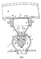
- an air bleed arrangement for a high-bypass turbofan aircraft engine may comprise duct means 1 leading from the compressor casing 2 to the engine casing 3.
- the duct means includes the body 4 of a "bullet-type" air bleed valve. It is called a “bullet-type” valve because it comprises a valve member 6 having a portion 7 which generally smoothly reduces in diameter in the direction facing the flow of the air from the compressor casing 2 through the valve 4.
- the valve member 6 is mounted on a shaft 8 that is supported by bearings 9 held in respective spiders 10.
- the spiders 10 are fixed to the ducting 5 above the valve member 6.
- the valve member 6 is hollow with the top carrying a sealing ring 11. Inside the sealing ring there is a spring 12.
- valve member 6 is normally pushed by air pressure against the spring 12 so that the periphery 13 of the member 6 engages a matching sealing portion 14 of the valve body 4. This closes the valve 4.
- a counter pressure is applied to the interior of the valve member.
- the ducting 5 leads to a hat shaped attenuator member 16, the top of which is provided with a large number of small holes 17.
- the holes might have a diameter of 1.6 mm and there might be around 1500 of them evenly distributed over an annular region 18 around the top of the member 16. However, there are no holes in the central region 19 of the member 16. It is in this central region 19 that the jet or plume of air from the valve impinges.
- valve 4 and the member 16 are constructed and dimensioned so that the pressure drop across the valve, i.e. from the upstream to the downstream side of the valve member 6 is about equal to the pressure drop across the attenuator member 16.
- FIG 3 there is shown another embodiment of the bleed arrangement in which the top of the hat-shaped attenuator 16 is provided with a cover member 29 that has relatively few holes, for example eight outer holes 31, a single central hole 32, and eight intermediate holes 33, between the central one and the eight outer ones.
- the central hole 32 and the intermediate holes 33 are about the same size, and smaller than, the outer holes 31.
- the holes 31, 32 and 33 provide substantially unrestricted flow of the air from the valve 4 but, just beneath the top of the member 16, there is a layer 35 of metallic foam providing tortuous paths through the attenuator and tending to even out the distribution of the flow of air from the bleed valve.
- the foam 35 could comprise Retimet (trade mark) metal foam.
- the valve 4 need not be a bullet-type valve; instead it could be a sleeve valve or the like.
- the invention includes an attenuator 16 in which the central hole 32 is absent.
- FIG. 4 to 6 there is shown a number of alternative layouts of holes in the cover 29 of the attenuator 16.
- the size, shape and positioning of the holes 31, 32, 33 may be changed to suit different flow-rates of air.
- a Retimet foam layer 35 may be provided beneath the member 16.
- the cover 29 of the attenuator 16 is omitted and effectively replaced entirely by a self supporting layer of Retimet foam layer 35.
- the metal foam 35 could incorporate different grades of foam; for example, the centre area 32 could be of a grade more restrictive to flow than the outer area.
- Foams are graded with a number system representing the number of pores/cells per linear inch; e.g. 80 grade has 80 cells per inch. It is expected that the range of foams suitable for this application would be in the range 5 to 150 grade, and preferably be in the range 10 to 80 grade.
- a sandwich structure of layers of foam of different grades would alternate a wider range of noise frequencies and provide improved noise reduction. Also, by using foams of different thickness one could also change the noise reduction properties by changing the flow rate. This needs to be balanced against the desired flow rate from the valve 6 and the pressure drop across the valve 6.
- the layer of metallic foam 35 of Figures 3 to 6 may have different zones of different porosity aligned with selected holes 31, 32, 33 in the cover 29.
- the inserts of metallic foam 35 of Figure 7 can have a different porosity for different zones. In this way, one can accommodate different airflow rates or different levels of sound attenuation for different applications and thus provide greater flexibility in the design of the characteristics of the attenuator.
- layer 35 of metallic foam shown in Figures 3 to 6 may be replaced by individual inserts of metallic foam that are secured in each of the holes 31, 32, 33.
- a mat of metal or other fibres may be used to produce a similar effect to the metal foam to control flow rate and pressure drop across the valve 6 to reduce noise.
- a mat could be a woven or non-woven fibre structure or fabric.
- the cover 29 might be required or desirable in some of those applications where a foam metal layer is used, for example, to restrict air flow more in some areas than in other areas. But in other applications the cover 29 may not be needed. Where a cover 29 is used it may be of any support structure such as perforated metal or plastics material or could simply comprise two mutually orthogonal sets of parallel wires or wire mesh to retain the foam metal layer 35 in place.
Landscapes
- Engineering & Computer Science (AREA)
- Mechanical Engineering (AREA)
- General Engineering & Computer Science (AREA)
- Chemical & Material Sciences (AREA)
- Combustion & Propulsion (AREA)
- Soundproofing, Sound Blocking, And Sound Damping (AREA)
- Details Of Valves (AREA)
- Structures Of Non-Positive Displacement Pumps (AREA)
- Vehicle Interior And Exterior Ornaments, Soundproofing, And Insulation (AREA)
- Lighters Containing Fuel (AREA)
- Non-Reversible Transmitting Devices (AREA)
- Diaphragms For Electromechanical Transducers (AREA)
- Mattresses And Other Support Structures For Chairs And Beds (AREA)
Abstract
Description
Claims (10)
- An air bleed system for a turbofan aircraft engine, the system comprising duct means (1, 5) for receiving air from a compressor stage of the engine and directing said air to a bypass duct (20) of the engine valve means (4, 6) within the duct means for controlling the flow of said air, and a sound attenuator member (16) extending over the duct means downstream and having apertures (17, 31, 32, 33) distributed over the member for passing paid air, characterised in that the apertures of the attenuator member (16) are arranged for the distribution of the air passing through the attenuator member to be relatively more restricted in a central region (19) of the member than in another region (18) outside said central region.
- A system according to daim 1, wherein said another region is an annular region extending round said central region.
- A system according to claim 1 or claim 2, wherein the valve (4) and attenuator member are constructed for the pressure drop from the upstream to the downstream side of the valve member (6) to be substantially equal to the pressure drop through the attenuator member.
- A system according to claim 1, 2 or 3, wherein the attenuator member is positioned for a high pressure stream of air from the valve to impinge upon said central region.
- A system according to claim 1, 2, 3 or 4, wherein the attenuator member comprises a substantial number of relatively small perforations (17) distributed over a peripheral region of the attenuator member and no or relatively few such apertures in the central region (19).
- Apparatus according to claim 1 or claim 2, wherein the member (16) comprises a layer of metallic foam (35) through which the pressurised fluid may pass.
- Apparatus according to claim 2, wherein metallic foam inserts (35) are provided in at least some of the holes (17, 31, 32, 33) in the attenuator member (16).
- Apparatus according to claim 2 or claim 4, wherein the metallic foam (35) has different zones of different porosity.
- Apparatus according to claim 3, wherein selected insets (35) have a different porosity compared with other inserts.
- Apparatus according to any preceding claim, wherein the valve is a bullet valve.
Applications Claiming Priority (5)
| Application Number | Priority Date | Filing Date | Title |
|---|---|---|---|
| GB0127952A GB0127952D0 (en) | 2001-11-21 | 2001-11-21 | Attenuator arrangement |
| GB0127952 | 2001-11-21 | ||
| GB0209371A GB0209371D0 (en) | 2002-04-24 | 2002-04-24 | Attenuator arrangement |
| GB0209371 | 2002-04-24 | ||
| PCT/GB2002/005230 WO2003046358A1 (en) | 2001-11-21 | 2002-11-20 | Noise attenuator arrangement |
Publications (3)
| Publication Number | Publication Date |
|---|---|
| EP1448883A1 EP1448883A1 (en) | 2004-08-25 |
| EP1448883B1 true EP1448883B1 (en) | 2005-08-17 |
| EP1448883B8 EP1448883B8 (en) | 2005-10-05 |
Family
ID=26246792
Family Applications (1)
| Application Number | Title | Priority Date | Filing Date |
|---|---|---|---|
| EP02777575A Expired - Lifetime EP1448883B8 (en) | 2001-11-21 | 2002-11-20 | Noise attenuator arrangement |
Country Status (7)
| Country | Link |
|---|---|
| US (1) | US20050067218A1 (en) |
| EP (1) | EP1448883B8 (en) |
| AT (1) | ATE302339T1 (en) |
| AU (1) | AU2002339198A1 (en) |
| CA (1) | CA2468141A1 (en) |
| DE (1) | DE60205653D1 (en) |
| WO (1) | WO2003046358A1 (en) |
Families Citing this family (39)
| Publication number | Priority date | Publication date | Assignee | Title |
|---|---|---|---|---|
| SE525812C2 (en) * | 2002-06-12 | 2005-05-03 | Saab Ab | Acoustic lining, use of a lining and ways of producing an acoustic lining |
| US8079441B2 (en) * | 2002-09-08 | 2011-12-20 | Guobiao Zhang | Muffler |
| CN1408990B (en) * | 2002-09-08 | 2012-04-25 | 章国标 | silencer |
| GB2405666A (en) * | 2003-09-05 | 2005-03-09 | Dunlop Aerospace Ltd | Noise attenuator, eg for turbofan engine air bleed system |
| DE202005011448U1 (en) * | 2005-07-18 | 2006-11-23 | Kess, Roland | Silencer outlet part for a motorcycle silencer |
| US7387489B2 (en) | 2005-10-17 | 2008-06-17 | Honeywell International Inc. | Bleed valve outlet flow deflector |
| GB0614360D0 (en) * | 2006-07-20 | 2006-08-30 | Rolls Royce Plc | Aeroengine bleed valve |
| GB0616847D0 (en) * | 2006-08-25 | 2006-10-04 | Rolls Royce Plc | Aeroengine bleed valve |
| US7797945B2 (en) | 2006-09-06 | 2010-09-21 | Honeywell International Inc. | Bleed valve outlet flow deflector |
| GB2443418B (en) * | 2006-11-02 | 2011-05-04 | Rolls Royce Plc | An acoustic arrangement |
| DE102006061733A1 (en) * | 2006-12-28 | 2008-07-03 | Robert Bosch Gmbh | Retaining device for retaining of reducing agent-dosing valve, has internal space for retaining reducing agent-dosing valve, and sound damping device, which absorbs sound waves that come out from internal space |
| US20090126194A1 (en) * | 2007-11-21 | 2009-05-21 | Honeywell International, Inc. | Noise attenuators and methods of manufacturing noise attenuators and bleed valve assemblies |
| GB0820598D0 (en) * | 2008-11-11 | 2008-12-17 | Rolls Royce Plc | A noise reduction device |
| GB0820597D0 (en) * | 2008-11-11 | 2008-12-17 | Rolls Royce Plc | A noise reduction device |
| GB0912171D0 (en) * | 2009-07-14 | 2009-08-26 | Rolls Royce Plc | A flow discharge device |
| US8328741B2 (en) | 2009-09-29 | 2012-12-11 | Covidien Lp | Pneumatic compression garment with noise attenuating means |
| US8469910B2 (en) | 2009-09-29 | 2013-06-25 | Covidien Lp | Pneumatic compression garment with noise attenuating means |
| US9572720B2 (en) | 2009-09-29 | 2017-02-21 | Covidien Lp | Reduced noise pneumatic compression garment |
| GB0922425D0 (en) * | 2009-12-23 | 2010-02-03 | Rolls Royce Plc | Bleed assembly for a gas turbine engine |
| DE102010027587A1 (en) * | 2010-07-19 | 2012-01-19 | Rolls-Royce Deutschland Ltd & Co Kg | Bleed air outlet in the bypass duct of a turbofan engine |
| DE102010031855A1 (en) * | 2010-07-22 | 2012-01-26 | J. Eberspächer GmbH & Co. KG | exhaust system |
| US8430202B1 (en) * | 2011-12-28 | 2013-04-30 | General Electric Company | Compact high-pressure exhaust muffling devices |
| US9399951B2 (en) | 2012-04-17 | 2016-07-26 | General Electric Company | Modular louver system |
| US8511096B1 (en) | 2012-04-17 | 2013-08-20 | General Electric Company | High bleed flow muffling system |
| US8550208B1 (en) | 2012-04-23 | 2013-10-08 | General Electric Company | High pressure muffling devices |
| GB201322832D0 (en) * | 2013-12-23 | 2014-02-12 | Rolls Royce Plc | A flow outlet |
| CN105736181A (en) * | 2014-12-09 | 2016-07-06 | 上海新力动力设备研究所 | Annular porous flow disturbing structure of gas flow adjusting device of solid rocket engine |
| FR3044705B1 (en) * | 2015-12-07 | 2019-11-01 | Safran Aircraft Engines | SYSTEM FOR DISCHARGING A COMPRESSOR FLOW OF A TURBOMACHINE |
| US10215193B2 (en) * | 2017-01-31 | 2019-02-26 | Meggitt Aerospace Ltd. | Valve assembly |
| KR102463454B1 (en) * | 2017-12-01 | 2022-11-04 | 현대자동차주식회사 | Silencer for clutch air booster |
| US11432995B2 (en) | 2018-08-29 | 2022-09-06 | Leggett & Platt Canada Co. | Pneumatic massage |
| US11883358B2 (en) | 2018-03-05 | 2024-01-30 | Leggett & Platt Canada Co. | Pneumatic massage system |
| US11039975B2 (en) | 2018-08-29 | 2021-06-22 | Leggett & Platt Canada Co. | Pneumatic massage |
| US11078842B2 (en) * | 2019-03-26 | 2021-08-03 | Raytheon Technologies Corporation | Exhaust distribution manifold |
| EP4110649A1 (en) | 2020-02-24 | 2023-01-04 | Schukra Berndorf GmbH | Pneumatic bladder arrangement for a seat and method for manufacturing the same |
| US11560968B2 (en) * | 2020-02-27 | 2023-01-24 | Honeywell International Inc. | Bleed valve with reduced noise |
| FR3109179B1 (en) * | 2020-04-10 | 2023-05-12 | Safran Aircraft Engines | Optimized discharge duct grid and optimized discharge valve |
| FR3109177B1 (en) * | 2020-04-10 | 2023-05-12 | Safran Aircraft Engines | Herringbone discharge duct grille. |
| US11970969B2 (en) * | 2022-06-29 | 2024-04-30 | General Electric Company | Compressor bypass bleed system for a ducted fan engine |
Family Cites Families (11)
| Publication number | Priority date | Publication date | Assignee | Title |
|---|---|---|---|---|
| US4537277A (en) * | 1982-12-03 | 1985-08-27 | The Secretary Of State For Defence In Her Britannic Majesty's Government Of The United Kingdom Of Great Britain And Northern Ireland | Silencer for high velocity gas flow |
| HU196649B (en) * | 1984-05-22 | 1988-12-28 | Autoipari Kutato Fejlesztoe | Silencer advantageously for reducing the noise of blow-off valves |
| US4913260A (en) * | 1988-01-11 | 1990-04-03 | Tenneco Inc. | Gas silencing system with controlling sound attenuation |
| FR2628477B1 (en) * | 1988-03-11 | 1993-05-14 | Bertin & Cie | EJECTOR OR INJECTOR MUFFLER FOR THE EXPANSION OF A GASEOUS FLUID AND BLOWING DEVICE PROVIDED WITH AN ASSEMBLY OF SUCH A MUFFLER |
| US4904165A (en) * | 1988-08-02 | 1990-02-27 | Carrier Corporation | Muffler/check valve assembly for scroll compressor |
| US5923003A (en) * | 1996-09-09 | 1999-07-13 | Northrop Grumman Corporation | Extended reaction acoustic liner for jet engines and the like |
| US5906225A (en) * | 1997-09-10 | 1999-05-25 | General Motors Corporation | Orifice tube type refrigerant expansion valve assembly with combined particulate and noise attenuation filters |
| US6089346A (en) * | 1999-06-02 | 2000-07-18 | 3M Innovative Properties Company | Muffler with acoustic barrier material for limited clearance pneumatic device applications |
| US6343672B1 (en) * | 2000-03-23 | 2002-02-05 | Nova Gas Transmission Ltd. | Blowdown and venting jet noise suppressor |
| US20030047216A1 (en) * | 2001-09-07 | 2003-03-13 | Kelly Paul A. | Pop-type pressure relief valve |
| US6898934B1 (en) * | 2003-11-18 | 2005-05-31 | Daimlerchrysler Corporation | External blow off conversion of compressor recirculation valve |
-
2002
- 2002-11-20 AT AT02777575T patent/ATE302339T1/en not_active IP Right Cessation
- 2002-11-20 AU AU2002339198A patent/AU2002339198A1/en not_active Abandoned
- 2002-11-20 DE DE60205653T patent/DE60205653D1/en not_active Expired - Lifetime
- 2002-11-20 EP EP02777575A patent/EP1448883B8/en not_active Expired - Lifetime
- 2002-11-20 US US10/496,165 patent/US20050067218A1/en not_active Abandoned
- 2002-11-20 WO PCT/GB2002/005230 patent/WO2003046358A1/en not_active Ceased
- 2002-11-20 CA CA002468141A patent/CA2468141A1/en not_active Abandoned
Also Published As
| Publication number | Publication date |
|---|---|
| DE60205653D1 (en) | 2005-09-22 |
| ATE302339T1 (en) | 2005-09-15 |
| AU2002339198A1 (en) | 2003-06-10 |
| EP1448883A1 (en) | 2004-08-25 |
| EP1448883B8 (en) | 2005-10-05 |
| US20050067218A1 (en) | 2005-03-31 |
| CA2468141A1 (en) | 2003-06-05 |
| WO2003046358A1 (en) | 2003-06-05 |
Similar Documents
| Publication | Publication Date | Title |
|---|---|---|
| EP1448883A1 (en) | Noise attenuator arrangement | |
| US7331421B2 (en) | Flow restrictors for aircraft inlet acoustic treatments, and associated systems and methods | |
| US6571910B2 (en) | Method and apparatus for improved noise attenuation in a dissipative internal combustion engine exhaust muffler | |
| CN113785113A (en) | Integration of a fan flutter damper in an engine housing | |
| US4979587A (en) | Jet engine noise suppressor | |
| JP2022543721A (en) | Valve silencer and electronic expansion valve having this valve silencer | |
| CA2601387C (en) | Noise abatement module using herschel-quincke tubes | |
| CN107438881B (en) | Acoustic lining and methods of constructing acoustic lining | |
| EP1629234A1 (en) | Noise reducing combustor | |
| US10677163B2 (en) | Noise attenuation structures | |
| CA2659617A1 (en) | Fluid pressure reduction device for high pressure-drop ratios | |
| CN108291554B (en) | System for discharging compressor flow of turbine engine | |
| JP4066417B2 (en) | Compressor air outflow system | |
| KR20140109821A (en) | Sound attenuator of an exhaust gas turbocharger | |
| GB2056563A (en) | Pneumatic exhaust | |
| WO2005024187A1 (en) | Noise attenuation for an air bleed valve of a turbofan engine | |
| CA2552675C (en) | Fluid trim apparatus and method | |
| WO2000009923A1 (en) | A fluid pressure reduction valve | |
| EP0487163A1 (en) | Improved pressure reduction valve for gas | |
| US11873763B2 (en) | Optimised discharge line grid and optimized discharge valve | |
| CN115516195B (en) | Acoustically optimized exhaust line grid with channels | |
| JPH11173644A (en) | Air conditioning facility | |
| JPS6025702B2 (en) | Gaseous fluid flow control device | |
| JPH09125908A (en) | Exhaust chamber for steam turbine | |
| HK1102973B (en) | Fluid trim apparatus and method |
Legal Events
| Date | Code | Title | Description |
|---|---|---|---|
| PUAI | Public reference made under article 153(3) epc to a published international application that has entered the european phase |
Free format text: ORIGINAL CODE: 0009012 |
|
| 17P | Request for examination filed |
Effective date: 20040618 |
|
| AK | Designated contracting states |
Kind code of ref document: A1 Designated state(s): AT BE BG CH CY CZ DE DK EE ES FI FR GB GR IE IT LI LU MC NL PT SE SK TR |
|
| AX | Request for extension of the european patent |
Extension state: AL LT LV MK RO SI |
|
| GRAP | Despatch of communication of intention to grant a patent |
Free format text: ORIGINAL CODE: EPIDOSNIGR1 |
|
| GRAS | Grant fee paid |
Free format text: ORIGINAL CODE: EPIDOSNIGR3 |
|
| GRAA | (expected) grant |
Free format text: ORIGINAL CODE: 0009210 |
|
| AK | Designated contracting states |
Kind code of ref document: B1 Designated state(s): AT BE BG CH CY CZ DE DK EE ES FI FR GB GR IE IT LI LU MC NL PT SE SK TR |
|
| PG25 | Lapsed in a contracting state [announced via postgrant information from national office to epo] |
Ref country code: CZ Free format text: LAPSE BECAUSE OF FAILURE TO SUBMIT A TRANSLATION OF THE DESCRIPTION OR TO PAY THE FEE WITHIN THE PRESCRIBED TIME-LIMIT Effective date: 20050817 Ref country code: FI Free format text: LAPSE BECAUSE OF FAILURE TO SUBMIT A TRANSLATION OF THE DESCRIPTION OR TO PAY THE FEE WITHIN THE PRESCRIBED TIME-LIMIT Effective date: 20050817 Ref country code: TR Free format text: LAPSE BECAUSE OF FAILURE TO SUBMIT A TRANSLATION OF THE DESCRIPTION OR TO PAY THE FEE WITHIN THE PRESCRIBED TIME-LIMIT Effective date: 20050817 Ref country code: SK Free format text: LAPSE BECAUSE OF FAILURE TO SUBMIT A TRANSLATION OF THE DESCRIPTION OR TO PAY THE FEE WITHIN THE PRESCRIBED TIME-LIMIT Effective date: 20050817 Ref country code: EE Free format text: LAPSE BECAUSE OF FAILURE TO SUBMIT A TRANSLATION OF THE DESCRIPTION OR TO PAY THE FEE WITHIN THE PRESCRIBED TIME-LIMIT Effective date: 20050817 Ref country code: CH Free format text: LAPSE BECAUSE OF FAILURE TO SUBMIT A TRANSLATION OF THE DESCRIPTION OR TO PAY THE FEE WITHIN THE PRESCRIBED TIME-LIMIT Effective date: 20050817 Ref country code: NL Free format text: LAPSE BECAUSE OF FAILURE TO SUBMIT A TRANSLATION OF THE DESCRIPTION OR TO PAY THE FEE WITHIN THE PRESCRIBED TIME-LIMIT Effective date: 20050817 Ref country code: BE Free format text: LAPSE BECAUSE OF FAILURE TO SUBMIT A TRANSLATION OF THE DESCRIPTION OR TO PAY THE FEE WITHIN THE PRESCRIBED TIME-LIMIT Effective date: 20050817 Ref country code: AT Free format text: LAPSE BECAUSE OF FAILURE TO SUBMIT A TRANSLATION OF THE DESCRIPTION OR TO PAY THE FEE WITHIN THE PRESCRIBED TIME-LIMIT Effective date: 20050817 Ref country code: LI Free format text: LAPSE BECAUSE OF FAILURE TO SUBMIT A TRANSLATION OF THE DESCRIPTION OR TO PAY THE FEE WITHIN THE PRESCRIBED TIME-LIMIT Effective date: 20050817 Ref country code: IT Free format text: LAPSE BECAUSE OF FAILURE TO SUBMIT A TRANSLATION OF THE DESCRIPTION OR TO PAY THE FEE WITHIN THE PRESCRIBED TIME-LIMIT;WARNING: LAPSES OF ITALIAN PATENTS WITH EFFECTIVE DATE BEFORE 2007 MAY HAVE OCCURRED AT ANY TIME BEFORE 2007. THE CORRECT EFFECTIVE DATE MAY BE DIFFERENT FROM THE ONE RECORDED. Effective date: 20050817 |
|
| REG | Reference to a national code |
Ref country code: GB Ref legal event code: FG4D |
|
| REG | Reference to a national code |
Ref country code: CH Ref legal event code: EP |
|
| RIN2 | Information on inventor provided after grant (corrected) |
Inventor name: HILLYER DARREN Inventor name: BRISTOW, ANDREW,DUNLOP AEROSPACE LIMITED Inventor name: YEOMANS, KEVIN |
|
| REG | Reference to a national code |
Ref country code: IE Ref legal event code: FG4D |
|
| REF | Corresponds to: |
Ref document number: 60205653 Country of ref document: DE Date of ref document: 20050922 Kind code of ref document: P |
|
| PG25 | Lapsed in a contracting state [announced via postgrant information from national office to epo] |
Ref country code: GR Free format text: LAPSE BECAUSE OF FAILURE TO SUBMIT A TRANSLATION OF THE DESCRIPTION OR TO PAY THE FEE WITHIN THE PRESCRIBED TIME-LIMIT Effective date: 20051117 Ref country code: SE Free format text: LAPSE BECAUSE OF FAILURE TO SUBMIT A TRANSLATION OF THE DESCRIPTION OR TO PAY THE FEE WITHIN THE PRESCRIBED TIME-LIMIT Effective date: 20051117 Ref country code: BG Free format text: LAPSE BECAUSE OF FAILURE TO SUBMIT A TRANSLATION OF THE DESCRIPTION OR TO PAY THE FEE WITHIN THE PRESCRIBED TIME-LIMIT Effective date: 20051117 Ref country code: DK Free format text: LAPSE BECAUSE OF FAILURE TO SUBMIT A TRANSLATION OF THE DESCRIPTION OR TO PAY THE FEE WITHIN THE PRESCRIBED TIME-LIMIT Effective date: 20051117 |
|
| PG25 | Lapsed in a contracting state [announced via postgrant information from national office to epo] |
Ref country code: DE Free format text: LAPSE BECAUSE OF FAILURE TO SUBMIT A TRANSLATION OF THE DESCRIPTION OR TO PAY THE FEE WITHIN THE PRESCRIBED TIME-LIMIT Effective date: 20051118 |
|
| PG25 | Lapsed in a contracting state [announced via postgrant information from national office to epo] |
Ref country code: CY Free format text: LAPSE BECAUSE OF FAILURE TO SUBMIT A TRANSLATION OF THE DESCRIPTION OR TO PAY THE FEE WITHIN THE PRESCRIBED TIME-LIMIT Effective date: 20051120 |
|
| PG25 | Lapsed in a contracting state [announced via postgrant information from national office to epo] |
Ref country code: IE Free format text: LAPSE BECAUSE OF NON-PAYMENT OF DUE FEES Effective date: 20051121 |
|
| PG25 | Lapsed in a contracting state [announced via postgrant information from national office to epo] |
Ref country code: ES Free format text: LAPSE BECAUSE OF FAILURE TO SUBMIT A TRANSLATION OF THE DESCRIPTION OR TO PAY THE FEE WITHIN THE PRESCRIBED TIME-LIMIT Effective date: 20051128 |
|
| PG25 | Lapsed in a contracting state [announced via postgrant information from national office to epo] |
Ref country code: MC Free format text: LAPSE BECAUSE OF NON-PAYMENT OF DUE FEES Effective date: 20051130 Ref country code: LU Free format text: LAPSE BECAUSE OF NON-PAYMENT OF DUE FEES Effective date: 20051130 |
|
| PG25 | Lapsed in a contracting state [announced via postgrant information from national office to epo] |
Ref country code: PT Free format text: LAPSE BECAUSE OF FAILURE TO SUBMIT A TRANSLATION OF THE DESCRIPTION OR TO PAY THE FEE WITHIN THE PRESCRIBED TIME-LIMIT Effective date: 20060117 |
|
| NLV1 | Nl: lapsed or annulled due to failure to fulfill the requirements of art. 29p and 29m of the patents act | ||
| REG | Reference to a national code |
Ref country code: CH Ref legal event code: PL |
|
| PLBE | No opposition filed within time limit |
Free format text: ORIGINAL CODE: 0009261 |
|
| STAA | Information on the status of an ep patent application or granted ep patent |
Free format text: STATUS: NO OPPOSITION FILED WITHIN TIME LIMIT |
|
| 26N | No opposition filed |
Effective date: 20060518 |
|
| PG25 | Lapsed in a contracting state [announced via postgrant information from national office to epo] |
Ref country code: FR Free format text: LAPSE BECAUSE OF FAILURE TO SUBMIT A TRANSLATION OF THE DESCRIPTION OR TO PAY THE FEE WITHIN THE PRESCRIBED TIME-LIMIT Effective date: 20060818 |
|
| REG | Reference to a national code |
Ref country code: IE Ref legal event code: MM4A |
|
| EN | Fr: translation not filed | ||
| GBPC | Gb: european patent ceased through non-payment of renewal fee |
Effective date: 20061120 |
|
| PG25 | Lapsed in a contracting state [announced via postgrant information from national office to epo] |
Ref country code: GB Free format text: LAPSE BECAUSE OF NON-PAYMENT OF DUE FEES Effective date: 20061120 |
|
| PG25 | Lapsed in a contracting state [announced via postgrant information from national office to epo] |
Ref country code: FR Free format text: LAPSE BECAUSE OF FAILURE TO SUBMIT A TRANSLATION OF THE DESCRIPTION OR TO PAY THE FEE WITHIN THE PRESCRIBED TIME-LIMIT Effective date: 20050817 |