EP1448416B1 - Fahrzeugdatenbussystem mit sensormodul - Google Patents
Fahrzeugdatenbussystem mit sensormodul Download PDFInfo
- Publication number
- EP1448416B1 EP1448416B1 EP02803363A EP02803363A EP1448416B1 EP 1448416 B1 EP1448416 B1 EP 1448416B1 EP 02803363 A EP02803363 A EP 02803363A EP 02803363 A EP02803363 A EP 02803363A EP 1448416 B1 EP1448416 B1 EP 1448416B1
- Authority
- EP
- European Patent Office
- Prior art keywords
- data
- bus
- data bus
- rotational speed
- vehicle
- Prior art date
- Legal status (The legal status is an assumption and is not a legal conclusion. Google has not performed a legal analysis and makes no representation as to the accuracy of the status listed.)
- Expired - Lifetime
Links
- 238000012937 correction Methods 0.000 claims description 21
- 230000001133 acceleration Effects 0.000 claims description 13
- 230000005540 biological transmission Effects 0.000 claims description 13
- 238000007781 pre-processing Methods 0.000 claims description 7
- 230000010354 integration Effects 0.000 claims description 6
- 238000001914 filtration Methods 0.000 claims description 5
- 238000012935 Averaging Methods 0.000 claims description 4
- 230000007774 longterm Effects 0.000 claims description 4
- 238000005070 sampling Methods 0.000 description 5
- 238000011156 evaluation Methods 0.000 description 4
- 230000008878 coupling Effects 0.000 description 3
- 238000010168 coupling process Methods 0.000 description 3
- 238000005859 coupling reaction Methods 0.000 description 3
- 239000000725 suspension Substances 0.000 description 3
- 238000004364 calculation method Methods 0.000 description 1
- 230000008859 change Effects 0.000 description 1
- 125000004122 cyclic group Chemical group 0.000 description 1
- 230000001419 dependent effect Effects 0.000 description 1
- 238000013461 design Methods 0.000 description 1
- 238000011161 development Methods 0.000 description 1
- 230000018109 developmental process Effects 0.000 description 1
- 230000004069 differentiation Effects 0.000 description 1
- 230000000694 effects Effects 0.000 description 1
- 230000006855 networking Effects 0.000 description 1
- 230000002277 temperature effect Effects 0.000 description 1
- 238000012546 transfer Methods 0.000 description 1
Images
Classifications
-
- G—PHYSICS
- G01—MEASURING; TESTING
- G01C—MEASURING DISTANCES, LEVELS OR BEARINGS; SURVEYING; NAVIGATION; GYROSCOPIC INSTRUMENTS; PHOTOGRAMMETRY OR VIDEOGRAMMETRY
- G01C21/00—Navigation; Navigational instruments not provided for in groups G01C1/00 - G01C19/00
- G01C21/26—Navigation; Navigational instruments not provided for in groups G01C1/00 - G01C19/00 specially adapted for navigation in a road network
- G01C21/28—Navigation; Navigational instruments not provided for in groups G01C1/00 - G01C19/00 specially adapted for navigation in a road network with correlation of data from several navigational instruments
-
- G—PHYSICS
- G01—MEASURING; TESTING
- G01C—MEASURING DISTANCES, LEVELS OR BEARINGS; SURVEYING; NAVIGATION; GYROSCOPIC INSTRUMENTS; PHOTOGRAMMETRY OR VIDEOGRAMMETRY
- G01C25/00—Manufacturing, calibrating, cleaning, or repairing instruments or devices referred to in the other groups of this subclass
-
- B—PERFORMING OPERATIONS; TRANSPORTING
- B60—VEHICLES IN GENERAL
- B60T—VEHICLE BRAKE CONTROL SYSTEMS OR PARTS THEREOF; BRAKE CONTROL SYSTEMS OR PARTS THEREOF, IN GENERAL; ARRANGEMENT OF BRAKING ELEMENTS ON VEHICLES IN GENERAL; PORTABLE DEVICES FOR PREVENTING UNWANTED MOVEMENT OF VEHICLES; VEHICLE MODIFICATIONS TO FACILITATE COOLING OF BRAKES
- B60T2250/00—Monitoring, detecting, estimating vehicle conditions
- B60T2250/06—Sensor zero-point adjustment; Offset compensation
-
- B—PERFORMING OPERATIONS; TRANSPORTING
- B60—VEHICLES IN GENERAL
- B60T—VEHICLE BRAKE CONTROL SYSTEMS OR PARTS THEREOF; BRAKE CONTROL SYSTEMS OR PARTS THEREOF, IN GENERAL; ARRANGEMENT OF BRAKING ELEMENTS ON VEHICLES IN GENERAL; PORTABLE DEVICES FOR PREVENTING UNWANTED MOVEMENT OF VEHICLES; VEHICLE MODIFICATIONS TO FACILITATE COOLING OF BRAKES
- B60T2250/00—Monitoring, detecting, estimating vehicle conditions
- B60T2250/06—Sensor zero-point adjustment; Offset compensation
- B60T2250/062—Sensor zero-point adjustment; Offset compensation loosing zero-point calibration of yaw rate sensors when travelling on banked roads or in case of temperature variations
Definitions
- the invention relates to a vehicle data bus system with sensor module according to the preamble of claims 1 and 2.
- a sensor module with data bus connection is known. At least two sensors for detecting vehicle movements of the vehicle and an evaluation unit for preprocessing and offset correction of the sensor data signals are spatially combined in a sensor module in the sensor module.
- the sensors are longitudinal acceleration sensors, lateral acceleration sensors and / or yaw rate sensors.
- the sensor data is provided by the sensor module vehicle dynamics / wheel slip control systems, brake control systems, steering control systems, suspension control systems and engine management control systems.
- the sensor module outputs rotation rate sensor data in the form of rotation angle data, rotational angular velocity data, rotational angular acceleration data onto a CAN (Controller Area Network) data bus.
- the preprocessing of the sensor data signals is performed, which includes an oversampling, integration and filtering.
- the evaluation of the sensor module also caused by temperature effects effects are compensated.
- a comparable arrangement is known from DE 42 28 893 A1.
- a vehicle data bus system with a locating module is known as a bus subscriber.
- the locating module comprises at least one GPS receiver and evaluation means.
- the locating module is configured to receive rotation rate data via the data bus from a vehicle dynamics / wheel slip control system and to obtain location data.
- the location module is further able to output acquired location data on the data bus.
- DE 100 08 550 A1 and EP 940 654 A1 disclose vehicle data bus systems with a data bus, a sensor module embodied as a bus subscriber with a yaw rate sensor and a vehicle dynamics / wheel slip control system designed as a bus subscriber, configured to receive offset corrected yaw rate data over the data bus.
- WO 01/20575 A1 moreover shows a location module with means for bus-side reception of gyro data of a vehicle dynamics / wheel slip control system.
- the object of the invention is to provide a vehicle data bus system of the type mentioned, which provides comparatively diverse and flexible yaw rate data available.
- the invention solves this problem by providing a vehicle data bus system with the features of claims 1 and 2.
- the dependent claims relate to advantageous embodiments and further developments of the invention.
- the vehicle data bus system has at least one driving dynamics / wheel slip control system, a sensor module and a further bus subscriber as bus subscribers in data transmission connection with one another.
- the sensor module comprises at least one rotation rate sensor and a unit for preprocessing the rotation rate sensor signals.
- the preprocessing of the rotation rate sensor signals comprises, for. As a sampling of the signals, an averaging and / or integration, a low-pass filtering. The sampling is advantageously carried out as oversampling in relation to the transmission rate of the data bus.
- the data bus used z. B. be a CAN bus, the navigation system, vehicle dynamics / Radschlupfregelsysteme, brake control systems, steering control systems, suspension control systems and / or engine management control systems and other bus subscribers with each other.
- the preprocessed rotation rate data is output from the sensor module to the data bus.
- the vehicle dynamics / wheel slip control system receives the preprocessed angular rate data via the data bus and carries out an offset correction of the z. B. temperature-related zero shift of the sensor data.
- the vehicle dynamics / wheel slip control system estimates the offset in the short-term range using further data, eg. B. wheel speed data with forward / reverse direction data and / or lateral acceleration data.
- At least one further bus participant receives the preprocessed rotation rate data via the data bus and carries out an offset correction by.
- information may be available that allows it to perform offset correction as well.
- the vehicle dynamics / wheel slip control system is capable of calculating wheel path information by using wheel speed and forward / reverse direction data received over the data bus from the wheel sensors and outputting the bike path information in the form of wheel-individual wheel pulse counters to the data bus.
- Rad impulses stand for a certain distance traveled.
- the number of wheel pulses in the vehicle dynamics / wheel slip control system is added up and the summed sum is transmitted in a data bus message, a cyclical overflow of the value being made when a maximum value is reached.
- This type of transmission of Radwegde offers particular advantages, since in case of loss of a message on the data bus with receipt of the next message anyway the Radweginformation exists.
- the driving dynamics / wheel slip control system and / or the further bus user can access already offset-corrected rotation rate data.
- An advantageous realization of the offset correction in the sensor module provides that by means of the received over the data bus Wheel speed data and / or forward / backward direction data and / or lateral acceleration data in the vehicle dynamics / Radschlupfregelsystem the offset is calculated and transmitted to the data bus.
- the sensor module receives the offset data via the data bus.
- the offset correction is performed and offset-corrected rotation rate data is output to the data bus.
- the vehicle dynamics / wheel slip control system and / or the further bus subscriber carry out the offset correction.
- the vehicle dynamics / wheel slip control system and / or the further bus subscriber carry out the offset correction.
- the vehicle dynamics / wheel slip control system is connected to the at least one further bus subscriber via a first data bus.
- This first data bus is z. B. a CAN data bus with high transfer rate, via the networking of the vehicle dynamics / Radschlupfregelsysteme, brake control systems, steering control systems, suspension control systems and / or engine management control systems takes place in the vehicle.
- the connection to the sensor module is via a second data bus, the z. B. can be provided exclusively for the connection between the sensor module and vehicle dynamics / Radschlupfregelsystem.
- the vehicle dynamics / wheel slip control system is designed to receive pre-processed wire rate data from the sensor module via the second data bus. It is further configured to output the offset-corrected yaw rate data to the first data bus. Above the first data bus can then the other bus participants receive the offset-corrected rotation rate data.
- the vehicle dynamics / wheel slip control system is capable of calculating offset data by using the wheel speed received and the forward / reverse direction data received over the first data bus, and detecting the just preprocessed yaw rate data on the first data bus in offset corrected yaw rate data received over the second data bus issue.
- the rotation rate data comprise various data which can be obtained from the rotation rate data by simple or multiple integration or differentiation, that is also rotation angle data, rotational angular velocities and / or rotational angular acceleration data.
- the transmission of the angle of rotation as the already integrated rate of rotation over the data bus or the data buses offers particular advantages, since in case of loss of a message on the data bus with receipt of the next message, the angle of rotation of the vehicle still exists. Simply transmitting the spin rate would result in an error, since the change contained in the lost message is ignored.
- the rotation rate is integrated into the rotation angle and transmitted in a data bus message, with a cyclic overflow of the integrator of 359.99 ° to 0 ° or vice versa, depending on the direction of rotation.
- the sensor module in addition to the rotation rate sensor comprises a longitudinal acceleration sensor and / or a lateral acceleration sensor.
- the sensor data of these sensors are preprocessed in the sensor module analogous to the sensor data of the rotation rate sensor and output to the data bus.
- the at least one further bus subscriber has a navigation system an integrated location function or a separate location module.
- the navigation system and the locating module performs an offset correction in the long-term range with the aid of the digital map and / or the last traveled route and / or GPS.
- the navigation system can match the direction of travel of the vehicle obtained from the rotation rate data of the sensor module with the direction of travel obtained from the digital map.
- the navigation system and / or the locating module can make an offset correction in the long-term range by matching the direction of travel of the vehicle obtained from the rotation rate data of the sensor module with the last distance covered.
- An advantageous application of the rotation rate data is the use for the coupling location for navigation purposes.
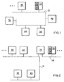
- the vehicle data bus system with the data bus 10 the driving dynamics / wheel slip control system 20, the sensor module 30 with rotation rate sensor 32 and lateral acceleration sensor 34, the positioning module 40, the navigation module 50, the wheel sensors 60 and the steering angle sensor 70 is shown schematically.
- the sensor module 30 there is an oversampling of the rotation rate sensor 32, wherein the sampling is to be understood as oversampling in relation to the transmission rate of the data bus 10.
- the averaging and low-pass filtering of the signal of the rotation rate sensor 32 is output to the data bus 10.
- the offset correction is performed.
- One or more of the bus participants driving dynamics / Radschlupfregelsystem 20, locating module 40 and / or navigation module 50, which perform the offset correction are optionally adapted to output in turn the offset-corrected rotation rate data on the data bus 10.
- the sensor module 30 is capable of performing offset correction itself.
- the zero shift, d. H. the offset calculated and transmitted via the data bus 10 to the sensor module 30.
- the offset correction 30 is then carried out in the sensor module 30 and the offset-corrected rotation rate data are output by the sensor module 30 to the data bus 10.
- the vehicle dynamics / wheel slip control system 20 can also output rotation rates that are integrated into the data bus 10 for integrated rotation rates.
- the preprocessed and offset-corrected rate of rotation is integrated and output to the data bus 10, wherein the integration value of 359.99 ° to 0 ° or vice versa - depending on the direction of rotation of the vehicle - overflows.
- the angle of rotation corresponds to the relative direction of travel, as z. B. for navigation purposes to the coupling location application.
- the relative direction of travel is expressed in a message together with the wheel speed data which includes the direction of travel, and / or the Radwegdes and / or the steering angle transmitted.
- FIG. 2 schematically shows another example of the vehicle data bus system with the first data bus 12 and the second data bus 14.
- the driving dynamics / wheel slip control system 20 is in data transmission connection with the positioning module 40, the navigation module 50, the wheel sensors 60 and the steering angle sensor 70.
- the driving dynamics / wheel slip control system 20 is in data transmission connection with the sensor module 30 with yaw rate sensor 32 and lateral acceleration sensor 34.
- a sampling of the rotation rate sensor 32 takes place in the sensor module 30.
- the sampling ensues as oversampling in relation to the transmission rate of the data bus 14.
- the averaging and low-pass filtering of the signal of the rotation rate sensor 32 takes place in the sensor module 30.
- the thus-processed yaw rate signal is output to the data bus 14.
- the vehicle dynamics / wheel slip control system 20 receives the preprocessed yaw rate data via the data bus 14 and corrects the temperature point related zero offset of the yaw rate sensor, ie, performs the offset correction.
- the vehicle dynamics / wheel slip control system 20 is optionally configured to output the offset-corrected yaw rate data to the data bus 12 or the data bus 14.
- the vehicle dynamics / wheel slip control system 20 may alternatively or additionally also output the preprocessed rotation rate data received via the second data bus 14 to the first data bus 12 so that the compensation of the temperature point-related zero shift of the rotation rate sensor, ie the offset correction, then occurs in the location module 40 and / or in the navigation module 50 , can be done.
- the locating module 40 and / or the navigation module 50 are then optionally arranged thereon, in turn output the offset-corrected yaw rate data to the data bus 12.
- the sensor module 30 is capable of performing offset correction itself.
- the zero shift, d. H. the offset calculated and sent via the data bus 14 to the sensor module 30.
- the offset correction is then carried out and the offset-corrected angular rate data are output from the sensor module 30 to the data bus 14.
- the vehicle dynamics / wheel slip control system 20 may output the offset corrected yaw rate data received over the data bus 14 to the data bus 12 and / or reconstruct the preprocessed yaw rate data using the offset and output it to the data bus 12.
- the vehicle dynamics / wheel slip control system 20 can also output to the data bus 12 integrated yaw rates for the rotational angle.
- the preprocessed and offset-corrected rate of rotation is integrated and output to the data bus 12, wherein the integration value of 359.99 ° to 0 ° or vice versa - depending on the direction of rotation of the vehicle - overflows.
- the angle of rotation corresponds to the relative direction of travel, as z. B. for navigation purposes to the coupling location application.
- the relative direction of travel in a message is transmitted together with the wheel speed data that includes the direction of travel and / or the Radwega and / or the steering angle.
- the sensor module 30 can output to the rotation angle integrated rotation rate on the data bus 14.
- the overflow occurs analogously to the calculation in the vehicle dynamics / wheel slip control system 20.
- the relative direction of travel via the data bus 14 is transmitted to the vehicle dynamics / Radschlupfregelsystem 20 and output from there to the data bus 12.
- the message for this advantageously comprises wheel speed data that includes the direction of travel and / or the bike path information and / or the steering angle.
- the bus architectures shown in FIG. 1 and FIG. 2 are to be understood as examples. There are also various other bus architectures conceivable for realizing the invention.
- So z. B. the bus participants via one or more buses, z. B. CAN (Controller Area Network) with high transmission speed and / or LIN, be connected, alternatively or additionally, for.
- the connection of the buses with each other then takes place depending on the degree of protocol implementation z. B. via a router, a bridge or a gateway.
Landscapes
- Engineering & Computer Science (AREA)
- Radar, Positioning & Navigation (AREA)
- Remote Sensing (AREA)
- Physics & Mathematics (AREA)
- General Physics & Mathematics (AREA)
- Automation & Control Theory (AREA)
- Manufacturing & Machinery (AREA)
- Steering Control In Accordance With Driving Conditions (AREA)
- Regulating Braking Force (AREA)
- Navigation (AREA)
Description
- Die Erfindung betrifft ein Fahrzeugdatenbussystem mit Sensormodul gemäß dem Oberbegriff der Ansprüche 1 und 2.
- Aus der WO 99/47889 ist ein Sensormodul mit Datenbusanschluss bekannt. In dem Sensormodul werden mindestens zwei Sensoren zur Erfassung von Fahrzeugbewegungen des Fahrzeugs und eine Auswerteeinheit zur Vorverarbeitung und Offsetkorrektur der Sensordatensignale räumlich in einem Sensormodul zusammengefasst. Die Sensoren sind Längsbeschleunigungssensoren, Querbeschleunigungssensoren und/oder Drehratensensoren. Die Sensordaten werden vom Sensormodul Fahrdynamik-/Radschlupfregelsystemen, Bremsregelsystemen, Lenkregelsystemen, Fahrwerkregelsystemen und Motormanagementregelsystemen zur Verfügung gestellt. Das Sensormodul gibt Drehratensensordaten in Form von Drehwinkeldaten, Drehwinkelgeschwindigkeitsdaten, Drehwinkelbeschleunigungsdaten auf einen CAN-Datenbus (CAN: Controller Area Network) aus. In der Auswerteeinheit des Sensormoduls wird die Vorverarbeitung der Sensordatensignale durchgeführt, die eine Überabtastung, Integration und Filterung umfasst. In der Auswerteeinheit des Sensormoduls werden außerdem durch Temperatureinflüsse bedingte Effekte kompensiert. Eine vergleichbare Anordnung ist aus der DE 42 28 893 A1 bekannt.
- In der DE 199 44 177 A1 ist ein Fahrzeugdatenbussystem mit einem Ortungsmodul als Busteilnehmer bekannt. Das Ortungsmodul umfasst dabei zumindest einen GPS-Empfänger und Auswertemittel. Das Ortungsmodul ist darauf eingerichtet, Drehratendaten über den Datenbus von einem Fahrdynamik-/Radschlupfregelsystem zu empfangen und Ortungsdaten zu gewinnen. Das Ortungsmodul ist weiter in der Lage, gewonnene Ortungsdaten auf den Datenbus auszugeben.
- Die DE 100 08 550 A1 und die EP 940 654 A1 offenbaren Fahrzeugdatenbussysteme mit einem Datenbus, einem als Busteilnehmer ausgebildeten Sensormodul mit einem Drehratensensor und einem als Busteilnehmer ausgebildeten Fahrdynamik-/Radschlupfregelsystem, das zum Empfangen von offsetkorrigierten Drehratendaten über den Datenbus ausgebildet ist. Die WO 01/20575 A1 zeigt darüber hinaus ein Ortungsmodul mit Mitteln zum busseitigen Empfang von Gyrodaten eines Fahrdynamik-/Radschlupfregelsystems.
- Aufgabe der Erfindung ist es, ein Fahrzeugdatenbussystem der eingangs genannten Art zu schaffen, das vergleichsweise vielfältig und flexibel nutzbare Drehratendaten zur Verfügung stellt.
- Die Erfindung löst diese Aufgabe durch die Bereitstellung eines Fahrzeugdatenbussystems mit den Merkmalen der Ansprüche 1 und 2. Die abhängigen Ansprüche betreffen vorteilhafte Aus- und Weiterbildungen der Erfindung.
- Das Fahrzeugdatenbussystem weist als miteinander in Datenübertragungsverbindung stehende Busteilnehmer zumindest ein Fahrdynamik-/Radschlupfregelsystem, ein Sensormodul und einen weiteren Busteilnehmer auf. Das Sensormodul umfasst zumindest einen Drehratensensor und eine Einheit zur Vorverarbeitung der Drehratensensorsignale. Die Vorverarbeitung der Drehratensensorsignale umfasst z. B. eine Abtastung der Signale, eine Mittelung und/oder Integration, eine Tiefpassfilterung. Die Abtastung erfolgt vorteilhafterweise als Überabtastung im Verhältnis zur Übertragungsrate des Datenbusses. Der verwendete Datenbus kann z. B. ein CAN-Bus sein, der Navigationssystem, Fahrdynamik-/Radschlupfregelsysteme, Bremsregelsysteme, Lenkregelsysteme, Fahrwerkregelsysteme und/oder Motormanagementregelsysteme und weitere Busteilnehmer untereinander verbindet.
- Erfindungsgemäß werden die vorverarbeiteten Drehratendaten vom Sensormodul auf den Datenbus ausgegeben. Das Fahrdynamik-/Radschlupfregelsystem empfängt die vorverarbeiteten Drehratendaten über den Datenbus und führt selbst eine Offsetkorrektur der z. B. temperaturbedingten Nullpunktverschiebung der Sensordaten durch. Das Fahrdynamik-/Radschlupfregelsystem schätzt hierzu den Offset im Kurzzeitbereich unter Verwendung von weiteren Daten, z. B. Raddrehzahldaten mit Vorwärts-/Rückwärts-Fahrtrichtungsdaten und/oder Querbeschleunigungsdaten. Mindestens ein weiterer Busteilnehmer empfängt die vorverarbeiteten Drehratendaten über den Datenbus und führt eine Offsetkorrektur durch. Je nach Art des weiteren Busteilnehmers stehen dem weiteren Busteilnehmer u. U. Informationen zur Verfügung, die es ihm erlauben, ebenfalls eine Offsetkorrektur durchzuführen. Als Beispiel wäre eine Navigation zu nennen, die eine qualitativ hochwertige Offsetkorrektur im Langzeitbereich unter Verwendung einer digitalen Karte und/oder der zuletzt zurückgelegten Wegstrecke und/oder GPS durchführen kann. Dies erlaubt die Verwendung von Navigationssystemen mit bewährten Algorithmen, die in der Lage sind, selbst eine Offsetkorrektur durchzuführen. Diese Navigationssysteme können weiterhin mit ihren bewährten Algorithmen in Verbindung mit dem erfindungsgemäßen Fahrzeugdatenbussystem Verwendung finden.
- Vorteilhafterweise ist das Fahrdynamik-/Radschlupfregelsystem in der Lage, durch Verwendung von über den Datenbus von den Radsensoren empfangenen Raddrehzahl und Vorwärts-/Rückwärts-Fahrtrichtungsdaten Radweginformationen zu berechnen und die Radweginformationen in Form von radindividuellen Radimpulszählern auf den Datenbus auszugeben. Radimpulse stehen für eine bestimmte zurückgelegte Wegstrecke. Für die einzelnen Räder wird die Anzahl der Radimpulse im Fahrdynamik-/Radschlupfregelsystem aufaddiert und die aufaddierte Summe in einer Datenbusnachricht übertragen, wobei bei Erreichen eines Maximalwertes ein zyklischer Überlauf des Wertes vorgenommen wird. Diese Art der Übertragung von Radweginformationen bietet besondere Vorteile, da bei Verlust einer Nachricht auf dem Datenbus mit Empfang der nächsten Nachricht trotzdem die Radweginformation vorliegt.
- Wird bereits im Sensormodul die Offsetkorrektur durchgeführt, so kann das Fahrdynamik-/Radschlupfregelsystem und/oder der weitere Busteilnehmer auf bereits offsetkorrigierte Drehratendaten zugreifen. Eine vorteilhafte Realisierung der Offsetkorrektur im Sensormodul sieht vor, dass mittels der über den Datenbus empfangenen Raddrehzahldaten und/oder Vorwärts-/Rückwärts-Fahrtrichtungsdaten und/oder Querbeschleunigungsdaten im Fahrdynamik-/Radschlupfregelsystem der Offset berechnet wird und an den Datenbus übertragen wird. Das Sensormodul empfängt über den Datenbus die Offsetdaten. Im Sensormodul wird die Offsetkorrektur durchgeführt und offsetkorrigierte Drehratendaten auf den Datenbus ausgegeben.
- Erfindungsgemäß ist im Fahrzeugdatenbussystem vorgesehen, dass das Fahrdynamik-/Radschlupfregelsystem und/oder der weitere Busteilnehmer die Offsetkorrektur durchführen. Auf diese Weise erreicht man die größtmögliche Flexibilität in der Ausführung des Systems und kann in der Ausgestaltung des Systems flexibel auf besondere Anforderungen der Busteilnehmer bezüglich Genauigkeit, Timing etc. der Drehratendaten reagieren.
- Erfindungsgemäß ist das Fahrdynamik-/Radschlupfregelsystem über einen ersten Datenbus mit dem mindestens einen weiteren Busteilnehmer verbunden. Dieser erste Datenbus ist z. B. ein CAN Datenbus mit hoher Obertragungsrate, über den im Fahrzeug die Vernetzung der Fahrdynamik-/Radschlupfregelsysteme, Bremsregelsysteme, Lenkregelsysteme, Fahrwerkregelsysteme und/oder Motormanagementregelsysteme erfolgt. Die Verbindung zu dem Sensormodul besteht über einen zweiten Datenbus, der z. B. ausschließlich für die Verbindung zwischen Sensormodul und Fahrdynamik-/Radschlupfregelsystem vorgesehen sein kann.
- Das Fahrdynamik-/Radschlupfregelsysteme ist dafür ausgebildet vorverarbeitete Drahratendaten über den zweiten Datenbus vom Sensormodul zu empfangen. Es ist weiter dafür ausgebildet, die offsetkorrigierten Drehratendaten auf den ersten Datenbus auszugeben. Ober den ersten Datenbus können dann die weiteren Busteilnehmer die offsetkorrigierten Drehratendaten empfangen.
- Vorteilhafterweise ist das Fahrdynamik-/Radschlupfregelsystem in der Lage, durch Verwendung der über den ersten Datenbus empfangenen Raddrehzahl und Vorwärts-/Rückwärts-Fahrtrichtungsdaten Offsetdaten zu berechnen und bei über den zweiten Datenbus empfangenen offsetkorrigierten Drehratendaten die bloßen vorverarbeiteten Drehratendaten zu ermitteln und auf dem ersten Datenbus auszugeben.
- Die Drehratendaten umfassen verschiedene Daten, die durch einfache oder mehrfache Integration oder Differentiation aus den Drehratendaten gewonnen werden können, also auch Drehwinkeldaten, Drehwinkelgeschwindigkeiten und/oder Drehwinkelbeschleunigungsdaten. Die Übertragung des Drehwinkels als der bereits aufintegrierten Drehrate über den Datenbus oder die Datenbusse bietet besondere Vorteile, da bei Verlust einer Nachricht auf dem Datenbus mit Empfang der nächsten Nachricht trotzdem der Drehwinkel des Fahrzeuges vorliegt. Bei bloßer Übertragung der Drehrate ergäbe sich ein Fehler, da die Änderung, die in der verlorenen Nachricht enthalten war, nicht berücksichtigt wird. Vorteilhafterweise wird die Drehrate zum Drehwinkel aufintegriert und in einer Datenbusnachricht übertragen, wobei ein zyklischer Überlauf des Integrators von 359,99° nach 0° bzw. umgekehrt, je nach Drehrichtung vorgenommen wird.
- In einer vorteilhaften Ausbildung der Erfindung umfasst das Sensormodul zusätzlich zum Drehratensensor einen Längsbeschleunigungssensor und/oder einen Querbeschleunigungssensor. Die Sensordaten dieser Sensoren werden in dem Sensormodul analog zu den Sensordaten des Drehratensensors vorverarbeitet und auf den Datenbus ausgegeben.
- Erfindungsgemäß ist der mindestens eine weitere Busteilnehmer ein Navigationssystem mit einer integrierten Ortungsfunktion oder ein separates Ortungsmodul. Es ist selbstverständlich auch möglich, das Navigationssystem und das Ortungsmodul als getrennte Busteilnehmer zu realisieren. Das Navigationssystem und/oder das Ortungsmodul führt eine Offsetkorrektur im Langzeitbereich unter Zuhilfenahme der digitalen Karte und/oder des zuletzt zurückgelegten Fahrweges und/oder GPS durch. Das Navigationssystem kann hierbei die aus den Drehratendaten des Sensormoduls mit der aus der digitalen Karte gewonnenen Fahrrichtung des Fahrzeugs abgleichen. Das Navigationssystem und/oder das Ortungsmodul können eine Offsetkorrektur im Langzeitbereich vornehmen, indem die aus den Drehratendaten des Sensormoduls gewonnene Fahrrichtung des Fahrzeugs mit dem zuletzt zurückgelegten Weg abgeglichen wird. Eine vorteilhafte Anwendung der Drehratendaten liegt in der Nutzung für die Koppelortung für Navigationszwecke.
- Bevorzugte Ausführungsbeispiele der Erfindung werden anhand der zugehörigen Zeichnungen nachfolgend beschrieben. Es zeigen jeweils in schematischer Darstellung,
- Fig. 1
- ein Fahrzeugdatenbussystem mit Sensormodul und
- Fig. 2
- ein Fahrzeugdatenbussystem mit Sensormodul und zwei Datenbussen.
- In Fig. 1 ist schematisch das Fahrzeugdatenbussystem mit dem Datenbus 10, dem Fahrdynamik-/Radschlupfregelsystem 20, dem Sensormodul 30 mit Drehratensensor 32 und Querbeschleunigungssensor 34, dem Ortungsmodul 40, dem Navigationsmodul 50, den Radsensoren 60 und dem Lenkwinkelsensor 70 dargestellt. Im Sensormodul 30 erfolgt eine Überabtastung des Drehratensensors 32, wobei die Abtastung als Überabtastung in Verhältnis zur Übertragungsrate des Datenbusses 10 zu verstehen ist. Danach erfolgt im Sensormodul 30 die Mittelung und Tiefpassfilterung des Signals des Drehratensensors 32. Hierdurch wird die Auflösung gesteigert und das mittelwertfreie Rauschen reduziert. Das so vorverarbeitete Drehratensignal wird auf den Datenbus 10 ausgegeben. Im Fahrdynamik-/Radschlupfregelsystem 20, im Ortungsmodul 40 und/oder im Navigationsmodul 50 erfolgt dann die Kompensation der temperaturpunktbedingten Nullpunktverschiebung des Drehratensensors, d. h. dort wird die Offsetkorrektur durchgeführt. Einer oder mehrere der Busteilnehmer Fahrdynamik-/Radschlupfregelsystem 20, Ortungsmodul 40 und/oder Navigationsmodul 50, die die Offsetkorrektur durchführen sind optional darauf eingerichtet, ihrerseits die offsetkorrigierten Drehratendaten auf den Datenbus 10 auszugeben.
- Zusätzlich zu den vorverarbeiteten Daten ist das Sensormodul 30 in der Lage, selbst eine Offsetkorrektur durchzuführen. Hierfür wird im Fahrdynamik-/Radschlupfregelsystem 20 aus den über den Datenbus 10 empfangenen Radrehzahldaten und Vorwärts-/Rückwärts-Fahrtrichtungsdaten der Radsensoren 60 und/oder der über den Datenbus 10 empfangenen Lenkwinkeldaten des Lenkwinkelsensors 70 die Nullpunktverschiebung, d. h. der Offset, berechnet und über den Datenbus 10 an das Sensormodul 30 übertragen. Im Sensormodul 30 wird dann die Offsetkorrektur 30 durchgeführt und die offsetkorrigierten Drehratendaten werden vom Sensormodul 30 auf den Datenbus 10 ausgegeben.
- Alternativ oder zusätzlich zur Ausgabe der offsetkorrigierten Drehratendaten kann das Fahrdynamik-/Radschlupfregelsystem 20 auch zum Drehwinkel aufintegrierte Drehraten auf den Datenbus 10 ausgeben. Hierfür wird die vorverarbeitete und offsetkorrigierte Drehrate aufintegriert und auf den Datenbus 10 ausgegeben, wobei der Integrationswert vom 359,99° nach 0° bzw. umgekehrt - je nach Drehrichtung des Fahrzeugs - überläuft. Der Drehwinkel entspricht dabei der relativen Fahrtrichtung, wie sie z. B. für Navigationszwecke zur Koppelortung Anwendung findet. Vorteilhafterweise wird die relative Fahrtrichtung in einer Botschaft gemeinsam mit den Raddrehzahldaten, die die Fahrtrichtung umfassen, und/oder den Radweginformationen und/oder dem Lenkwinkel übertragen.
- In Fig. 2 ist schematisch ein weiteres Beispiel des Fahrzeugdatenbussystems mit dem ersten Datenbus 12 und dem zweiten Datenbus 14 dargestellt. Über den ersten Datenbus 12 steht das Fahrdynamik-/Radschlupfregelsystem 20 mit dem Ortungsmodul 40, dem Navigationsmodul 50, den Radsensoren 60 und dem Lenkwinkelsensor 70 in Datenübertragungsverbindung. Über den zweiten Datenbus 12 steht das Fahrdynamik-/Radschlupfregelsystem 20 mit dem Sensormodul 30 mit Drehratensensor 32 und Querbeschleunigungssensor 34 in Datenübertragungsverbindung.
- Bei der Busarchitektur in Fig. 2 erfolgt im Sensormodul 30 eine Abtastung des Drehratensensors 32. Die Abtastung erfolgt als Überabtastung in Verhältnis zur Übertragungsrate des Datenbusses 14. Danach erfolgt im Sensormodul 30 die Mittelung und Tiefpassfilterung des Signals des Drehratensensors 32. Hierdurch wird die Auflösung gesteigert und das mittelwertfreie Rauschen reduziert. Das so vorverarbeitete Drehratensignal wird auf den Datenbus 14 ausgegeben. Das Fahrdynamik-/Radschlupfregelsystem 20 empfängt die vorverarbeiteten Drehratendaten über den Datenbus 14 und korrigiert der temperaturpunktbedingten Nullpunktverschiebung des Drehratensensors, d. h. die führt die Offsetkorrektur durch. Das Fahrdynamik-/Radschlupfregelsystem 20 ist optional darauf eingerichtet, seinerseits die offsetkorrigierten Drehratendaten auf den Datenbus 12 oder den Datenbus 14 auszugeben. Das Fahrdynamik-/Radschlupfregelsystem 20 kann alternativ oder zusätzlich auch die über den zweiten Datenbus 14 empfangenen vorverarbeiteten Drehratendaten auf den ersten Datenbus 12 ausgeben, so dass im Ortungsmodul 40 und/oder im Navigationsmodul 50 dann die Kompensation der temperaturpunktbedingten Nullpunktverschiebung des Drehratensensors, d. h. die Offsetkorrektur, erfolgen kann. Das Ortungsmodul 40 und/oder das Navigationsmodul 50 sind dann optional darauf eingerichtet, ihrerseits die offsetkorrigierten Drehratendaten auf den Datenbus 12 auszugeben.
- Zusätzlich zu den vorverarbeiteten Daten ist das Sensormodul 30 in der Lage, selbst eine Offsetkorrektur durchzuführen. Hierfür wird im Fahrdynamik-/Radschlupfregelsystem 20 aus den über den Datenbus 12 empfangenen Radrehzahldaten und Vorwärts-/Rückwärts-Fahrtrichtungsdaten der Radsensoren 60 und/oder der über den Datenbus 12 empfangenen Lenkwinkeldaten des Lenkwinkelsensors 70 die Nullpunktverschiebung, d. h. der Offset, berechnet und über den Datenbus 14 an das Sensormodul 30 geschickt. Im Sensormodul 30 wird dann die Offsetkorrektur durchgeführt und die offsetkorrigierten Drehratendaten werden vom Sensormodul 30 auf den Datenbus 14 ausgegeben. In dieser Ausführungsform der Erfindung kann das Fahrdynamik-/Radschlupfregelsystem 20 die über den Datenbus 14 empfangenen offsetkorrigierten Drehratendaten auf den Datenbus 12 ausgeben und/oder unter Verwendung des Offsets die vorverarbeiteten Drehratendaten rekonstruieren und diese auf den Datenbus 12 ausgeben.
- Alternativ oder zusätzlich zur Ausgabe der offsetkorrigierten Drehratendaten kann das Fahrdynamik-/Radschlupfregelsystem 20 auch zum Drehwinkel aufintegrierte Drehraten auf den Datenbus 12 ausgeben. Hierfür wird die vorverarbeitete und offsetkorrigierte Drehrate aufintegriert und auf den Datenbus 12 ausgegeben, wobei der Integrationswert von 359,99° nach 0° bzw. umgekehrt - je nach Drehrichtung des Fahrzeugs - überläuft. Der Drehwinkel entspricht dabei der relativen Fahrtrichtung, wie sie z. B. für Navigationszwecke zur Koppelortung Anwendung findet. Vorteilhafterweise wird die relative Fahrtrichtung in einer Botschaft gemeinsam mit den Raddrehzahldaten, die die Fahrtrichtung umfassen, und/oder den Radweginformationen und/oder dem Lenkwinkel übertragen.
- Auch das Sensormodul 30 kann zum Drehwinkel aufintegrierte Drehraten auf den Datenbus 14 ausgeben. Der Überlauf erfolgt analog zur Berechnung im Fahrdynamik-/Radschlupfregelsystem 20. Vorteilhafterweise wird die relative Fahrtrichtung über den Datenbus 14 an das Fahrdynamik-/Radschlupfregelsystem 20 übertragen und von dort auf den Datenbus 12 ausgegeben. Die Botschaft hierfür umfasst vorteilhafterweise Raddrehzahldaten, die die Fahrtrichtung umfassen, und/oder die Radweginformationen und/oder den Lenkwinkel.
- Die in Fig. 1 und Fig. 2 dargestellten Busarchitekturen sind als Beispiele zu verstehen. Es sind zur Realisierung der Erfindung ebenfalls verschiedene weitere Busarchitekturen denkbar. So können z. B. die Busteilnehmer über einen oder mehrere Busse, z. B. CAN (Controller Area Network) mit hoher Übertragungsgeschwindigkeit und/oder LIN, verbunden sein, alternativ oder zusätzlich dazu können z. B. CAN mit niedrigerer Übertragungsgeschwindigkeit, D2B (Domestic Digital Bus), MOST (Media Oriented Systems Transport) und/oder eine drahtlose Funkschnittstelle, wie Bluetooth, Verwendung finden. Die Verbindung der Busse untereinander erfolgt dann je nach Grad der Protokollumsetzung z. B. über einen Router, eine Bridge oder ein Gateway.
Claims (8)
- Fahrzeugdatenbussystem mit einem oder mehreren Datenbussen (10, 12, 14), über die mehrere angeschlossene Busteilnehmer (20, 30, 40, 50, 60, 70) in Datenübertragungsverbindung stehen, einem als Busteilnehmer ausgebildeten Sensormodul (30) mit einem Drehratensensor (32) und einem als Busteilnehmer ausgebildeten Fahrdynamik-/Radschlupfregelsystem (20), wobei das Sensormodul (30) zum Durchführen einer Vorverarbeitung der Drehratendaten und zum Ausgeben der Drehratendaten auf den Datenbus (10, 14) eingerichtet ist, mindestens ein weiterer Busteilnehmer (40, 50) zum Empfang der Drehratendaten über den Datenbus (10, 12) ausgebildet ist und der mindestens eine weitere Busteilnehmer als Navigationsmodul (40) und/oder als Ortungsmodul (50) ausgebildet ist, dadurch gekennzeichnet, dass das Fahrdynamik-/Radschlupfregelsystem (20) zum Empfangen von Drehratendaten über den Datenbus (10, 14) und zum Empfangen von Raddrehzahldaten, zur Gewinnung von wenigstens offsetkorrigierten Drehratendaten und zum Ausgeben der offsetkorrigierten Drehratendaten auf den Datenbus (10, 14) eingerichtet ist, dass das Fahrdynamik-/Radschlupfregelsystem (20) über einen ersten Datenbus (12) mit wenigstens dem mindestens einen weiteren Busteilnehmer (40, 50) in Datenübertragungsverbindung steht und dass das Fahrdynamik-/Radschlupfregelsystem (20) über einen zweiten Datenbus (14) mit wenigstens dem Sensormodul (30) in Datenübertragungsverbindung steht, und dass das Fahrdynamik-/Radschlupfregelsystem (20) zum Empfangen der vorverarbeiteten Drehratendaten über den zweiten Datenbus (14) und zum Ausgeben der offsetkorrigierten Drehratendaten auf den ersten Datenbus (12) ausgebildet ist.
- Fahrzeugdatenbussystem mit einem oder mehreren Datenbussen (10, 12, 14), über die mehrere angeschlossene Busteilnehmer (20, 30, 40, 50, 60, 70) in Datenübertragungsverbindung stehen, einem als Busteilnehmer ausgebildeten Sensormodul (30) mit einem Drehratensensor (32) und einem als Busteilnehmer ausgebildeten Fahrdynamik-/Radschlupfregelsystem (20), wobei das Sensormodul (30) zum Durchführen einer Vorverarbeitung der Drehratendaten und zum Ausgeben der Drehratendaten auf den Datenbus (10, 14) eingerichtet ist, mindestens ein weiterer Busteilnehmer (40, 50) zum Empfang der Drehratendaten über den Datenbus (10, 12) ausgebildet ist und der mindestens eine weitere Busteilnehmer als Navigationsmodul (40) und/oder als Ortungsmodul (50) ausgebildet ist, dadurch gekennzeichnet, dass das Fahrdynamik-/Radschlupfregelsystem (20) zum Empfangen von Drehratendaten über den Datenbus (10, 14) und zum Empfangen von Raddrehzahldaten, zur Gewinnung von wenigstens offsetkorrigierten Drehratendaten und zum Ausgeben der offsetkorrigierten Drehratendaten auf den Datenbus (10, 14) eingerichtet ist, dass das Fahrdynamik-/Radschlupfregelsystem (20) den Offset im Kurzzeitbereich abschätzt und dass das Navigationssystem und/oder das Ortungsmodul zusätzlich eine Offsetkorrektur im Langzeitbereich unter Zuhilfenahme der digitalen Karte und/oder des zuletzt zurückgelegten Fahrweges und/oder GPS durchführen.
- Fahrzeugdatenbussystem nach einem der vorhergehenden Ansprüche, dadurch gekennzeichnet, dass die Vorverarbeitung der Drehratendaten die Überabtastung der Sensordaten, ihre Filterung und/oder ihre Mittelung umfasst.
- Fahrzeugdatenbussystem nach Anspruch 1, dadurch gekennzeichnet, dass das Fahrdynamik-/Radschlupfregelsystem (20) zum Empfangen der Raddrehzahldaten über den ersten Datenbus (12) und zum Ausgeben der Offsetdaten über den zweiten Datenbus (14) ausgebildet ist.
- Fahrzeugdatenbussystem nach einem der vorhergehenden Ansprüche, dadurch gekennzeichnet, dass die Drehratendaten Drehwinkeldaten und/oder Drehwinkelgeschwindigkeitsdaten und/oder Drehwinkelbeschleunigungsdaten umfassen.
- Fahrzeugdatenbussystem nach einem der vorhergehenden Ansprüche, dadurch gekennzeichnet, dass eine Integration der Drehratendaten zu Drehwinkeldaten im Sensormodul und/oder im Navigationsmodul und/oder im Fahrdynamik-/Radschlupf-regelsystem erfolgt.
- Fahrzeugdatenbussystem nach einem der vorhergehenden Ansprüche, dadurch gekennzeichnet, dass das Sensormodul (30) zusätzlich einen Längsbeschleunigungssensor und/oder einen Querbeschleunigungssensor (34) umfasst.
- Fahrzeugdatenbussystem nach Anspruch 5 oder 6, dadurch gekennzeichnet, dass die Drehwinkeldaten in einer Datenbotschaft über den Datenbus übertragen werden, deren Wert in Abhängigkeit von der Drehrichtung des Fahrzeuges bei Erreichen eines Maximalwertes nach 0° oder von 0° zum Maximalwert wechselt.
Applications Claiming Priority (3)
| Application Number | Priority Date | Filing Date | Title |
|---|---|---|---|
| DE10157377A DE10157377B4 (de) | 2001-11-22 | 2001-11-22 | Fahrzeugdatenbussystem mit Sensormodul |
| DE10157377 | 2001-11-22 | ||
| PCT/EP2002/012605 WO2003043862A1 (de) | 2001-11-22 | 2002-11-12 | Fahrzeugdatenbussystem mit sensormodul |
Publications (2)
| Publication Number | Publication Date |
|---|---|
| EP1448416A1 EP1448416A1 (de) | 2004-08-25 |
| EP1448416B1 true EP1448416B1 (de) | 2006-05-10 |
Family
ID=7706634
Family Applications (1)
| Application Number | Title | Priority Date | Filing Date |
|---|---|---|---|
| EP02803363A Expired - Lifetime EP1448416B1 (de) | 2001-11-22 | 2002-11-12 | Fahrzeugdatenbussystem mit sensormodul |
Country Status (5)
| Country | Link |
|---|---|
| US (1) | US20050080517A1 (de) |
| EP (1) | EP1448416B1 (de) |
| JP (1) | JP3957688B2 (de) |
| DE (2) | DE10157377B4 (de) |
| WO (1) | WO2003043862A1 (de) |
Families Citing this family (9)
| Publication number | Priority date | Publication date | Assignee | Title |
|---|---|---|---|---|
| DE102004013612A1 (de) * | 2004-03-19 | 2005-10-06 | Adam Opel Ag | Messsystem für Betriebskenngrößen eines Kraftfahrzeuges |
| DE602005006269T2 (de) † | 2005-08-04 | 2009-05-07 | Ford Global Technologies, LLC, Dearborn | Automatisches Kollisions-Management System |
| JP4832189B2 (ja) * | 2006-07-04 | 2011-12-07 | 東洋電装株式会社 | 舵角センサ |
| BR112012007025B1 (pt) † | 2009-09-29 | 2019-11-26 | Volvo Truck Corporation | Sistema de freio de estacionamento eletronicamente controlado |
| JP5648051B2 (ja) | 2010-06-01 | 2015-01-07 | 本田技研工業株式会社 | ヨーレート検出装置 |
| EP2681086B1 (de) * | 2011-03-02 | 2017-02-01 | Continental Teves AG & Co. oHG | Intelligente fahrzeugsensoreinrichtung |
| CN103017785B (zh) * | 2011-09-26 | 2015-10-07 | 东莞易步机器人有限公司 | 陀螺仪传感器校准装置及校准方法 |
| DE102012210106A1 (de) | 2012-06-15 | 2013-12-19 | Robert Bosch Gmbh | Sensoranordnung für eine Elektrik/Elektronik-Architektur und zugehörige Elektrik/Elektronik-Architektur für ein Fahrzeug |
| US10082936B1 (en) * | 2014-10-29 | 2018-09-25 | Amazon Technologies, Inc. | Handedness determinations for electronic devices |
Family Cites Families (20)
| Publication number | Priority date | Publication date | Assignee | Title |
|---|---|---|---|---|
| US5408411A (en) * | 1991-01-18 | 1995-04-18 | Hitachi, Ltd. | System for predicting behavior of automotive vehicle and for controlling vehicular behavior based thereon |
| DE4228893B4 (de) * | 1992-08-29 | 2004-04-08 | Robert Bosch Gmbh | System zur Beeinflussung der Fahrdynamik eines Kraftfahrzeugs |
| DE4340719A1 (de) * | 1993-11-30 | 1995-06-01 | Siemens Ag | Schaltungsanordnung zum Auswerten der Signale eines Giergeschwindigkeitssensors |
| DE19502858C1 (de) * | 1995-01-30 | 1996-07-11 | Siemens Ag | Verfahren und Schaltungsanordnung zum Kompensieren der Signalfehler eines Giergeschwindigkeitssensors |
| US5737226A (en) * | 1995-06-05 | 1998-04-07 | Prince Corporation | Vehicle compass system with automatic calibration |
| US5899952A (en) * | 1995-12-27 | 1999-05-04 | Toyota Jidosha Kabushiki Kaisha | Device for estimating slip angle of vehicle body through interrelation thereof with yaw rate |
| DE19625058A1 (de) * | 1996-06-22 | 1998-01-02 | Bosch Gmbh Robert | Vorrichtung zur Ermittlung einer Drehrate |
| EP1439372A1 (de) * | 1996-11-25 | 2004-07-21 | Toyota Jidosha Kabushiki Kaisha | Fahrzeugnavigationsvorrichtung und Vorbereitung von Strassenformdaten die für die Vorrichtung verwendet werden |
| DE19811547A1 (de) * | 1998-03-18 | 1999-09-23 | Itt Mfg Enterprises Inc | Sensormodul |
| JP3449240B2 (ja) * | 1998-09-24 | 2003-09-22 | 株式会社デンソー | 車両用現在位置検出装置、車両用現在位置表示装置、ナビゲーション装置および記録媒体 |
| AU758135B2 (en) * | 1998-10-21 | 2003-03-13 | Deka Products Limited Partnership | Fault tolerant architecture for a personal vehicle |
| DE19921692B4 (de) * | 1998-11-24 | 2008-12-11 | Continental Teves Ag & Co. Ohg | Anordnung zum Schutz von elektronischen Funktionseinheiten und/oder Funktionsgruppen |
| DE19858621C2 (de) * | 1998-12-18 | 2001-02-01 | Autoflug Gmbh | Verfahren zum Verbessern der Meßwerte eines inertialen Meßsystems |
| US6289332B2 (en) * | 1999-02-26 | 2001-09-11 | Freightliner Corporation | Integrated message display system for a vehicle |
| DE19910868A1 (de) * | 1999-03-11 | 2000-09-21 | Varity Gmbh | Fahrzeugstabilitätsregelsystem |
| US6748305B1 (en) * | 1999-03-31 | 2004-06-08 | Robert Bosch Gmbh | Method and device for storing data in a vehicle and for evaluating said stored data |
| DE19944177A1 (de) * | 1999-09-15 | 2001-04-12 | Daimler Chrysler Ag | Fahrzeugdatenbussystem mit Ortungsmitteln |
| DE19964020A1 (de) * | 1999-12-30 | 2001-07-05 | Bosch Gmbh Robert | Verfahren und Vorrichtung zur Dejustageerkennung bei einem Kraftfahrzeug-Radarsystem |
| DE10008550A1 (de) * | 2000-02-24 | 2001-09-13 | Bosch Gmbh Robert | Verfahren und Vorrichtung zur Bestimmung eines Bewegungsparameters eines Kraftfahrzeuges mit einem D-GPS-System |
| EP1258408B1 (de) * | 2001-05-16 | 2008-10-01 | Robert Bosch Gmbh | Verfahren und Vorrichtung für die Bestimmung von Offsetwerten durch ein Regressionsverfahren |
-
2001
- 2001-11-22 DE DE10157377A patent/DE10157377B4/de not_active Expired - Fee Related
-
2002
- 2002-11-12 WO PCT/EP2002/012605 patent/WO2003043862A1/de not_active Ceased
- 2002-11-12 JP JP2003545512A patent/JP3957688B2/ja not_active Expired - Fee Related
- 2002-11-12 US US10/496,583 patent/US20050080517A1/en not_active Abandoned
- 2002-11-12 DE DE50206762T patent/DE50206762D1/de not_active Expired - Fee Related
- 2002-11-12 EP EP02803363A patent/EP1448416B1/de not_active Expired - Lifetime
Also Published As
| Publication number | Publication date |
|---|---|
| EP1448416A1 (de) | 2004-08-25 |
| JP2005509557A (ja) | 2005-04-14 |
| JP3957688B2 (ja) | 2007-08-15 |
| DE10157377B4 (de) | 2005-10-06 |
| WO2003043862A1 (de) | 2003-05-30 |
| DE10157377A1 (de) | 2003-06-26 |
| DE50206762D1 (de) | 2006-06-14 |
| US20050080517A1 (en) | 2005-04-14 |
Similar Documents
| Publication | Publication Date | Title |
|---|---|---|
| DE102006020471B4 (de) | Messeinrichtung für Fahrzeugdaten, insbesondere für die Geschwindigkeit eines auf Rädern laufenden Fahrzeuges | |
| DE10157377B4 (de) | Fahrzeugdatenbussystem mit Sensormodul | |
| EP2756331B1 (de) | Zeitkorrigiertes sensorsystem | |
| EP1212739B1 (de) | Fahrzeugdatenbussystem mit ortungsmitteln | |
| DE69508471T2 (de) | Vorrichtung zur Berechnung des Fahrzeugkurses | |
| WO2015075093A1 (de) | Verfahren, fusionsfilter und system zur fusion von sensorsignalen mit unterschiedlichen zeitlichen signalausgabeverzügen zu einem fusionsdatensatz | |
| CN114761812A (zh) | 车轮信息传输装置、车轮信息传输方法和具有车轮信息传输装置的车辆 | |
| EP4034443B1 (de) | Verfahren zum ermitteln eines umfangs eines fahrzeugrads sowie kraftfahrzeug | |
| DE10148667C2 (de) | Verfahren zur Bestimmung einer vektoriellen Fahrzeuggeschwindigkeit | |
| DE69816518T2 (de) | Navigationsvorrichtung | |
| DE19915212A1 (de) | Verfahren und Vorrichtung zur Bestimmung der Position eines Fahrzeugs | |
| EP1087209A2 (de) | Verfahren zum Navigieren eines bodengebundenen Fahrzeugs | |
| EP3155371A1 (de) | Verfahren und system zur korrektur von ausgabedaten eines sensorbasissystems | |
| DE102007012829A1 (de) | Vorrichtung und Verfahren zur Steigungsermittlung | |
| Venkatesh | CAN network based longitudinal velocity measurement using accelerometer and GPS receiver for automobiles | |
| EP2756650B1 (de) | Vorrichtung zum verteilen von daten über ein fahrzeug | |
| DE102016206605B4 (de) | Sensorvorrichtung für eine Fahrdynamiksteuerung eines Kraftfahrzeugs | |
| EP3389291A1 (de) | Kommunikation zwischen einem fahrzeug und mehreren roadside units | |
| EP4163596B1 (de) | Verfahren zum ermitteln von bewegungsgrössen eines zweirads | |
| DE10340053A1 (de) | Bestimmung der Geschwindigkeit über Grund bei fahrdynamischen Anwendungen im Kraftfahrzeug | |
| EP3938808A1 (de) | Positionsermittlungsanordnung für ein fahrzeug, fahrzeug | |
| CN112902982B (zh) | 一种车辆行驶里程精确计算方法、系统及汽车 | |
| WO2020182396A1 (de) | Positionsermittlungssystem für ein fahrzeug, kartenbasiertes navigationssystem, fahrzeug | |
| WO2024149681A1 (de) | Navigationssystem für ein fahrrad | |
| DE102005001399A1 (de) | Fahrzeugnavigationssystem mit einem tragbaren Navigationsgerät mit Koppelmodul |
Legal Events
| Date | Code | Title | Description |
|---|---|---|---|
| PUAI | Public reference made under article 153(3) epc to a published international application that has entered the european phase |
Free format text: ORIGINAL CODE: 0009012 |
|
| 17P | Request for examination filed |
Effective date: 20040430 |
|
| AK | Designated contracting states |
Kind code of ref document: A1 Designated state(s): AT BE BG CH CY CZ DE DK EE ES FI FR GB GR IE IT LI LU MC NL PT SE SK TR |
|
| GRAP | Despatch of communication of intention to grant a patent |
Free format text: ORIGINAL CODE: EPIDOSNIGR1 |
|
| GRAS | Grant fee paid |
Free format text: ORIGINAL CODE: EPIDOSNIGR3 |
|
| GRAA | (expected) grant |
Free format text: ORIGINAL CODE: 0009210 |
|
| AK | Designated contracting states |
Kind code of ref document: B1 Designated state(s): DE ES FR GB IT |
|
| PG25 | Lapsed in a contracting state [announced via postgrant information from national office to epo] |
Ref country code: IT Free format text: LAPSE BECAUSE OF FAILURE TO SUBMIT A TRANSLATION OF THE DESCRIPTION OR TO PAY THE FEE WITHIN THE PRESCRIBED TIME-LIMIT;WARNING: LAPSES OF ITALIAN PATENTS WITH EFFECTIVE DATE BEFORE 2007 MAY HAVE OCCURRED AT ANY TIME BEFORE 2007. THE CORRECT EFFECTIVE DATE MAY BE DIFFERENT FROM THE ONE RECORDED. Effective date: 20060510 |
|
| REG | Reference to a national code |
Ref country code: GB Ref legal event code: FG4D Free format text: NOT ENGLISH |
|
| GBT | Gb: translation of ep patent filed (gb section 77(6)(a)/1977) |
Effective date: 20060510 |
|
| REF | Corresponds to: |
Ref document number: 50206762 Country of ref document: DE Date of ref document: 20060614 Kind code of ref document: P |
|
| PG25 | Lapsed in a contracting state [announced via postgrant information from national office to epo] |
Ref country code: ES Free format text: LAPSE BECAUSE OF FAILURE TO SUBMIT A TRANSLATION OF THE DESCRIPTION OR TO PAY THE FEE WITHIN THE PRESCRIBED TIME-LIMIT Effective date: 20060821 |
|
| ET | Fr: translation filed | ||
| PLBE | No opposition filed within time limit |
Free format text: ORIGINAL CODE: 0009261 |
|
| STAA | Information on the status of an ep patent application or granted ep patent |
Free format text: STATUS: NO OPPOSITION FILED WITHIN TIME LIMIT |
|
| 26N | No opposition filed |
Effective date: 20070213 |
|
| RAP2 | Party data changed (patent owner data changed or rights of a patent transferred) |
Owner name: DAIMLERCHRYSLER AG |
|
| GBPC | Gb: european patent ceased through non-payment of renewal fee |
Effective date: 20061112 |
|
| REG | Reference to a national code |
Ref country code: FR Ref legal event code: ST Effective date: 20070731 |
|
| PG25 | Lapsed in a contracting state [announced via postgrant information from national office to epo] |
Ref country code: GB Free format text: LAPSE BECAUSE OF NON-PAYMENT OF DUE FEES Effective date: 20061112 |
|
| PG25 | Lapsed in a contracting state [announced via postgrant information from national office to epo] |
Ref country code: FR Free format text: LAPSE BECAUSE OF NON-PAYMENT OF DUE FEES Effective date: 20061130 |
|
| PGFP | Annual fee paid to national office [announced via postgrant information from national office to epo] |
Ref country code: DE Payment date: 20081121 Year of fee payment: 7 |
|
| PG25 | Lapsed in a contracting state [announced via postgrant information from national office to epo] |
Ref country code: DE Free format text: LAPSE BECAUSE OF NON-PAYMENT OF DUE FEES Effective date: 20100601 |