EP1447972A2 - Calibrating a digital printer using a cost function - Google Patents
Calibrating a digital printer using a cost function Download PDFInfo
- Publication number
- EP1447972A2 EP1447972A2 EP03078661A EP03078661A EP1447972A2 EP 1447972 A2 EP1447972 A2 EP 1447972A2 EP 03078661 A EP03078661 A EP 03078661A EP 03078661 A EP03078661 A EP 03078661A EP 1447972 A2 EP1447972 A2 EP 1447972A2
- Authority
- EP
- European Patent Office
- Prior art keywords
- color
- colorant
- control signal
- cost
- cmyk
- Prior art date
- Legal status (The legal status is an assumption and is not a legal conclusion. Google has not performed a legal analysis and makes no representation as to the accuracy of the status listed.)
- Withdrawn
Links
Images


Classifications
-
- H—ELECTRICITY
- H04—ELECTRIC COMMUNICATION TECHNIQUE
- H04N—PICTORIAL COMMUNICATION, e.g. TELEVISION
- H04N1/00—Scanning, transmission or reproduction of documents or the like, e.g. facsimile transmission; Details thereof
- H04N1/46—Colour picture communication systems
- H04N1/56—Processing of colour picture signals
- H04N1/60—Colour correction or control
-
- B—PERFORMING OPERATIONS; TRANSPORTING
- B41—PRINTING; LINING MACHINES; TYPEWRITERS; STAMPS
- B41J—TYPEWRITERS; SELECTIVE PRINTING MECHANISMS, i.e. MECHANISMS PRINTING OTHERWISE THAN FROM A FORME; CORRECTION OF TYPOGRAPHICAL ERRORS
- B41J2/00—Typewriters or selective printing mechanisms characterised by the printing or marking process for which they are designed
- B41J2/005—Typewriters or selective printing mechanisms characterised by the printing or marking process for which they are designed characterised by bringing liquid or particles selectively into contact with a printing material
- B41J2/01—Ink jet
- B41J2/17—Ink jet characterised by ink handling
- B41J2/175—Ink supply systems ; Circuit parts therefor
- B41J2/17593—Supplying ink in a solid state
-
- B—PERFORMING OPERATIONS; TRANSPORTING
- B41—PRINTING; LINING MACHINES; TYPEWRITERS; STAMPS
- B41J—TYPEWRITERS; SELECTIVE PRINTING MECHANISMS, i.e. MECHANISMS PRINTING OTHERWISE THAN FROM A FORME; CORRECTION OF TYPOGRAPHICAL ERRORS
- B41J2/00—Typewriters or selective printing mechanisms characterised by the printing or marking process for which they are designed
- B41J2/005—Typewriters or selective printing mechanisms characterised by the printing or marking process for which they are designed characterised by bringing liquid or particles selectively into contact with a printing material
- B41J2/01—Ink jet
- B41J2/21—Ink jet for multi-colour printing
Definitions
- This invention pertains to digital imaging, and more particularly to a color transformation used in preparing a digital image for printing.
- a typical digital imaging system may include an image capture device such as a digital camera or scanner, a computer attached to the digital camera for processing the digital images, and an output device such as a printer or softcopy display attached to the computer for printing/viewing the processed digital images.
- a color management architecture for a digital imaging system provides a means for processing the digital images in the computer such that the output colors that are produced on the output device are reasonable reproductions of the desired input colors as captured by the input device.
- One such color management architecture that is widely known and accepted in the art is defined by the International Color Consortium (ICC) in Specification ICC.1:2001-12 "File Format For Color Profiles".
- the ICC color management framework provides for characterizing an imaging device using a device profile such as an "ICC profile”.
- the ICC profile for an imaging device specifies how to convert from device dependent color space (DDCS) to a device independent color space (DICS) so that images may be communicated from one device to another.
- DDCS device dependent color space
- DIFS device independent color space
- images generated by a digital camera are generally composed of a 2-dimensional (x,y) array of discrete pixels, where each pixel is represented by a trio of 8-bit digital code values (which are integers on the range 0-255) that represent the amount of red, green, and blue color that were "seen” by the camera at this pixel.
- RGB code values represent the DDCS, since they describe the amount of light that was captured through the specific set of RGB filters that are used in the digital camera.
- the RGB code values must be transformed into a DICS so they may be properly interpreted by another imaging device.
- An example of a typical digital imaging system incorporating ICC color management is depicted in FIG.
- a digital image source 10 provides RGB input code values (a DDCS) to a computer (not shown).
- the computer transforms the RGB input code values to a DICS, (which is CIELab in this case) using an input device color transform 20 specified by the ICC profile for the digital image source 10.
- the image is then processed through an output device color transform 30, which is specified by an ICC profile for the output device.
- the output device is an inkjet printer 40 that uses cyan (C), magenta (M), yellow (Y), and black (K) colorants.
- the ICC profile for the inkjet printer 40 provides the transformation from the DICS (CIELab) to the DDCS (CMYK) for the printer.
- the combination of the ICC profile transformations for the input and output devices ensures that the colors reproduced by the output device match those captured by the input device.
- the ICC profile format simply provides a file format in which a color transform is stored.
- the color transform itself which is typically encoded as a multidimensional look-up table, is what specifies the mathematical conversion from one colorspace to another.
- There are many tools known in the art such as the commercially available Kodak ColorFlow Profile Editor) for creating ICC profiles for wide variety of imaging devices, including inkjet printers using CMYK colorants. CMYK printers in particular pose a challenge when creating a color transform.
- CMYK code values may produce the same color, but appear much different in graininess or noise when viewed by a human observer.
- inkjet printers are typically multitone printers, which are capable of ejecting only a fixed number (generally 1-8) of discrete ink drop sizes at each pixel.
- the graininess of a multitoned image region will vary depending on the CMYK code values that were used to generate it.
- certain CMYK code value combinations might produce visible patterns having an undesirable grainy appearance, while other CMYK code value combinations may produce the same (or nearly) color, but not appear as grainy. This relationship is not recognized nor taken advantage of in the prior art techniques for generating color transforms for CMYK printers.
- image artifacts can typically result from using too much ink. These image artifacts degrade the image quality, and can result in an unacceptable print.
- some examples of these image artifacts include bleeding, cockling, banding, and coalescence. Bleeding is characterized by an undesirable mixing of colorants along a boundary between printed areas of different colorants. The mixing of the colorants results in poor edge sharpness, which degrades the image quality. Cockling is characterized by a warping or deformation of the receiver that can occur when printing excessive amounts of colorant.
- the receiver may warp to such an extent as to interfere with the mechanical motions of the printer, potentially causing damage to the printer.
- Banding refers to unexpected dark or light lines or streaks that appear running across the print, generally oriented along one of the axes of motion of the printer.
- Coalescence refers to undesired density or tonal variations that arise when ink pools together on the page, and can give the print a grainy appearance, thus degrading the image quality.
- satisfactory density and color reproduction can generally be achieved without using the maximum possible amount of colorant. Therefore, using excessive colorant not only introduces the possibility of the above described image artifacts occurring, but is also a waste of colorant. This is disadvantageous, since the user will get fewer prints from a given quantity of colorant.
- CMYKcm inks in which additional cyan and magenta inks that are lighter in density are used.
- the light inks are similar to their darker counterparts in that they produce substantially the same color but different density.
- the use of the light inks results in less visible ink dots in highlight regions, and therefore improved image quality.
- many tools for creating ICC profiles cannot be used to create a profile that directly addresses all six color channels of the inkjet printer, due to the complex mathematics involved.
- CMYK profile is typically created, which is then followed by a look-up table that converts CMYK to CMYKcm.
- CMYKcm CMYKcm
- Another object of the present invention is to provide for accurate total colorant amount limiting and accurate color calibration for a multilevel printer in which the colorant amount may not be linear or monotonic with digital code value.
- Yet another object of the present invention is to provide for accurate color calibration while minimizing the appearance of undesirable graininess or noise.
- a method of selecting a preferred colorant control signal vector for a color output device for reproducing a desired output color comprising the steps of:
- the present invention provides a way of creating a color transform that simultaneously provides accurate color calibration and total colorant amount limiting for a digital printer, while minimizing the appearance of undesirable graininess or noise.
- the present invention provides for a substantial improvement over the prior art in that it provides these benefits for multilevel printers in which the colorant amount may not be linear or monotonic with digital code value.
- a method of generating a color transform that provides for accurate total colorant amount limiting, pleasing color reproduction, and control over graininess represents advancement in the state of the art.
- a preferred embodiment of the present invention achieving these goals will be described hereinbelow.
- the invention will be described in the context of a color inkjet printer using CMYK inks, but one skilled in the art will recognize that the scope of the invention is not limited to this arrangement, and may be applied to other colorant sets and/or other printing technologies as well.
- CMYK inkjet printer In a CMYK inkjet printer, a desired output color can generally be reproduced by many combinations of CMYK code values. Each combination of CMYK code values is referred to as a colorant control signal vector, which causes the printer to eject specified amounts of each color ink on the page in accordance with the corresponding code value.
- CMYK code values Generally speaking, as understood by one skilled in the art, one unit of K ink will provide a similar contribution to the output color as one unit of C, M, and Y inks printed in conjunction. This relationship is not exact by any means, and varies depending on the particular spectral characteristics of the individual inks, but in general is useful in understanding how different CMYK code values can produce the same output color.
- Table 1 shows several different CMYK code value combinations, and the associated output color (specified in CIELab coordinates). Also shown for each CMYK code value combination is the associated total colorant amount (ink volume in this case), and the image noise metric value of a color patch printed using the given CMYK code values. Details on the generation of the image noise metric value will be discussed further.
- the first row of the table corresponds to a patch printed using mostly K ink, which uses the least ink volume, but has the highest image noise metric value.
- a high value for the image noise metric means that the region of the image corresponding to this output color will appear undesirably grainy to a human observer.
- Low values of the image noise metric correspond to patches that appear more pleasing and uniform.
- the bottom row of Table 1 corresponds to a patch of the same output color, but printed using no K ink. This patch uses the most ink volume, but results in the lowest image noise metric value.
- the present invention provides for a method of selecting an optimal CMYK code value combination from the many possibilities to produce superior image quality.
- the method of the present invention allows the user to satisfy any particular set of design criteria by employing a cost function based approach for selecting the preferred CMYK control signal vector for any desired output color.
- the process by which this is achieved, according to a preferred embodiment, is shown in FIG. 2.
- the first step in the process is to determine all possible CMYK code value combinations that will produce a desired output color.
- a device model F(C,M,Y,K) is created which predicts the CIELab values that describe the output color that is printed as a function of the C, M, Y, and K code values.
- the device model F(C,M,Y,K) may be created that are known to those skilled in the art.
- One way is to use the known spectral characteristics of the inks with color mixing equations to predict the output color without actually printing it.
- an image target consisting of a number of color patches substantially covering the full CMYK code value range is actually printed, and the CIELab values for each color patch are measured.
- a multidimensional look-up table is then created from the CMYK code values and corresponding CIELab values using multidimensional linear interpolation between the sampled data points.
- the device model F(C,M,Y,K), which produces L*a*b* as a function of CMYK, must be inverted such that it produces CMYK as a function of L*a*b*. Due to the fact that F(C,M,Y,K) forms a many-to-one mapping (in that many CMYK's produce the same L*a*b*), direct inversion is not possible. However, there are techniques known in the art to provide for inversion of a CMYK device model.
- Spaulding teaches a CMYK device model inversion in which a range of valid K values is defined by a minimum K value and a maximum K value for which it is possible to reproduce a given color. The CMY values corresponding to values of K on the valid range are then determined using tetrahedral interpolation on a 3-dimensional subspace defined by the K value. This technique provides an efficient method for determining all possible CMYK code value combinations that will produce a desired output color.
- the next step in the process of the present invention is to compute a cost value associated with each possible CMYK combination using a cost function.
- the cost function includes terms for many cost attributes, relating to many different design characteristics. For example, using too much colorant can result in undesirable artifacts, as described above. Thus, the cost function includes a term that penalizes CMYK code value combinations using higher amounts of ink volume.
- the ink volume is computed using a volume model, which predicts the ink volume as a function of the CMYK code values.
- the volume model can be analytically expressed as an equation, given some knowledge about the specifications of the printer, such as the number of ink drop sizes that can be ejected at each pixel, and their associated volumes.
- the volume produced by a given CMYK code value combination will vary linearly with the sum of the CMYK code values.
- state of the art inkjet printers can have highly nonlinear and/or non-monotonic ink volume curves as a function of the CMYK code value.
- FIG. 3 An example of such a curve is shown in FIG. 3, which was derived from the C data channel of a Kodak Professional 3062 Large Format Inkjet printer.
- the curve shown in FIG. 3 has a complex shape due to the fact that two cyan inks (light and dark density) are being used to print the information in the C data channel (and likewise for the M data channel).
- V total ( C , M , Y , K ) VLUT C ( C ) + VLUT M ( M ) + VLUT Y ( Y ) + VLUT K ( K ).
- V L a threshold or total colorant amount limit
- CMYK code value combination in addition to a cost attribute related to the total ink volume, another important cost attribute is related to the image noise that is produced by each candidate CMYK code value combination.
- many CMYK code value combinations will result in the same color, but use different total ink volume and produce different printed halftone patterns that result in different perceptions of "graininess” or "noise” when viewed by a human observer.
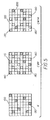
- FIG. 5 shows three halftone hypothetical halftone patterns 100, 110, 120 printed using different amounts of K ink but resulting in the same output color.
- Halftone pattern 100 is printed using only K ink, which results in sparsely spaced K ink dots 130 that will exhibit high noise when viewed by the human eye.
- Halftone pattern 110 is printed using only C, M, and Y dots 140, 150, and 160, respectively. Because each K ink dot is replaced by a triplet of CMY dots to achieve the same density, the CMY dots are spaced much closer than the K dots 130, and will be perceived as less noisy.
- Halftone pattern 120 is printed with a mixture of C, M, Y, and K ink dots 170, 180, 190, and 200, respectively, and represents the same color reproduced with an intermediate level of noise.
- the noise associated with each CMYK code value combination is used as a cost attribute to aid in the selection of a preferred CMYK code value combination to reproduce the desired output color. Techniques for measuring the perception of noise in printed images are known in the art.
- n x ,n y are the dimensions of the image region
- I(u,v) is the 2D Fourier transform of an image region I(x,y)
- CSF(u,v) is the contrast sensitivity function of the human visual system, which can be computed according to the equations described in US-A-5,822,451.
- the image region I(x,y) corresponds to the halftone patterns that result from printing a given CMYK code value combination.
- an image noise model N(C,M,Y,K) is then generated using the above equation to compute noise for a set of printed color patches substantially covering the full CMYK code value range.
- the same set of color patches may be used to develop the device model and noise model, although this is not necessarily the case.
- CMYK code value combinations may provide improved resistance to light fading (or "lightfastness") when compared to other CMYK code value combinations.
- a term may be added to the cost function to penalize CMYK code value combinations that are prone to fading, thereby discouraging their use.
- Another term that may optionally be used in the cost function is a cost attribute related to "waterfastness", or the resistance of a CMYK code value combination to smearing when wetted.
- certain CMYK code value combinations may provide for accurate color matching under a wide variety of illuminants, while others may only provide an accurate color match to the desired output color under a specific illuminant.
- CMYK code value combination This property is called the "metameric index" of the CMYK code value combination, and more robust CMYK code value combinations may be assigned a lower cost than less robust ones.
- Another term that may be used in the cost function relates to the surface gloss produced by a CMYK code value combination.
- some inkjet printers use different formulations for the K ink than are used for the CMY inks.
- the different formulations may have different gloss properties, causing an abrupt gloss change, or "differential gloss” when printing smooth gradations. These gloss changes are undesirable, and thus CMYK code value combinations prone to differential gloss may be penalized via a cost function term.
- One example of this would be to create a cost attribute in which the cost increases with the amount of black (K) ink used.
- K black
- the total cost for a CMYK code value combination is computed by summing up all of the terms in the cost function.
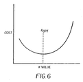
- the preferred CMYK code value combination to reproduce a desired output color is chosen as the one that minimizes the cost function, as depicted in FIG. 6.
- FIG. 6 shows (for one desired output color) the cost of each candidate CMYK code value combination plotted against the K code value.
- the preferred CMYK code value combination has a K value of K opt , which corresponds to the minimum of the cost function.
- CMYK code value combination to reproduce a desired output color
- a lattice of desired output colors spanning the range of the CIELab DICS defined by the ICC.
- L*a*b* points is defined which can then be put through the process of the present invention to determine corresponding CMYK code value combinations.
- Some of the desired output colors will lie outside of the color gamut of the printer, and therefore are not reproducible. These colors must be mapped to colors that are inside of the printers gamut using a gamut mapping algorithm.
- gamut mapping algorithms There are many other gamut mapping algorithms that are known to those skilled in the art, some of which are complex and sophisticated, and the particular form of gamut mapping is not fundamental to the invention.
- a computer program product may include one or more storage medium, for example; magnetic storage media such as magnetic disk (such as a floppy disk) or magnetic tape; optical storage media such as optical disk, optical tape, or machine readable bar code; solid-state electronic storage devices such as random access memory (RAM), or read-only memory (ROM); or any other physical device or media employed to store a computer program having instructions for controlling one or more computers to practice the method according to the present invention.
- magnetic storage media such as magnetic disk (such as a floppy disk) or magnetic tape
- optical storage media such as optical disk, optical tape, or machine readable bar code
- solid-state electronic storage devices such as random access memory (RAM), or read-only memory (ROM); or any other physical device or media employed to store a computer program having instructions for controlling one or more computers to practice the method according to the present invention.
- one of the cost attributes is a waterfastness value.
- one of the cost attributes is a lightfastness value.
- the method includes producing a set of color patches corresponding to a set of colorant control signal vectors and measuring the output color of each color patch.
- the method wherein the color transform is stored as a multidimensional look-up table indexed by a lattice of output colors.
- the method wherein the four or more colorants include cyan, magenta, yellow, and black colorants.
- the method wherein the color output device is a color printer.
Landscapes
- Engineering & Computer Science (AREA)
- Multimedia (AREA)
- Signal Processing (AREA)
- Color Image Communication Systems (AREA)
- Facsimile Image Signal Circuits (AREA)
- Color, Gradation (AREA)
- Ink Jet (AREA)
- Particle Formation And Scattering Control In Inkjet Printers (AREA)
- Image Analysis (AREA)
Abstract
Description
| C | M | Y | K | L* | a* | b* | Vol | Noise |
| 13 | 0 | 0 | 160 | 42 | -5 | 0 | 27 | 6.3 |
| 90 | 86 | 81 | 57 | 42 | -5 | 0 | 69 | 2.7 |
| 170 | 161 | 153 | 0 | 42 | -5 | 0 | 82 | 2.1 |

Claims (10)
- A method of selecting a preferred colorant control signal vector for a color output device for reproducing a desired output color, the color output device producing output colors using four or more colorants, wherein the amount of each colorant is controlled by the colorant control signal vector, comprising the steps of:a) determining a device model for the color output device relating the colorant control signal vector to the corresponding output color;b) using the device model to determine a set of valid colorant control signal vectors whose corresponding output color substantially matches the desired output color; andc) selecting the preferred colorant control signal vector from the set of valid colorant control signal vectors using a cost function responsive to one or more cost attribute(s) that vary as a function of the colorant control signal vector.
- The method of claim 1 wherein the set of valid colorant control signal vectors is limited to those satisfying a total colorant amount limit.
- The method of claim 1 wherein one of the cost attributes is a total colorant amount.
- The method of claim 1 wherein one of the cost attributes is an image noise metric.
- The method of claim 4 wherein the image noise metric is determined from an image noise model that relates the colorant control signal vector to the corresponding image noise metric.
- The method of claim 5 wherein the image noise model is formed by producing a set of color patches corresponding to a set of colorant control signal vectors and measuring the image noise metric of each color patch.
- The method of claim 1 wherein one of the cost attributes is a function of the amount of an individual colorant.
- The method of claim 7 wherein the cost attribute increases with the amount of a black colorant.
- The method of claim 1 wherein one of the cost attributes is a metameric index.
- The method of claim 1 wherein one of the cost attributes is a surface gloss value.
Applications Claiming Priority (2)
| Application Number | Priority Date | Filing Date | Title |
|---|---|---|---|
| US309866 | 2002-12-04 | ||
| US10/309,866 US7245395B2 (en) | 2002-12-04 | 2002-12-04 | Calibrating a digital printer using a cost function |
Publications (2)
| Publication Number | Publication Date |
|---|---|
| EP1447972A2 true EP1447972A2 (en) | 2004-08-18 |
| EP1447972A3 EP1447972A3 (en) | 2008-03-19 |
Family
ID=32467935
Family Applications (1)
| Application Number | Title | Priority Date | Filing Date |
|---|---|---|---|
| EP03078661A Withdrawn EP1447972A3 (en) | 2002-12-04 | 2003-11-24 | Calibrating a digital printer using a cost function |
Country Status (3)
| Country | Link |
|---|---|
| US (1) | US7245395B2 (en) |
| EP (1) | EP1447972A3 (en) |
| JP (1) | JP2004187301A (en) |
Cited By (1)
| Publication number | Priority date | Publication date | Assignee | Title |
|---|---|---|---|---|
| US8310716B2 (en) | 2007-12-05 | 2012-11-13 | Sharp Laboratories Of America, Inc. | Systems and methods for designing a set of black generation transfer curves |
Families Citing this family (21)
| Publication number | Priority date | Publication date | Assignee | Title |
|---|---|---|---|---|
| JP4475623B2 (en) * | 2002-07-31 | 2010-06-09 | キヤノン株式会社 | Color processing method and color processing apparatus |
| US7103217B2 (en) * | 2004-05-06 | 2006-09-05 | Canon Kabushiki Kaisha | Color appearance space to CMYK mapping |
| US20060072130A1 (en) * | 2004-09-28 | 2006-04-06 | Agfa Monotype Corporation | Method and system using gamut mapping templates to derive actual color gamut mapping |
| JP4583887B2 (en) * | 2004-11-11 | 2010-11-17 | 株式会社リコー | Image processing method, printer driver, image forming apparatus, image processing apparatus, and image forming system |
| US20070162480A1 (en) * | 2006-01-10 | 2007-07-12 | Kabushiki Kaisha Toshiba | System and method for monitoring consumables in a document processing environment |
| JP4855352B2 (en) * | 2007-07-03 | 2012-01-18 | 大日本スクリーン製造株式会社 | Color conversion apparatus, color conversion method, image forming system, and program |
| US7986829B2 (en) * | 2007-11-29 | 2011-07-26 | Canon Kabushiki Kaisha | Generating a transformed interim connection space for spectral data |
| US8243329B2 (en) * | 2007-12-21 | 2012-08-14 | Seiko Epson Corporation | Printing control device, print data generation device, printing system and printing control program |
| US8009325B1 (en) * | 2008-05-29 | 2011-08-30 | Adobe Systems Incorporated | Controlling black levels using a three dimensional intermediate color space |
| US8570559B2 (en) * | 2009-08-24 | 2013-10-29 | Hewlett-Packard Development Company, L.P. | Printing system and method for analyzing document properties, calculating metrics, and selecting ink set |
| US8571268B2 (en) * | 2010-03-19 | 2013-10-29 | Xerox Corporation | On-paper image quality metric using on-belt sensing |
| US8488191B2 (en) * | 2010-03-19 | 2013-07-16 | Xerox Corporation | Color mapping determination for an N-color marking device based upon image spatial noise defects |
| US8477370B2 (en) * | 2010-03-19 | 2013-07-02 | Xerox Corporation | Color mapping determination for an N-color marking device based upon color stability |
| US8531731B2 (en) * | 2010-03-19 | 2013-09-10 | Xerox Corporation | Image quality performance for a color marking device |
| US8477372B2 (en) | 2010-05-18 | 2013-07-02 | Xerox Corporation | Updating an image quality metric database to account for printer drift |
| JP5863407B2 (en) * | 2010-12-08 | 2016-02-16 | キヤノン株式会社 | Image processing apparatus, image processing method, and program |
| US8780369B2 (en) * | 2012-06-21 | 2014-07-15 | Xerox Corporation | Method and apparatus for managing common color profiles for one or more printing devices by a cloud administration system |
| CN107079076B (en) * | 2014-10-31 | 2019-11-12 | 惠普发展公司,有限责任合伙企业 | Post-process halftone images |
| EP3704668A4 (en) * | 2018-12-17 | 2021-04-07 | SZ DJI Technology Co., Ltd. | IMAGE PROCESSING METHOD AND APPARATUS |
| LU101260B1 (en) * | 2019-06-06 | 2020-12-07 | Cma Imaging Europe Sa | System and method for dosing ink in digital multichannel printers |
| US20220292319A1 (en) * | 2019-09-23 | 2022-09-15 | Hewlett-Packard Development Company, L.P. | Print agent coverage vectors |
Family Cites Families (19)
| Publication number | Priority date | Publication date | Assignee | Title |
|---|---|---|---|---|
| DE3109190C2 (en) * | 1981-03-11 | 1985-07-11 | Dr.-Ing. Rudolf Hell Gmbh, 2300 Kiel | Process for the reproduction of colored originals in four-color printing with color removal |
| US5121196A (en) * | 1988-11-18 | 1992-06-09 | Konica Corporation | Color processing method and apparatus with a color patch |
| US4930018A (en) * | 1988-12-02 | 1990-05-29 | Hewlett-Packard Company | Method and system for enhancing the quality of both color and black and white images produced by ink jet printers |
| US5012257A (en) * | 1990-03-16 | 1991-04-30 | Hewlett-Packard Company | Ink jet color graphics printing |
| US5515479A (en) * | 1992-07-23 | 1996-05-07 | Xerox Corporation | Image processing method to reduce marking material coverage in printing processes |
| US5633662A (en) * | 1992-08-05 | 1997-05-27 | Hewlett-Packard Company | Ink limiting in ink jet printing systems |
| DE69420874T2 (en) * | 1993-02-12 | 2000-05-04 | Eastman Kodak Co., Rochester | Procedure for cross-device color image calibration and improvement |
| JP3273204B2 (en) * | 1993-02-15 | 2002-04-08 | コニカ株式会社 | Color separation image processing method and apparatus for four-color printer |
| JP3360358B2 (en) * | 1993-06-30 | 2002-12-24 | 東洋インキ製造株式会社 | How to determine printing color material amount |
| US5563985A (en) * | 1994-01-05 | 1996-10-08 | Xerox Corporation | Image processing method to reduce marking material coverage in printing processes |
| US5553199A (en) * | 1994-05-03 | 1996-09-03 | Eastman Kodak Company | Method and apparatus for calibrating a four color printer |
| DE69615775T2 (en) * | 1995-09-15 | 2002-09-05 | Agfa-Gevaert N.V., Mortsel | Color separation method and device |
| US5710824A (en) * | 1996-03-13 | 1998-01-20 | Xerox Corporation | System to improve printer gamut |
| US5822451A (en) * | 1996-06-05 | 1998-10-13 | Eastman Kodak Company | Method for halftoning a multi-channel digital color image |
| US6081340A (en) * | 1997-03-31 | 2000-06-27 | Xerox Corporation | Image processing method to reduce marking material coverage with non-linear specifications |
| US6313925B1 (en) * | 1998-06-17 | 2001-11-06 | International Business Machines Corporation | System, method, and program for saving toner/ink in a color printer without sacrificing image quality |
| US6312101B1 (en) * | 1999-12-06 | 2001-11-06 | Eastman Kodak Company | Method of printing digital images using multiple colorants having substantially the same color |
| US7602525B2 (en) * | 2002-01-09 | 2009-10-13 | Seiko Epson Corporation | Method of producing color conversion table, image processing device, image processing method, program and recording medium |
| US6705703B2 (en) * | 2002-04-24 | 2004-03-16 | Hewlett-Packard Development Company, L.P. | Determination of control points for construction of first color space-to-second color space look-up table |
-
2002
- 2002-12-04 US US10/309,866 patent/US7245395B2/en not_active Expired - Fee Related
-
2003
- 2003-11-24 EP EP03078661A patent/EP1447972A3/en not_active Withdrawn
- 2003-12-03 JP JP2003405105A patent/JP2004187301A/en active Pending
Cited By (1)
| Publication number | Priority date | Publication date | Assignee | Title |
|---|---|---|---|---|
| US8310716B2 (en) | 2007-12-05 | 2012-11-13 | Sharp Laboratories Of America, Inc. | Systems and methods for designing a set of black generation transfer curves |
Also Published As
| Publication number | Publication date |
|---|---|
| JP2004187301A (en) | 2004-07-02 |
| US7245395B2 (en) | 2007-07-17 |
| US20040109178A1 (en) | 2004-06-10 |
| EP1447972A3 (en) | 2008-03-19 |
Similar Documents
| Publication | Publication Date | Title |
|---|---|---|
| US7239422B2 (en) | Color gamut mapping using a cost function | |
| US7245395B2 (en) | Calibrating a digital printer using a cost function | |
| US7365879B2 (en) | Determining sets of n-dimensional colorant control signals | |
| JP4388553B2 (en) | Generate a color conversion profile for printing | |
| US7706604B2 (en) | Production of color conversion profile for printing | |
| JP4143359B2 (en) | Method for calculating the amount of pigment and method for correcting the input image | |
| US5710827A (en) | Halftone dither cell with integrated preferred color matching | |
| EP0665674A2 (en) | Colour printer system | |
| US7433513B2 (en) | Scaling an array of luminace values | |
| US7190485B2 (en) | Method for multilevel printing of digital images using reduced colorant amounts | |
| EP1437678B1 (en) | Colorimetric ink depletion processing for printers | |
| US8218206B2 (en) | Color conversion using transformed gamuts | |
| EP0949807B1 (en) | Transforms for digital images | |
| EP1195984A2 (en) | Image processing apparatus, print control apparatus, method of image processing, and recording medium | |
| JP4380503B2 (en) | Lookup table creation method and separation method | |
| US20070070366A1 (en) | Fast color interpolation | |
| US7583407B2 (en) | Color processing method and apparatus | |
| JP3968949B2 (en) | Printing control apparatus, printing apparatus, printing control method, printing method, recording medium, and image processing apparatus | |
| EP0665678A2 (en) | Colour printer system | |
| US8705115B1 (en) | Generation of inverse transfer function for image rendering device | |
| Samadzadegan et al. | Spatio-spectral gamut mapping and separation | |
| JP2004299171A (en) | Separation processing into a plurality of ink components including chromatic primary color ink and chromatic secondary color ink | |
| JP2012099937A (en) | Image processing apparatus and method therefor |
Legal Events
| Date | Code | Title | Description |
|---|---|---|---|
| PUAI | Public reference made under article 153(3) epc to a published international application that has entered the european phase |
Free format text: ORIGINAL CODE: 0009012 |
|
| AK | Designated contracting states |
Kind code of ref document: A2 Designated state(s): AT BE BG CH CY CZ DE DK EE ES FI FR GB GR HU IE IT LI LU MC NL PT RO SE SI SK TR |
|
| AX | Request for extension of the european patent |
Extension state: AL LT LV MK |
|
| PUAL | Search report despatched |
Free format text: ORIGINAL CODE: 0009013 |
|
| AK | Designated contracting states |
Kind code of ref document: A3 Designated state(s): AT BE BG CH CY CZ DE DK EE ES FI FR GB GR HU IE IT LI LU MC NL PT RO SE SI SK TR |
|
| AX | Request for extension of the european patent |
Extension state: AL LT LV MK |
|
| 17P | Request for examination filed |
Effective date: 20080808 |
|
| AKX | Designation fees paid |
Designated state(s): DE GB |
|
| 17Q | First examination report despatched |
Effective date: 20081217 |
|
| STAA | Information on the status of an ep patent application or granted ep patent |
Free format text: STATUS: THE APPLICATION IS DEEMED TO BE WITHDRAWN |
|
| 18D | Application deemed to be withdrawn |
Effective date: 20090428 |