EP1447936A1 - Data communication unit and method thereof for iterative decoding - Google Patents
Data communication unit and method thereof for iterative decoding Download PDFInfo
- Publication number
- EP1447936A1 EP1447936A1 EP03290328A EP03290328A EP1447936A1 EP 1447936 A1 EP1447936 A1 EP 1447936A1 EP 03290328 A EP03290328 A EP 03290328A EP 03290328 A EP03290328 A EP 03290328A EP 1447936 A1 EP1447936 A1 EP 1447936A1
- Authority
- EP
- European Patent Office
- Prior art keywords
- receiving
- iterative decoding
- data blocks
- communication unit
- data
- Prior art date
- Legal status (The legal status is an assumption and is not a legal conclusion. Google has not performed a legal analysis and makes no representation as to the accuracy of the status listed.)
- Withdrawn
Links
Images


Classifications
-
- H—ELECTRICITY
- H04—ELECTRIC COMMUNICATION TECHNIQUE
- H04L—TRANSMISSION OF DIGITAL INFORMATION, e.g. TELEGRAPHIC COMMUNICATION
- H04L1/00—Arrangements for detecting or preventing errors in the information received
- H04L1/12—Arrangements for detecting or preventing errors in the information received by using return channel
- H04L1/16—Arrangements for detecting or preventing errors in the information received by using return channel in which the return channel carries supervisory signals, e.g. repetition request signals
- H04L1/18—Automatic repetition systems, e.g. Van Duuren systems
- H04L1/1812—Hybrid protocols; Hybrid automatic repeat request [HARQ]
-
- H—ELECTRICITY
- H03—ELECTRONIC CIRCUITRY
- H03M—CODING; DECODING; CODE CONVERSION IN GENERAL
- H03M13/00—Coding, decoding or code conversion, for error detection or error correction; Coding theory basic assumptions; Coding bounds; Error probability evaluation methods; Channel models; Simulation or testing of codes
-
- H—ELECTRICITY
- H04—ELECTRIC COMMUNICATION TECHNIQUE
- H04L—TRANSMISSION OF DIGITAL INFORMATION, e.g. TELEGRAPHIC COMMUNICATION
- H04L1/00—Arrangements for detecting or preventing errors in the information received
- H04L1/004—Arrangements for detecting or preventing errors in the information received by using forward error control
- H04L1/0045—Arrangements at the receiver end
- H04L1/0047—Decoding adapted to other signal detection operation
- H04L1/005—Iterative decoding, including iteration between signal detection and decoding operation
- H04L1/0051—Stopping criteria
-
- H—ELECTRICITY
- H04—ELECTRIC COMMUNICATION TECHNIQUE
- H04L—TRANSMISSION OF DIGITAL INFORMATION, e.g. TELEGRAPHIC COMMUNICATION
- H04L1/00—Arrangements for detecting or preventing errors in the information received
- H04L1/12—Arrangements for detecting or preventing errors in the information received by using return channel
- H04L1/16—Arrangements for detecting or preventing errors in the information received by using return channel in which the return channel carries supervisory signals, e.g. repetition request signals
- H04L1/1607—Details of the supervisory signal
- H04L1/1628—List acknowledgements, i.e. the acknowledgement message consisting of a list of identifiers, e.g. of sequence numbers
-
- H—ELECTRICITY
- H04—ELECTRIC COMMUNICATION TECHNIQUE
- H04L—TRANSMISSION OF DIGITAL INFORMATION, e.g. TELEGRAPHIC COMMUNICATION
- H04L1/00—Arrangements for detecting or preventing errors in the information received
- H04L1/08—Arrangements for detecting or preventing errors in the information received by repeating transmission, e.g. Verdan system
-
- H—ELECTRICITY
- H04—ELECTRIC COMMUNICATION TECHNIQUE
- H04L—TRANSMISSION OF DIGITAL INFORMATION, e.g. TELEGRAPHIC COMMUNICATION
- H04L1/00—Arrangements for detecting or preventing errors in the information received
- H04L1/12—Arrangements for detecting or preventing errors in the information received by using return channel
- H04L1/16—Arrangements for detecting or preventing errors in the information received by using return channel in which the return channel carries supervisory signals, e.g. repetition request signals
- H04L1/18—Automatic repetition systems, e.g. Van Duuren systems
- H04L1/1829—Arrangements specially adapted for the receiver end
Definitions
- This invention relates to decoding of data in communication units, and particularly to communication units supporting packet data transmissions.
- the invention is applicable to, but not limited to, speeding up an iterative decoding algorithm of compound codes.
- these services can be divided into two groups, real-time and non-real-time.
- the real-time services typically require a low average data packet delay, arranged such that they can cope with a certain error rate.
- the non-real-time services typically require some limitation against delay, but often need a very low error rate.
- Real-time services have been traditionally used only with Forward Error Correction (FEC) mechanisms that guarantee a bounded delay but deliver data with an error rate depending on channel conditions (which in wireless channels is highly variable).
- FEC Forward Error Correction
- these services can only operate up to a maximum error rate. When this error-rate value is exceeded, even with a low delay, the service is not delivered.
- the decoder is unable to correctly decode the received codeword, irrespective of the number of iterations employed. In such situations, the decoder wastes time and power on continuing with the iterative decoding process is a vain and ultimately fruitless attempt to decode the codeword, i.e. the packet to be decoded by the receiver, until a decision is finally made that the codeword must be retransmitted.
- SNR signal to noise ratio
- a first known correction mechanism for correcting received data packets corrupted during transmission, uses only forward error correction (FEC) coding.
- FEC forward error correction
- an FEC mechanism guarantees a low delay and low delay variation, it cannot guarantee a low error rate.
- a second known correction mechanism uses re-transmission of erroneous data packets, as illustrated in FIG. 1.
- the re-transmission process is achieved via a feedback channel from the receiver to the transmitter, which is used to indicate whether the data packet has been correctly received or not.
- This correction mechanism is termed Automatic Repeat reQuest (ARQ) and is widely used in wired communication systems since it provides an error rate as low as needed.
- ARQ Automatic Repeat reQuest
- the ARQ re-transmission process commences by receiving digital information, in step 105. Iterative decoding is then applied to the received information in step 110.
- the iterative decoding process is applied a number (k) times, until the decoding operation converges to yield recovered data. If, after k times, the codeword has not been accurately decoded, in step 115, the process requests a re-transmission of the information, in step 120.
- ARQ When ARQ is used over a wireless channel, which typically encounters a much higher data packet error rate, an ARQ mechanism often leads to very poor transmission performance. For instance, this poor performance results from, say, the same data packet requiring a large number of re-transmissions to be successfully received. To mitigate this effect, ARQ is usually used with a limited maximum number of re-transmissions, which bounds the delay but does not guarantee the error rate.
- H-ARQ Hybrid ARQ
- IR incremental redundancy
- the UE 200 comprises, for example, standard radio frequency (RF) components and circuits, such as an antenna 202 preferably coupled to an antenna switch 204 for receiving a digitally modulated RF signal.
- RF radio frequency
- the antenna switch 204 provides isolation between a receiver and a transmitter chain within the UE 200.
- the receiver chain typically includes receiver front-end circuitry 206 (effectively providing reception, filtering and intermediate or baseband frequency conversion).
- the front-end circuitry 206 is serially coupled to a signal processing function 208 to convert, inter-alia, the received digitised signal into blocks of data for subsequent processing.
- An output from the signal processing function is provided to a suitable output device 210, such as a speaker.
- the signal processor function 208 which may be a baseband (back-end) signal processing receiver integrated circuit in other embodiments, has been adapted to incorporate the inventive concepts described below.
- the signal processing function 208 in the context of the present invention, will perform numerous signal processing tasks, such as: symbol timing recovery, demodulation, decoding, burst building, de-multiplexing, de-interleaving, re-ordering, etc.
- the decoding function in the signal processing function 208 has been adapted to include a prior decision function as to whether the iterative decoding operation will likely converge. If it is determined that the subsequent iterative decoding operation will likely converge, the decoding operation is performed. However, and advantageously, if it is determined that the subsequent iterative decoding operation will be unlikely to converge, the iterative decoding operation is not performed and a re-transmission of the data blocks requested.
- the signal processing function 208 has been adapted to perform, or be replaced in software hardware or firmware by, an iterative decoder function as described further below with reference to FIG. 3.
- the receiver chain also includes received signal strength indicator (RSSI) circuitry 212 coupled to the receiver front-end circuitry 206 and the signal processing function 208 (generally realised by a digital signal processor (DSP)).
- a controller 214 also coupled to the receiver front-end circuitry 206 and the signal processing function 208, may therefore receive bit error rate (BER) or frame error rate (FER) data from recovered information.
- the controller 214 is coupled to the memory device 216 for storing operating regimes, such as decoding/encoding functions and the like.
- a timer 218 is typically coupled to the controller 214 to control the timing of operations (transmission or reception of time-dependent signals) within the UE 200. In the context of the present invention, the timer 218 dictates the timing of speech signals, in the transmit (encoding) path and/or the receive (decoding) path.
- the transmit chain essentially includes an input device, such as a microphone transducer coupled in series via transmit signal processor 228 to a transmitter/ modulation circuit 222. Thereafter, any transmit signal is passed through a power amplifier 224 to be radiated from the antenna 202.
- the transmitter/ modulation circuitry 222 and the power amplifier 224 are operationally responsive to the controller, with an output from the power amplifier coupled to the duplex filter or circulator 204.
- the transmitter/ modulation circuitry 222 and receiver front-end circuitry 206 comprise frequency up-conversion and frequency down-conversion functions (not shown).
- the various adapted components within a UE 200 can be realised in discrete or integrated component form. More generally, the functionality associated with deciding whether to decode or not may be implemented in a respective communication unit in any suitable manner. For example, new apparatus may be added to a conventional Node-B or UE, or alternatively existing parts of a conventional communication unit may be adapted, for example by reprogramming one or more processors therein. As such, the required adaptation, for example the incorporation of a decision function to determine the likelihood of convergence of the iterative decoding process, may be implemented in the form of processor-implementable instructions stored on a storage medium, such as a floppy disk, hard disk, PROM, RAM or any combination of these or other storage media.
- a storage medium such as a floppy disk, hard disk, PROM, RAM or any combination of these or other storage media.
- a front-end receiver 206 receives a digital information signal and routes it to a demodulator 302.
- a determination is made, in decision function 304, as to whether it is likely that the iterative decoding operation will converge.
- the proposed technique prevents running the iterative decoder 310 when the test detects a-priori that the iterative decoder 310 cannot decode the demodulated information correctly.
- the iterative decoding function 310 comprises, for instance, Peral's Belief Propagation (BP) algorithm.
- BP Peral's Belief Propagation
- SISO soft-input soft-output
- the SISO decoders 312, 314 are separated by a de-leaving function 322 and an interleaving function 324 to reformulate and formulate the data stream for the decoding operation. Interleaving is used to avoid burst errors having an independent identically distributed (IID) error statistic, which makes it easier for the data stream to be treated.
- the de-interleaving function is the reverse process, aiming to restore the sequence in the original order.
- the ARQ re-transmission process commences by receiving information, in step 405.
- an iterative decoding 'convergence likelihood' test is performed, as shown in step 410.
- the details of the preferred 'convergence likelihood' test are further described in relation to FIG. 5 and FIG. 6. If the determination of the convergence likelihood test yields that iterative decoding will be unlikely to converge, in step 410, an immediate request for re-transmission is sent to the transmitting unit, as shown in step 430.
- step 410 iterative decoding is then applied to the received information in step 415.
- the iterative decoding is applied a number (k) times, until the decoding converges, as shown in step 420. If, after k times, the codeword has not been accurately decoded, in step 425, the process requests a re-transmission of the information, in step 430.
- the determination as to whether a decoding operation of a received information signal will converge is based on an analysis of the Density Evolution (DE) of the demodulated data.
- DE Density Evolution
- a graphical representation 500 of this is shown in FIG. 5, where bit-nodes 510 represent the bits of the codeword and the check-nodes 520 represent the parity check equations that the bit-nodes are related to.
- the illustrated graphical representation of Density Evolution uses a regular LDPC Code (3,6), where each bit-node 510 is connected to three check-nodes 520 and each check-node 520 is connected to six bit-nodes 510.
- the messages applied to a DE function are distributed usually in a manner similar to a Gaussian response.
- a Gaussian approximation it is possible to propagate a one-dimensional parameter through the graph, i.e. describing the density instead the density of the messages itself.
- this parameter can be the mean of the density or the mutual information.
- the term 'message' identifies the parameter selected for propagation through the graph, for example mutual information or a mean of the probability density distribution of the original LLR message.
- DE is used as a method to evaluate the performance of the real BP decoder.
- a bit-node 'i' 610 will be connected to a check-node k, if this bit-node participates in the k th parity check equation.
- the real BP decoder operates in the following manner.
- an initial message 605 is associated to each bit-node 510, related to the output of the channel.
- Each bit-node 510 sends the initial message (in a log-likelihood ratio (LLR) form), identified as v_k, to all the corresponding check-nodes that the bit-node 510 is connected to, where k is the index identifying the respective bit-node 510.
- LLR log-likelihood ratio
- v_sk is the message coming from the k th bit-node.
- each check-node 520 collects all transmitted messages, except from bit-node 'i' 610, which was used to compute c_i 620 and is returned to the i th bit-node 610.
- This DE process is repeated, i.e. it follows the same iterative process but instead of the (LLR) messages being propagated, the densities of the messages propagate through the graph.
- the bit-nodes compute the message to be sent to the check-node as follows.
- c_pk is the message coming from the k th check-nodes and c_0 is the initial message coming form the channel (the channel output). This procedure is done in parallel for all the bit-nodes and the check-nodes.
- the preferred embodiment of the present invention utilises Density Evolution (DE), as DE obtains a track of the densities of messages exchanged between nodes as they propagate through the graph.
- DE Density Evolution
- the inventors of the present invention have found that DE provides a good estimate of the convergence likelihood of the decoding process.
- using a DE enables a good estimate to be obtained, as the finite length code is cyclic in its graph, whereas the corresponding infinite length code is cycle free.
- inventive concepts described herein can be applied to any mechanism that provides a-priori information about the convergence of the decoder, and is not limited to the use of Density Evolution.
- an embodiment of the present invention consists of adding a derivation of the Density Evolution prior to decoding the received information. This derivation triggers the real iterative decoding when it converges. Alternatively, if the derivation guarantees that there will be no convergence of the Density Evolution, i.e. the codeword will not be correctly decoded, and then the iterative decoding operation is not performed until a re-transmission of the data block(s) is received.
- the information message is encoded using Turbo Codes or LDPC with length 'n' and split into 'M' bursts, as shown in step 705.
- the transmitter starts sending a first burst/ initial message.
- the decoder receives the i th burst, in step 710, and determines whether the DE has already converged, as shown in step 715. If the DE has not already converged, in step 715, a determination is made as to whether it is likely that the DE will subsequently converge, as shown in step 720.
- step 720 the process immediately requests a re-transmission of the burst, as shown in step 725.
- a re-transmission is requested as the non-convergence of the DE attests that the iterative decoding will not converge.
- the additional burst will contain more redundancy.
- step 720 the process commences iterative decoding, in step 730, because the DE convergence shows that iterative decoding is likely to converge too.
- the iterative decoding operation occurs 'k' times, as shown in step 735.
- the process delivers the codeword to the user, as shown in step 740.
- the decoder stores the received burst and asks, via a negative acknowledgment, for a re-transmission of the burst with more redundancy, as shown in step 725.
- step 715 focuses on DE convergence, which provides only an indicator of the convergence likelihood of the real decoder, in step 730.
- DE convergence shows that the real iterative decoder has a chance to converge.
- Non-convergence of the DE indicates that there is no chance of the real decoder converging.
- subsequent transmissions include additional redundancy, thereby increasing the convergence likelihood.
- BP C_BP*m
- BP is the total complexity of the iterative decoding technique (i.e. Belief Propagation).
- DE is a useful mechanism to evaluate the performance of infinite length codes, as it provides information about the convergence of a finite-length BP decoder. This is confirmed in the paper titled "The Capacity of Low-Density Parity-Check Codes Under Message Passing Decoding” authored by T.J. Richardson and R. L Urbanke. In the paper titled “On the Construction of Some Capacity-Approaching Coding Scheme", authored by S.Y Chung in a PhD Thesis, MIT, September 2000, a description of the DE convergence performance for small BER is described.
- the inventors of the present invention have recognised an opportunity to use such a DE convergence performance, in improving an operation of iterative decoders.
- DE converges to a fixed point less then '1' (i.e. the decoder has insufficient information from which to decode the infinite length code)
- the finite length decoder will yield small BER. Therefore, the receiver does not even try to run the BP decoder, and asks for new redundancy (i.e. additional error correction applied to the previously sent data).
- 'm' is the number of bursts necessary to have Belief Propagation (i.e. real decoding) convergence.
- M_nc is the number of bursts necessary to have DE converged.
- PI complexity of the present invention
- BP known technique
- N* ⁇ _i defines the number of bit-nodes connected to 'i' edges in the graph
- 'N' is the number of bit-nodes
- dv (dc) is the maximum degree of variable node (check-node).
- the number of different variable nodes (check-nodes) ddv (ddc) is bounded by dv (dc).
- irregular LDPC has the following values: ddv ⁇ 10-15 and ddc ⁇ 2-3.
- the inventors of the present invention have identified that the gain provided by the method is approximately 15% in terms of running time. This evaluation is based on simulation time on the same computer, with and without the method and is directly linked with the gain in terms of number of operations.
- inventive concepts can be applied in any modem (wireless or wired) that includes an iterative decoder.
- 3G (and beyond 3 rd generation (B3G) including 4G) communication units using turbo codes and iterative decoders may utilize the inventive concepts described herein.
- inventive concepts hereinafter described are equally applicable to other wireless communication systems, for example, GPRS (Generalized Packet Radio Service), or Edge, or 802.11x family of systems.
- GPRS Generalized Packet Radio Service
- Edge or 802.11x family of systems.
Abstract
A method (400) for receiving one or more data blocks in a
data communication system comprises the step of receiving
one or more data blocks at a receiving communication
unit. The method further comprises the steps of
determining (410) a-priori whether an iterative decoding
operation of the one or more received data blocks is
likely to converge; and requesting (420), by said
receiving unit in response to determining that an
iterative decoding operation is unlikely to converge, a
re-transmission of said one or more data blocks. A
communication unit and a communication system are also
provided.
In this manner, the method prevents a receiver from
performing wasteful (in a processing power and/or time
sense) iterative decoding operations. Moreover, the
overall delay in the receiver is also improved.
Description
- This invention relates to decoding of data in communication units, and particularly to communication units supporting packet data transmissions. The invention is applicable to, but not limited to, speeding up an iterative decoding algorithm of compound codes.
- Third generation wireless systems, presently being designed for implementation in the near future, have as a requirement the support of speech and data. Different types of data services will be available with different Quality of Service (QoS) requirements, particularly in terms of error rate and delay.
- Typically, these services can be divided into two groups, real-time and non-real-time. The real-time services typically require a low average data packet delay, arranged such that they can cope with a certain error rate. On the other hand, the non-real-time services typically require some limitation against delay, but often need a very low error rate.
- Real-time services have been traditionally used only with Forward Error Correction (FEC) mechanisms that guarantee a bounded delay but deliver data with an error rate depending on channel conditions (which in wireless channels is highly variable). However, these services can only operate up to a maximum error rate. When this error-rate value is exceeded, even with a low delay, the service is not delivered.
- In the field of this invention, it is known to use various data correction mechanisms to minimise the error rate. In particular, for wireless communication systems, convolutional codes are well known and are widely used. Recently, a novel class of FEC data packet (data block) transmissions, referred to as compound codes, such as 'turbo-codes' and 'Low Density Parity Check' (LDPC) codes, have appeared. These codes offer very good protection for an acceptable complexity and outperform all classical coding schemes. One of the key features of compound codes, that enable the codes to achieve a remarkable performance, is the use of iterative decoding. Iterative decoding is where the received information is processed several times by the same decoder, with the exchange of soft information performed between successive iterations. After each iteration, the coding performance improves until the decoding process converges to a correctly received and decoded data stream.
- However, clearly when the signal to noise ratio (SNR) of the received data is too low, the decoder is unable to correctly decode the received codeword, irrespective of the number of iterations employed. In such situations, the decoder wastes time and power on continuing with the iterative decoding process is a vain and ultimately fruitless attempt to decode the codeword, i.e. the packet to be decoded by the receiver, until a decision is finally made that the codeword must be retransmitted.
- A first known correction mechanism, for correcting received data packets corrupted during transmission, uses only forward error correction (FEC) coding. However, although an FEC mechanism guarantees a low delay and low delay variation, it cannot guarantee a low error rate.
- A second known correction mechanism uses re-transmission of erroneous data packets, as illustrated in FIG. 1. The re-transmission process is achieved via a feedback channel from the receiver to the transmitter, which is used to indicate whether the data packet has been correctly received or not. This correction mechanism is termed Automatic Repeat reQuest (ARQ) and is widely used in wired communication systems since it provides an error rate as low as needed.
- As shown in FIG. 1, the ARQ re-transmission process commences by receiving digital information, in
step 105. Iterative decoding is then applied to the received information instep 110. The iterative decoding process, as the name suggests, is applied a number (k) times, until the decoding operation converges to yield recovered data. If, after k times, the codeword has not been accurately decoded, instep 115, the process requests a re-transmission of the information, instep 120. - When ARQ is used over a wireless channel, which typically encounters a much higher data packet error rate, an ARQ mechanism often leads to very poor transmission performance. For instance, this poor performance results from, say, the same data packet requiring a large number of re-transmissions to be successfully received. To mitigate this effect, ARQ is usually used with a limited maximum number of re-transmissions, which bounds the delay but does not guarantee the error rate.
- FEC used alone does not guarantee the delivered packet error rate, whereas ARQ with an unlimited number of re-transmissions does not provide a bounded delay. As a result, FEC and ARQ are often used jointly. This is commonly referred to as Hybrid ARQ (H-ARQ). H-ARQ is known as an efficient mechanism to provide error-free or low error rate transmissions in a wireless system, where the information flow is segmented into data packets.
- A further known mechanism whose performance is determined by a re-transmission methodology is incremental redundancy (IR). In IR schemes, the first transmission is made using a very high coding rate, i.e. little error correction information is transmitted. Hence, as is often the case, the first reception is likely to be unsuccessful. Subsequently, additional error correction information is transmitted and combined with the previous information in order to increase the probability of successful decoding.
- It is known that all linear codes can be represented in a graphical context, with iterative coding such as Turbo codes and LDPC predominantly being represented in this manner. A graphical representation helps to model the iterative decoding process by highlighting the evolution of the soft information between the nodes of the graph. However, graphical representation of codes is more suitable for infinite length codes, where the codes are analytically tractable if some approximations are made.
- A need therefore exists for an improved decoding mechanism, which reduces a complexity in the iterative decoding process, for example when the decoding operation using Turbo codes or LDPC and can be represented graphically.
- In accordance with the present invention, there is provided a method for receiving one or more data blocks, a data communication system and a data communication unit, as defined in the appended Claims.
-
- FIG. 1 illustrates a flowchart of a classical re-transmission decoding process.
- Exemplary embodiments of the present invention will now be described, with reference to the accompanying drawings, in which:
- FIG. 2 illustrates a wireless digital communication unit adapted in accordance with a preferred embodiment of the present invention;
- FIG. 3 illustrates a block diagram of an iterative decoder adapted in accordance with a preferred embodiment of the present invention;
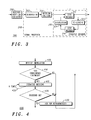
- FIG. 4 illustrates a flowchart of the proposed re-transmission process for a generic decoder, adapted according to the preferred embodiment of the present invention;
- FIG. 5 illustrates a graphical representation of a Density Evolution process utilised in the preferred embodiment of the present invention;
- FIG. 6 illustrates a further graphical representation of a Density Evolution process utilised in the preferred embodiment of the present invention; and
- FIG. 7 illustrates a flowchart of the proposed re-transmission process when applied to an incremental redundancy decoder, according to the preferred embodiment of the present invention.
-
- Referring now to FIG. 2, there is shown a block diagram of a wireless digital communication unit, for example a third generation cellular subscriber unit, hereinafter referred to as user equipment (UE) 200, which is adapted to support the inventive concepts of the preferred embodiments of the present invention. As known in the art, and replicated here for completeness, the UE 200 comprises, for example, standard radio frequency (RF) components and circuits, such as an
antenna 202 preferably coupled to anantenna switch 204 for receiving a digitally modulated RF signal. Theantenna switch 204 provides isolation between a receiver and a transmitter chain within theUE 200. The receiver chain typically includes receiver front-end circuitry 206 (effectively providing reception, filtering and intermediate or baseband frequency conversion). The front-end circuitry 206 is serially coupled to asignal processing function 208 to convert, inter-alia, the received digitised signal into blocks of data for subsequent processing. An output from the signal processing function is provided to asuitable output device 210, such as a speaker. - In accordance with the preferred embodiment of the invention, the
signal processor function 208, which may be a baseband (back-end) signal processing receiver integrated circuit in other embodiments, has been adapted to incorporate the inventive concepts described below. In practice, thesignal processing function 208, in the context of the present invention, will perform numerous signal processing tasks, such as: symbol timing recovery, demodulation, decoding, burst building, de-multiplexing, de-interleaving, re-ordering, etc. - In particular, the decoding function in the
signal processing function 208 has been adapted to include a prior decision function as to whether the iterative decoding operation will likely converge. If it is determined that the subsequent iterative decoding operation will likely converge, the decoding operation is performed. However, and advantageously, if it is determined that the subsequent iterative decoding operation will be unlikely to converge, the iterative decoding operation is not performed and a re-transmission of the data blocks requested. Preferably, thesignal processing function 208 has been adapted to perform, or be replaced in software hardware or firmware by, an iterative decoder function as described further below with reference to FIG. 3. - For completeness, the receiver chain also includes received signal strength indicator (RSSI)
circuitry 212 coupled to the receiver front-end circuitry 206 and the signal processing function 208 (generally realised by a digital signal processor (DSP)). Acontroller 214, also coupled to the receiver front-end circuitry 206 and thesignal processing function 208, may therefore receive bit error rate (BER) or frame error rate (FER) data from recovered information. Thecontroller 214 is coupled to thememory device 216 for storing operating regimes, such as decoding/encoding functions and the like. Atimer 218 is typically coupled to thecontroller 214 to control the timing of operations (transmission or reception of time-dependent signals) within theUE 200. In the context of the present invention, thetimer 218 dictates the timing of speech signals, in the transmit (encoding) path and/or the receive (decoding) path. - As regards the transmit chain, as also known in the art, this essentially includes an input device, such as a microphone transducer coupled in series via transmit
signal processor 228 to a transmitter/modulation circuit 222. Thereafter, any transmit signal is passed through apower amplifier 224 to be radiated from theantenna 202. The transmitter/modulation circuitry 222 and thepower amplifier 224 are operationally responsive to the controller, with an output from the power amplifier coupled to the duplex filter orcirculator 204. The transmitter/modulation circuitry 222 and receiver front-end circuitry 206 comprise frequency up-conversion and frequency down-conversion functions (not shown). - The various adapted components within a UE 200 (or other iterative decoding communication unit) can be realised in discrete or integrated component form. More generally, the functionality associated with deciding whether to decode or not may be implemented in a respective communication unit in any suitable manner. For example, new apparatus may be added to a conventional Node-B or UE, or alternatively existing parts of a conventional communication unit may be adapted, for example by reprogramming one or more processors therein. As such, the required adaptation, for example the incorporation of a decision function to determine the likelihood of convergence of the iterative decoding process, may be implemented in the form of processor-implementable instructions stored on a storage medium, such as a floppy disk, hard disk, PROM, RAM or any combination of these or other storage media.
- Referring now to FIG. 3, a preferred embodiment of the present invention is described. A front-
end receiver 206 receives a digital information signal and routes it to ademodulator 302. In accordance with the preferred embodiment of the present invention, after demodulation of the received digital information signal, a determination is made, indecision function 304, as to whether it is likely that the iterative decoding operation will converge. Advantageously, the proposed technique prevents running theiterative decoder 310 when the test detects a-priori that theiterative decoder 310 cannot decode the demodulated information correctly. - If, based on the demodulated information, it is deemed likely that the iterative decoding function 10 is performed. In this embodiment of the present invention, the
iterative decoding function 310 comprises, for instance, Peral's Belief Propagation (BP) algorithm. This is the basis of soft-input soft-output (SISO)decoders SISO decoders interleaving function 324 to reformulate and formulate the data stream for the decoding operation. Interleaving is used to avoid burst errors having an independent identically distributed (IID) error statistic, which makes it easier for the data stream to be treated. The de-interleaving function is the reverse process, aiming to restore the sequence in the original order. - The preferred process is illustrated in the
flowchart 400 FIG. 4. The ARQ re-transmission process commences by receiving information, instep 405. Notably, in accordance with the preferred embodiment of the present invention, an iterative decoding 'convergence likelihood' test is performed, as shown instep 410. The details of the preferred 'convergence likelihood' test are further described in relation to FIG. 5 and FIG. 6. If the determination of the convergence likelihood test yields that iterative decoding will be unlikely to converge, instep 410, an immediate request for re-transmission is sent to the transmitting unit, as shown instep 430. - However, if the determination of the convergence likelihood yields that iterative decoding will likely converge, in
step 410, iterative decoding is then applied to the received information instep 415. The iterative decoding, as the name suggests, is applied a number (k) times, until the decoding converges, as shown instep 420. If, after k times, the codeword has not been accurately decoded, instep 425, the process requests a re-transmission of the information, instep 430. - In accordance with the preferred embodiment of the present invention, the determination as to whether a decoding operation of a received information signal will converge is based on an analysis of the Density Evolution (DE) of the demodulated data. A
graphical representation 500 of this is shown in FIG. 5, where bit-nodes 510 represent the bits of the codeword and the check-nodes 520 represent the parity check equations that the bit-nodes are related to. The illustrated graphical representation of Density Evolution uses a regular LDPC Code (3,6), where each bit-node 510 is connected to three check-nodes 520 and each check-node 520 is connected to six bit-nodes 510. - The messages applied to a DE function are distributed usually in a manner similar to a Gaussian response. Thus, by applying a Gaussian approximation, it is possible to propagate a one-dimensional parameter through the graph, i.e. describing the density instead the density of the messages itself. It is known that this parameter can be the mean of the density or the mutual information. In the following description of DE, the term 'message' identifies the parameter selected for propagation through the graph, for example mutual information or a mean of the probability density distribution of the original LLR message.
- Referring now to FIG. 6, an example of the
DE process 600 is illustrated graphically, where a message (c_0) 605 is received from the demodulator. In this context, DE is used as a method to evaluate the performance of the real BP decoder. A bit-node 'i' 610 will be connected to a check-node k, if this bit-node participates in the kth parity check equation. - The real BP decoder operates in the following manner. Upon a first iteration, an
initial message 605 is associated to each bit-node 510, related to the output of the channel. Each bit-node 510 (with one bit-node shown for clarity purposes only) sends the initial message (in a log-likelihood ratio (LLR) form), identified as v_k, to all the corresponding check-nodes that the bit-node 510 is connected to, where k is the index identifying the respective bit-node 510. After processing the initial message, each check-node returns a message to the respective bit-nodes that it is connected to. - Suppose that the set of bit-nodes connected to this check-node is S={s1, s2, ... .sdc}. It is necessary to compute the message that the check-node sends to the ith bit-node (where 'i' ∈ (1, ...dc)). Here, the message c_i will be a function of the incoming message from all the bit-nodes except from the message sent by the bit-node 'i', that is:
- Where v_sk is the message coming from the kth bit-node.
- In this regard, each check-
node 520 collects all transmitted messages, except from bit-node 'i' 610, which was used to compute c_i 620 and is returned to the ith bit-node 610. - This DE process is repeated, i.e. it follows the same iterative process but instead of the (LLR) messages being propagated, the densities of the messages propagate through the graph. At the next iteration, the bit-nodes compute the message to be sent to the check-node as follows. Suppose that the set of check-nodes connected to that bit-node is defined by P={p1, p2, ... .pdv}, it is necessary to compute the message that that bit-node sends to the 1th check-node (where '1' ∈ (1, ...dv)). The message v_1 is given by the sum of all the incoming messages, except from the message coming from the 1th check-node, that is:
- Where c_pk is the message coming from the kth check-nodes and c_0 is the initial message coming form the channel (the channel output). This procedure is done in parallel for all the bit-nodes and the check-nodes.
- The preferred embodiment of the present invention utilises Density Evolution (DE), as DE obtains a track of the densities of messages exchanged between nodes as they propagate through the graph. It is known that DE provides exact results for an infinite length of the code. However, in the case of finite length codes, the inventors of the present invention have found that DE provides a good estimate of the convergence likelihood of the decoding process. Notably, using a DE enables a good estimate to be obtained, as the finite length code is cyclic in its graph, whereas the corresponding infinite length code is cycle free.
- As a result, when it is determined that the DE will not converge for a corresponding infinite length code, it is guaranteed that the real iterative decoder will not converge for a finite length code.
- It is envisaged that the inventive concepts described herein can be applied to any mechanism that provides a-priori information about the convergence of the decoder, and is not limited to the use of Density Evolution.
- Thus, in summary, an embodiment of the present invention consists of adding a derivation of the Density Evolution prior to decoding the received information. This derivation triggers the real iterative decoding when it converges. Alternatively, if the derivation guarantees that there will be no convergence of the Density Evolution, i.e. the codeword will not be correctly decoded, and then the iterative decoding operation is not performed until a re-transmission of the data block(s) is received.
- In order to quantify the improvements proposed, let us consider applying the inventive concepts in an HARQ Incremental Redundancy scheme, as described with regard to the
flowchart 700 of FIG. 7. The information message is encoded using Turbo Codes or LDPC with length 'n' and split into 'M' bursts, as shown instep 705. As described, the transmitter starts sending a first burst/ initial message. The decoder receives the ith burst, instep 710, and determines whether the DE has already converged, as shown instep 715. If the DE has not already converged, instep 715, a determination is made as to whether it is likely that the DE will subsequently converge, as shown instep 720. If it is determined that the DE is unlikely to converge, instep 720, the process immediately requests a re-transmission of the burst, as shown instep 725. A re-transmission is requested as the non-convergence of the DE attests that the iterative decoding will not converge. In an Incremental Redundancy system, the additional burst will contain more redundancy. - If it is determined that the DE is likely to converge, in
step 720, the process commences iterative decoding, instep 730, because the DE convergence shows that iterative decoding is likely to converge too. The iterative decoding operation occurs 'k' times, as shown instep 735. - If the process is able to decode the complete codeword, the process delivers the codeword to the user, as shown in
step 740. However, if the decoder is unable to decode the complete codeword, the decoder stores the received burst and asks, via a negative acknowledgment, for a re-transmission of the burst with more redundancy, as shown instep 725. - It should be noted that in this case (i.e. DE convergence but non-convergence of the iterative decoder), it is not necessary to test the DE convergence any more (i.e. test for the considered codeword). Thus, when the additional burst is received,
step 715 directly moves to step 735. Therefore,step 715 focuses on DE convergence, which provides only an indicator of the convergence likelihood of the real decoder, instep 730. DE convergence shows that the real iterative decoder has a chance to converge. Non-convergence of the DE indicates that there is no chance of the real decoder converging. Moreover, once the DE has converged, it is not necessary to do this test again, as subsequent transmissions include additional redundancy, thereby increasing the convergence likelihood. - Obviously, it is interesting to a receiver designer to evaluate any additional cost consequence of applying the additional step of a DE-based convergence likelihood test. Therefore, an example scenario is described below and the performance cost compared with the processing cost of performing the iterative decoder operation, irrespective of whether or not it is determined whether the decoder operation will converge.
- If the complexity of BP decoder is defined as 'C_BP', it means that after the reception of 'm' bursts:
- Where BP is the total complexity of the iterative decoding technique (i.e. Belief Propagation).
- As described above, DE is a useful mechanism to evaluate the performance of infinite length codes, as it provides information about the convergence of a finite-length BP decoder. This is confirmed in the paper titled "The Capacity of Low-Density Parity-Check Codes Under Message Passing Decoding" authored by T.J. Richardson and R. L Urbanke. In the paper titled "On the Construction of Some Capacity-Approaching Coding Scheme", authored by S.Y Chung in a PhD Thesis, MIT, September 2000, a description of the DE convergence performance for small BER is described.
- Notably, the inventors of the present invention have recognised an opportunity to use such a DE convergence performance, in improving an operation of iterative decoders. Thus, when DE converges to a fixed point less then '1' (i.e. the decoder has insufficient information from which to decode the infinite length code), there is little hope that the finite length decoder will yield small BER. Therefore, the receiver does not even try to run the BP decoder, and asks for new redundancy (i.e. additional error correction applied to the previously sent data).
- Let us assume the same channel characteristic as before, where there is correct decoding after m bursts, the following definition applies:
- Where 'm' is the number of bursts necessary to have Belief Propagation (i.e. real decoding) convergence. M_nc is the number of bursts necessary to have DE converged. If we define the complexity of the Density Evolution computation as 'C_DE', the computation utilizing the proposed inventive concepts yields:
- It is noteworthy that, once the DE has converged, it will necessarily converge when new bursts arrive. As a result, once it has converged, it is not necessary to compute it again.
- It can be shown that the complexity of the present invention (PI) is significantly less than the known technique (BP). Hence, PI<<BP demonstrates the advantages in terms of speed and complexity achieved by the proposed algorithm.
- Let us therefore define an approximation of the complexity, in terms of the number of multiplication operations. Two cases can then be compared: a first case where a Density Evolution test is applied prior to a real iterative decoder, as described in the present invention; and a second case using an iterative decoding algorithm on its own.
- The graph that represents the code may be defined by both the bit-node degree sequence distribution λ = (λ_1, λ_2 ... λ_dv) and the parity check-nodes degree distribution ρ = (ρ_1, ... . .,ρ_dc). Here, N*λ_i defines the number of bit-nodes connected to 'i' edges in the graph, 'N' is the number of bit-nodes, and dv (dc) is the maximum degree of variable node (check-node). Thus, the number of different variable nodes (check-nodes) ddv (ddc) is bounded by dv (dc).
- The complexity of the DE approach is proportional to the product of 'dc' and 'dv' for a single iteration, i.e.:
- Where 'n_DE' is the number of iterations needed to detect whether Density Evolution converges or not. Defining 'n_Demax' as the maximum allowed number of iterations, the calculation yields:
- It is known that, in general, irregular LDPC has the following values: ddv ≅ 10-15 and ddc ≅ 2-3.
- In the case of the Iterative Decoding the complexity can be computed in terms of number of multiplications, exponential and logarithm computations. Since we can say that exponential or logarithm operations are more complex than multiplications, it is easy to show that:
- Where 'n_edges' is the number of edges in the graphs (in general this is a very high number when considering that a normal LDPC's length is N=5000 to 10000) and 'n_BP' is the number of iterations necessary for the iterative decoding algorithm to decide if the frame will converge or not.
- Also, in that case, a maximum number of iterations 'n_Bpmax' yield:
- If we now define:
- And
- Since, 4·dc·dv « 9·n_edges, it is clear that the additional complexity associated with introducing a convergence likelihood test of the present invention is minimal compared to the processing time and power savings of avoiding performing an iterative decoding operation.
- In practice, using an optimised Belief Propagation algorithm, even with the inclusion of an optional iterative decoding process based on Cross Entropy for turbo decoding, the inventors of the present invention have identified that the gain provided by the method is approximately 15% in terms of running time. This evaluation is based on simulation time on the same computer, with and without the method and is directly linked with the gain in terms of number of operations.
- Although the preferred embodiment of the present invention is described with reference to a BP algorithm based on Cross Entropy, it is envisaged that other methods may be used, for example methods based on CRC for example as described by R.Y. Shao, S. Lin, M.P.C Fossorier, in the paper titled "Two simple stopping criteria".
- It will be understood by a skilled artisan that the inventive concepts can be applied in any modem (wireless or wired) that includes an iterative decoder. For example, it is envisaged that 3G (and beyond 3rd generation (B3G) including 4G) communication units, using turbo codes and iterative decoders may utilize the inventive concepts described herein. It is also within the contemplation of the invention that the inventive concepts hereinafter described are equally applicable to other wireless communication systems, for example, GPRS (Generalized Packet Radio Service), or Edge, or 802.11x family of systems.
In conclusion, it will be understood that the above described inventive concepts, or at least embodiments thereof, tend to provide the following advantages, singly or in combination: - (i) It prevents a receiver from performing wasteful (in a processing power and/or time sense) iterative decoding operations.
- (ii) The overall delay in a receiver iteratively decoding received data is reduced.
- (iii) The prior DE test may also provide a rough approximation of the frame error rate (FER) prior to performing a real decoding operation.
-
- Whilst the specific and preferred implementations of the embodiments of the present invention are described above, it is clear that one skilled in the art could readily apply variations and modifications of such inventive concepts.
- Thus, a method of decoding one or more data blocks, a communication unit and a communication system, have been described, whereby the disadvantages associated with known prior art arrangements have been substantially alleviated.
Claims (14)
- A method (400, 700) for receiving one or more data blocks in a data communication system, the method comprising the step of:receiving one or more data blocks at a receiving communication unit;
the method characterised by the steps of:determining (410) a-priori whether an iterative decoding operation of said one or more received data blocks is likely to converge; andrequesting (420), by said receiving unit in response to determining that an iterative decoding operation is unlikely to converge, a re-transmission (430) of said one or more data blocks. - The method (400, 700) for receiving one or more data blocks according to Claim 1, wherein in response to a determination by said receiving unit that an iterative decoding operation is likely to converge, performing an iterative decoding operation (415).
- The method (400, 700) for receiving one or more data blocks according to Claim 2, wherein said step of performing an iterative decoding operation (415) is dependent upon said iterative decoding operation being capable of graphical representation.
- The method (400, 700) for receiving one or more data blocks according to any preceding Claim, wherein said step of determining comprises performing a density evolution analysis on said received data block.
- The method (400, 700) for receiving one or more data blocks according to any preceding Claim, wherein the iterative decoding scheme is a hybrid automatic repeat request (ARQ) scheme.
- The method (400, 700) for receiving one or more data blocks according to any preceding Claim, wherein the iterative decoding scheme uses an incremental redundancy scheme.
- The method (400, 700) for receiving one or more data blocks according to any preceding Claim, wherein the iterative decoding scheme comprises turbo decoding or low density parity check.
- The method (400, 700) for receiving one or more data blocks according to any preceding Claim, wherein the data communication system is a 3GPP or UMTS communication system.
- A communications system adapted to support the method of any of the preceding Claims.
- A communications unit (300) adapted to support the method of any of preceding Claims 1 to 8.
- A storage medium storing processor-implementable instructions for controlling a processor to carry out the method of any of Claims 1 to 8.
- A communication unit (300) for receiving one or more data packets in a data communication system, the communication unit (300) comprising:a receiver receiving one or more data blocks;
the communication unit (300) characterised by:a signal processor (308), operably coupled to said receiver, configured to determine (410) a-priori whether an iterative decoding operation to be performed on said one or more data blocks is likely to converge, and, in response to determining that an iterative decoding operation is unlikely to converge, requests a re-transmission of said one or more data blocks. - The communication unit (300) according to Claim 12, wherein said communication unit (300) employs a hybrid automatic repeat request scheme.
- The communication unit (300) according to Claim 12 or 13, wherein said communication unit (300) is a Node-B or a UE configured for operation on a UMTS or 3GPP wireless communication system.
Priority Applications (1)
| Application Number | Priority Date | Filing Date | Title |
|---|---|---|---|
| EP03290328A EP1447936A1 (en) | 2003-02-11 | 2003-02-11 | Data communication unit and method thereof for iterative decoding |
Applications Claiming Priority (1)
| Application Number | Priority Date | Filing Date | Title |
|---|---|---|---|
| EP03290328A EP1447936A1 (en) | 2003-02-11 | 2003-02-11 | Data communication unit and method thereof for iterative decoding |
Publications (1)
| Publication Number | Publication Date |
|---|---|
| EP1447936A1 true EP1447936A1 (en) | 2004-08-18 |
Family
ID=32669034
Family Applications (1)
| Application Number | Title | Priority Date | Filing Date |
|---|---|---|---|
| EP03290328A Withdrawn EP1447936A1 (en) | 2003-02-11 | 2003-02-11 | Data communication unit and method thereof for iterative decoding |
Country Status (1)
| Country | Link |
|---|---|
| EP (1) | EP1447936A1 (en) |
Cited By (2)
| Publication number | Priority date | Publication date | Assignee | Title |
|---|---|---|---|---|
| US7917830B2 (en) | 2007-09-28 | 2011-03-29 | Via Technologies, Inc. | Turbo decoder and iteration stopping method thereof |
| US9479240B1 (en) | 2014-01-31 | 2016-10-25 | Quantenna Communications, Inc. | Composite beamforming to coordinate concurrent WLAN links |
Citations (4)
| Publication number | Priority date | Publication date | Assignee | Title |
|---|---|---|---|---|
| WO2001037433A1 (en) * | 1999-11-17 | 2001-05-25 | Motorola Inc. | Adaptive hybrid arq using turbo code structure |
| US20010004761A1 (en) * | 1997-05-30 | 2001-06-21 | Ephraim Zehavi | Method and apparatus for providing error protection for over the air file transfer |
| WO2001063869A1 (en) * | 2000-02-25 | 2001-08-30 | Nokia Corporation | Adaptive method and arrangement for implementing incremental redundancy in reception |
| EP1193881A2 (en) * | 2000-09-29 | 2002-04-03 | Sony Corporation | Automatic retransmission ARQ for turbo-coded data |
-
2003
- 2003-02-11 EP EP03290328A patent/EP1447936A1/en not_active Withdrawn
Patent Citations (4)
| Publication number | Priority date | Publication date | Assignee | Title |
|---|---|---|---|---|
| US20010004761A1 (en) * | 1997-05-30 | 2001-06-21 | Ephraim Zehavi | Method and apparatus for providing error protection for over the air file transfer |
| WO2001037433A1 (en) * | 1999-11-17 | 2001-05-25 | Motorola Inc. | Adaptive hybrid arq using turbo code structure |
| WO2001063869A1 (en) * | 2000-02-25 | 2001-08-30 | Nokia Corporation | Adaptive method and arrangement for implementing incremental redundancy in reception |
| EP1193881A2 (en) * | 2000-09-29 | 2002-04-03 | Sony Corporation | Automatic retransmission ARQ for turbo-coded data |
Non-Patent Citations (1)
| Title |
|---|
| RICHARDSON T J ET AL: "The capacity of low-density parity-check codes under message-passing decoding", IEEE TRANSACTIONS ON INFORMATION THEORY, IEEE INC. NEW YORK, US, vol. 47, no. 2, February 2001 (2001-02-01), pages 599 - 618, XP002228426, ISSN: 0018-9448 * |
Cited By (2)
| Publication number | Priority date | Publication date | Assignee | Title |
|---|---|---|---|---|
| US7917830B2 (en) | 2007-09-28 | 2011-03-29 | Via Technologies, Inc. | Turbo decoder and iteration stopping method thereof |
| US9479240B1 (en) | 2014-01-31 | 2016-10-25 | Quantenna Communications, Inc. | Composite beamforming to coordinate concurrent WLAN links |
Similar Documents
| Publication | Publication Date | Title |
|---|---|---|
| JP4143603B2 (en) | Method for generating high-speed H-ARQ response using stop rule for turbo decoding | |
| US7600172B2 (en) | Method and device for decoding packets of data within a hybrid ARQ scheme | |
| US7992073B2 (en) | Decoding device, decoding method, and receiving apparatus | |
| Chen et al. | A survey and tutorial on low-complexity turbo coding techniques and a holistic hybrid ARQ design example | |
| EP1193881B1 (en) | Automatic retransmission ARQ for turbo-coded data | |
| EP1482643A2 (en) | Method and apparatus for decoding a low density parity check (LDPC) code in a communication system | |
| JP2013518488A (en) | Reduction of error floor in iteratively decoded FEC code | |
| US10153864B2 (en) | Method for dynamic and selective FD-DSDF transmission of a digital signal for a MAMRC system with several full-duplex relays, and corresponding program product and relay device | |
| WO2007099468A1 (en) | Method and apparatus for transmitting and receiving a data block in a wireless communication system | |
| US20030145269A1 (en) | Methods and apparatus of signal demodulation combining with different modulations and coding for wireless communications | |
| JP3440092B1 (en) | Error correction decoding device and error correction decoding method | |
| US20050022101A1 (en) | Fast iteration termination of Turbo decoding | |
| US10122496B2 (en) | Method for dynamic and selective FD-DSDF transmission of a digital signal for a MARC system with a full-duplex relay, and corresponding program product and relay device | |
| US7272771B2 (en) | Noise and quality detector for use with turbo coded signals | |
| Zaitsev et al. | Structural adaptation of the turbo code coder and decoder for generating the transmission repeat request under conditions of uncertainty | |
| EP1447936A1 (en) | Data communication unit and method thereof for iterative decoding | |
| Huang et al. | Digital fountain codes system model and performance over AWGN and Rayleigh fading channels | |
| US20080024335A1 (en) | Local Erasure Map Decoder | |
| US20100318876A1 (en) | Decoding device, decoding method, decoding program, reception device, and communication system | |
| Breddermann | On rate-compatible insertion convolutional turbo codes and HARQ for mobile communications | |
| Riediger et al. | Application of Reed-Solomon codes with erasure decoding to type-II hybrid ARQ transmission | |
| EP1381181A1 (en) | Communication system and method with hybrid ARQ packet combining | |
| CN113366872A (en) | LPWAN communication protocol design using parallel concatenated convolutional codes | |
| Lo et al. | A Design of Two-Stage Hybrid ARQ Scheme using LDPC Codes | |
| JP2017158015A (en) | Communication system, control method for communication system, transmission device and reception device |
Legal Events
| Date | Code | Title | Description |
|---|---|---|---|
| PUAI | Public reference made under article 153(3) epc to a published international application that has entered the european phase |
Free format text: ORIGINAL CODE: 0009012 |
|
| AK | Designated contracting states |
Kind code of ref document: A1 Designated state(s): AT BE BG CH CY CZ DE DK EE ES FI FR GB GR HU IE IT LI LU MC NL PT SE SI SK TR |
|
| AX | Request for extension of the european patent |
Extension state: AL LT LV MK RO |
|
| AKX | Designation fees paid | ||
| REG | Reference to a national code |
Ref country code: DE Ref legal event code: 8566 |
|
| STAA | Information on the status of an ep patent application or granted ep patent |
Free format text: STATUS: THE APPLICATION IS DEEMED TO BE WITHDRAWN |
|
| 18D | Application deemed to be withdrawn |
Effective date: 20050219 |
|
| P01 | Opt-out of the competence of the unified patent court (upc) registered |
Effective date: 20230520 |