EP1447872A1 - Electronic apparatus and method of controlling operation of the same - Google Patents
Electronic apparatus and method of controlling operation of the same Download PDFInfo
- Publication number
- EP1447872A1 EP1447872A1 EP04000520A EP04000520A EP1447872A1 EP 1447872 A1 EP1447872 A1 EP 1447872A1 EP 04000520 A EP04000520 A EP 04000520A EP 04000520 A EP04000520 A EP 04000520A EP 1447872 A1 EP1447872 A1 EP 1447872A1
- Authority
- EP
- European Patent Office
- Prior art keywords
- electronic apparatus
- tilt
- fuel cell
- warning
- cell unit
- Prior art date
- Legal status (The legal status is an assumption and is not a legal conclusion. Google has not performed a legal analysis and makes no representation as to the accuracy of the status listed.)
- Granted
Links
Images


Classifications
-
- H—ELECTRICITY
- H01—ELECTRIC ELEMENTS
- H01M—PROCESSES OR MEANS, e.g. BATTERIES, FOR THE DIRECT CONVERSION OF CHEMICAL ENERGY INTO ELECTRICAL ENERGY
- H01M8/00—Fuel cells; Manufacture thereof
- H01M8/10—Fuel cells with solid electrolytes
- H01M8/1009—Fuel cells with solid electrolytes with one of the reactants being liquid, solid or liquid-charged
-
- H—ELECTRICITY
- H01—ELECTRIC ELEMENTS
- H01M—PROCESSES OR MEANS, e.g. BATTERIES, FOR THE DIRECT CONVERSION OF CHEMICAL ENERGY INTO ELECTRICAL ENERGY
- H01M16/00—Structural combinations of different types of electrochemical generators
- H01M16/003—Structural combinations of different types of electrochemical generators of fuel cells with other electrochemical devices, e.g. capacitors, electrolysers
- H01M16/006—Structural combinations of different types of electrochemical generators of fuel cells with other electrochemical devices, e.g. capacitors, electrolysers of fuel cells with rechargeable batteries
-
- H—ELECTRICITY
- H01—ELECTRIC ELEMENTS
- H01M—PROCESSES OR MEANS, e.g. BATTERIES, FOR THE DIRECT CONVERSION OF CHEMICAL ENERGY INTO ELECTRICAL ENERGY
- H01M8/00—Fuel cells; Manufacture thereof
- H01M8/04—Auxiliary arrangements, e.g. for control of pressure or for circulation of fluids
- H01M8/04082—Arrangements for control of reactant parameters, e.g. pressure or concentration
- H01M8/04186—Arrangements for control of reactant parameters, e.g. pressure or concentration of liquid-charged or electrolyte-charged reactants
-
- H—ELECTRICITY
- H01—ELECTRIC ELEMENTS
- H01M—PROCESSES OR MEANS, e.g. BATTERIES, FOR THE DIRECT CONVERSION OF CHEMICAL ENERGY INTO ELECTRICAL ENERGY
- H01M8/00—Fuel cells; Manufacture thereof
- H01M8/04—Auxiliary arrangements, e.g. for control of pressure or for circulation of fluids
- H01M8/04298—Processes for controlling fuel cells or fuel cell systems
- H01M8/04313—Processes for controlling fuel cells or fuel cell systems characterised by the detection or assessment of variables; characterised by the detection or assessment of failure or abnormal function
-
- H—ELECTRICITY
- H01—ELECTRIC ELEMENTS
- H01M—PROCESSES OR MEANS, e.g. BATTERIES, FOR THE DIRECT CONVERSION OF CHEMICAL ENERGY INTO ELECTRICAL ENERGY
- H01M2250/00—Fuel cells for particular applications; Specific features of fuel cell system
- H01M2250/30—Fuel cells in portable systems, e.g. mobile phone, laptop
-
- H—ELECTRICITY
- H01—ELECTRIC ELEMENTS
- H01M—PROCESSES OR MEANS, e.g. BATTERIES, FOR THE DIRECT CONVERSION OF CHEMICAL ENERGY INTO ELECTRICAL ENERGY
- H01M8/00—Fuel cells; Manufacture thereof
- H01M8/10—Fuel cells with solid electrolytes
- H01M8/1009—Fuel cells with solid electrolytes with one of the reactants being liquid, solid or liquid-charged
- H01M8/1011—Direct alcohol fuel cells [DAFC], e.g. direct methanol fuel cells [DMFC]
-
- Y—GENERAL TAGGING OF NEW TECHNOLOGICAL DEVELOPMENTS; GENERAL TAGGING OF CROSS-SECTIONAL TECHNOLOGIES SPANNING OVER SEVERAL SECTIONS OF THE IPC; TECHNICAL SUBJECTS COVERED BY FORMER USPC CROSS-REFERENCE ART COLLECTIONS [XRACs] AND DIGESTS
- Y02—TECHNOLOGIES OR APPLICATIONS FOR MITIGATION OR ADAPTATION AGAINST CLIMATE CHANGE
- Y02B—CLIMATE CHANGE MITIGATION TECHNOLOGIES RELATED TO BUILDINGS, e.g. HOUSING, HOUSE APPLIANCES OR RELATED END-USER APPLICATIONS
- Y02B90/00—Enabling technologies or technologies with a potential or indirect contribution to GHG emissions mitigation
- Y02B90/10—Applications of fuel cells in buildings
-
- Y—GENERAL TAGGING OF NEW TECHNOLOGICAL DEVELOPMENTS; GENERAL TAGGING OF CROSS-SECTIONAL TECHNOLOGIES SPANNING OVER SEVERAL SECTIONS OF THE IPC; TECHNICAL SUBJECTS COVERED BY FORMER USPC CROSS-REFERENCE ART COLLECTIONS [XRACs] AND DIGESTS
- Y02—TECHNOLOGIES OR APPLICATIONS FOR MITIGATION OR ADAPTATION AGAINST CLIMATE CHANGE
- Y02E—REDUCTION OF GREENHOUSE GAS [GHG] EMISSIONS, RELATED TO ENERGY GENERATION, TRANSMISSION OR DISTRIBUTION
- Y02E60/00—Enabling technologies; Technologies with a potential or indirect contribution to GHG emissions mitigation
- Y02E60/10—Energy storage using batteries
-
- Y—GENERAL TAGGING OF NEW TECHNOLOGICAL DEVELOPMENTS; GENERAL TAGGING OF CROSS-SECTIONAL TECHNOLOGIES SPANNING OVER SEVERAL SECTIONS OF THE IPC; TECHNICAL SUBJECTS COVERED BY FORMER USPC CROSS-REFERENCE ART COLLECTIONS [XRACs] AND DIGESTS
- Y02—TECHNOLOGIES OR APPLICATIONS FOR MITIGATION OR ADAPTATION AGAINST CLIMATE CHANGE
- Y02E—REDUCTION OF GREENHOUSE GAS [GHG] EMISSIONS, RELATED TO ENERGY GENERATION, TRANSMISSION OR DISTRIBUTION
- Y02E60/00—Enabling technologies; Technologies with a potential or indirect contribution to GHG emissions mitigation
- Y02E60/30—Hydrogen technology
- Y02E60/50—Fuel cells
-
- Y—GENERAL TAGGING OF NEW TECHNOLOGICAL DEVELOPMENTS; GENERAL TAGGING OF CROSS-SECTIONAL TECHNOLOGIES SPANNING OVER SEVERAL SECTIONS OF THE IPC; TECHNICAL SUBJECTS COVERED BY FORMER USPC CROSS-REFERENCE ART COLLECTIONS [XRACs] AND DIGESTS
- Y02—TECHNOLOGIES OR APPLICATIONS FOR MITIGATION OR ADAPTATION AGAINST CLIMATE CHANGE
- Y02P—CLIMATE CHANGE MITIGATION TECHNOLOGIES IN THE PRODUCTION OR PROCESSING OF GOODS
- Y02P90/00—Enabling technologies with a potential contribution to greenhouse gas [GHG] emissions mitigation
- Y02P90/40—Fuel cell technologies in production processes
Definitions
- the present invention relates to a technique of controlling an operation of an electronic apparatus operable using, for example, a direct methanol fuel cell as a power supply.
- DMFC direct methanol fuel cell
- the DMFC generates electric energy by chemical reaction between oxygen and methanol provided as fuel.
- the DMFC has a structure in which an electrolyte is interposed between two electrodes made of porous metal or carbon. Since the DMFC produces no hazardous wastes, its practicality is strongly desired.
- Jpn. Pat. Appln. KOKAI Publication No. 2002-063920 discloses a technique of preventing drawbacks from occurring when a fuel cell unit tilts. According to this technique, in order to prevent water from flowing backward to a fuel cell from a water tank even when the unit tilts, tubes are connected between outlets of the fuel cell and inlets of the water tank with their sleeves tucked up.
- a tilt sensor should sense a tilt of the fuel cell unit.
- Embodiments of the present invention may provide an electronic apparatus capable of preventing a danger due to a tilt of a cell unit and a method of controlling an operation of the electronic apparatus.
- an electronic apparatus comprising a body; a fuel cell capable of generating power by chemical reaction and supplying the power to the body; a sensor to sense a tilt of the fuel cell; and a notifying portion to notify a user of information of the tilt sensed by the sensor.
- a method of controlling an operation of an electronic apparatus operable using a fuel cell capable of generating power by chemical reaction comprising sensing a tilt of the fuel cell; and notifying a user of information of the tilt.
- FIG. 1 is an external view of an electronic apparatus system according to an embodiment of the present invention.
- the electronic apparatus system includes an electronic apparatus 1 and a fuel cell unit 2 that is detachable from the electronic apparatus 1.
- the electronic apparatus 1 is a notebook personal computer in which a top cover having an LCD (liquid crystal device) on its inner side is attached to the main body by a hinge mechanism such that it can freely be opened and closed.
- the electronic apparatus 1 is capable of being operated by power supplied from the fuel cell unit 2.
- the fuel cell unit 2 includes a DMFC capable of generating power by chemical reaction and a repeatedly chargeable/dischargeable secondary battery.
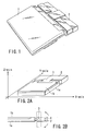
- FIGS. 2A and 2B are perspective and side views illustrating a variable mechanism capable of varying the angle of the fuel cell unit 2 to the electronic apparatus 1.
- the electronic apparatus 1 includes a main body 1a and a liquid crystal panel 1b and is connected to the fuel cell unit 2 through a variable mechanism 3.
- the fuel cell unit 2 is attached to the variable mechanism 3 by a hinge section such that it can be rotated in the Z-axis direction (vertical direction) in FIG. 2A with respect to the main body 1a.
- the angle of the fuel cell unit 2 to the main body 1a can vertically be varied 90 degrees at the maximum.
- the unit 2 is fastened on the variable mechanism 3 by a fastening member to such an extent that a user can easily rotate the unit 2 by his or her hand. If the user rotates the fuel cell unit 2 and moves his or her hand off the unit 2, a fixed angle is maintained between the unit 2 and mechanism 3 by moderate friction and fastening force.
- the fuel cell unit 2 contains a tilt sensor 4 for sensing the angle and direction of the tilted fuel cell unit.
- the fuel cell unit 2 has to be put in a horizontal position for safety.
- the tilt sensor 4 notifies the main body 1a whether the fuel cell unit 2 is safe or dangerous.
- an angle between the main body 1a and fuel cell unit 2 can be varied as described above. As shown in FIGS. 3A and 3B, therefore, the main body 1a can be put in a state (not horizontal) where a user can easily operate the electronic apparatus 1 while keeping the unit 2 in a horizontal position. This state is effective in, for example, using the electronic apparatus system on user's lap in an automobile.
- an angle between the main body 1a and fuel cell unit 2 can be set at 90 degrees.
- the electronic apparatus system can safely be carried with the main body 1a in a vertical position. It is thus possible to save a user from stopping the DMFC while the system moves.
- FIG. 4 is a schematic block diagram of the fuel cell unit 2.
- the fuel cell unit 2 includes a microcomputer 21, a DMFC 22, a secondary battery 23, a charging circuit 24, a supply control circuit 25 and an operating button 26.
- the microcomputer 21 controls the entire operation of the fuel cell unit 2 and has a communication function of transmitting/receiving signals to/from the electronic apparatus 1.
- the microcomputer 21 controls the operations of the DMFC 22 and secondary battery 23 in response to an indicating signal and performs a process corresponding to the depression of the operating button 26.
- the microcomputer 21 notifies the main body of the electronic apparatus 1 of information indicating a tilt angle and a tilt direction of the fuel cell and displays the information on the liquid crystal panel 1b of the electronic apparatus 1.
- the DMFC 22 includes a detachable cartridge fuel tank 221 and outputs power that is generated by chemical reaction between air (oxygen) and methanol stored in the fuel tank 221.
- the chemical reaction occurs in a reaction section referred to as a cell stack or the like.
- the DMFC 22 has an auxiliary mechanism such as a pump.
- the DMFC also has a mechanism to notify the microcomputer 21 of whether the fuel tank 221 is attached or detached, the amount of methanol remaining in the fuel tank 221, the operating status of the auxiliary mechanism, and the current amount of output power.
- the tilt sensor 4 is attached to the DMFC 22.
- the tilt sensor 4 can be provided except where the DMFC 22 is located within the fuel cell unit 2.
- the secondary battery 23 stores power output from the DMFC 22 through the charging circuit 24 and outputs the power in response to the indication from the microcomputer 21.
- the secondary battery 23 has an EEPROM 231 that holds basic information indicative of discharge characteristics and the like.
- the EEPROM 231 can be accessed from the microcomputer 21.
- the secondary battery 23 has a mechanism to notify the microcomputer 21 of both the current output voltage and current output current.
- the microcomputer 21 computes the amount of power remaining in the secondary battery 23 based on both the basic information read out of the EEPROM 231 and the output voltage and current indicated by the secondary battery 23. Assume here that the secondary battery 23 is a lithium battery (LIB).
- LIB lithium battery
- the charging circuit 24 charges the secondary battery 23 with power output from the DMFC 22.
- the microcomputer 21 controls whether the secondary battery 23 is charged or not.
- the supply control circuit 25 outputs the power of the DMFC 22 and secondary battery 23 to the outside according to the circumstances.
- the operating button 26 is a button to start/stop and control the tilt sensor 4.
- FIG. 5 is a schematic block diagram of the electronic apparatus 1.
- the electronic apparatus 1 includes a CPU 11, a RAM (main memory) 12, an HDD 13, a display controller 14, a keyboard controller 15 and a power supply controller 16. These are connected to a system bus.
- the CPU 11 controls the entire operation of the electronic apparatus 1 and executes various programs stored in the RAM 12.
- the RAM 12 is a memory device serving as a main memory of the electronic apparatus 1 to store various programs to be executed by the CPU 11 and various types of data to be used for the programs.
- the HDD 13 is a memory device serving as an external memory of the electronic apparatus 1 to store various programs and a large amount of data as an auxiliary device of the RAM 12.
- the display controller 14 controls the output side of a user interface in the electronic apparatus 1 and displays image data created by the CPU 11 on an LCD 141.
- the keyboard controller 15 controls the input side of the user interface in the electronic apparatus 1.
- the controller 15 converts the operations of a keyboard 151 and a pointing device 152 into numbers and supplies them to the CPU 11 via a register included therein.
- the power supply controller 16 controls the supply of power to the respective components of the electronic apparatus 1.
- the controller 16 has a power-receiving function of receiving power from the fuel cell unit 2 and a communication function of transmitting/receiving signals to/from the fuel cell unit 2. It is the microcomputer 21 in the fuel cell unit 2 shown in FIG. 4 that transmits/receives signals to/from the power supply controller 16.
- the electronic apparatus 1 By communication between the microcomputer 21 in the fuel cell unit 2 and the power supply controller 16 in the electronic apparatus 1, the electronic apparatus 1 is notified of the information indicating a tilt angle and a tilt direction of the DMFC 22 (or fuel cell unit 2) included in the fuel cell unit 2. Thus, the electronic apparatus 1 controls an operation based on the information.
- the CPU 11 is able to acquire information indicating the tilt angle and tilt direction of the DMFC 22 (or the fuel cell unit 2) from the fuel cell unit 2 and display the information on the screen of the LCD 141.
- the CPU 11 also executes control programs to issue and stop a given warning, stop and restart the operation of the DMFC 22, and stop the operation of the electronic apparatus 1 in accordance with variations in the tilt angle acquired from the fuel cell unit 2.
- FIG. 6 is a chart showing various conditions selected in accordance with sensed tilt angles.
- one of "danger area X,” “warning area Y” and “safety area Z” is selected according to the tilt angle sensed by the tilt sensor 4.
- the "danger area X" indicates that the tilt angle is so wide that the electronic apparatus is in a dangerous condition.
- the electronic apparatus 1 stores necessary data and shuts down the OS.
- the DMFC 22 thus stops operating at once.
- the "warning area Y" is located between the “danger area X" and “safety area Z" and indicates that the electronic apparatus 1 is not a safe condition.
- the tilt angle corresponds to the "warning area Y”
- a user is warned that the fuel cell unit 2 should be reset to a horizontal condition.
- the "safety area Z" indicates that the electronic apparatus 1 is in a safe condition since no tilt angle is formed or the tilt angle is smaller.
- the electronic apparatus 1 is continuously used in a normal condition as it is.
- FIGS. 7A and 7B are charts each showing an example of display of information of tilt angle and tilt direction displayed on the screen of the LCD 141 of the electronic apparatus 1.
- FIGS. 7A and 7B show tilt conditions in X- and Y-axis directions (see FIG. 2A). These tilt conditions are displayed at once on the screen of the LCD 141. The tilt conditions in both the X- and Y-axis directions are graphically displayed as shown in FIG. 6. The actual tilts of the DMFC 22 are displayed on the graphically displayed tilt conditions.
- the tilt in the X-axis direction corresponds to the "safety area Z.”
- the tilt in the Y-axis direction corresponds to the "warning area Y.” Since the current tilts and directions are graphically displayed, a user can easily understand what condition the DMFC 22 lies in.
- the RAM 12 holds in advance a first threshold value indicating a tilt angle of the border between the "safety area Z" and “warning area Y” and a second threshold value indicating a tilt angle of the border between the "warning area Y" and “danger area X " as threshold information used for controlling the operation.
- the CPU 11 compares the threshold information with information of the actual tilt angle obtained from the fuel cell unit 2 to recognize which of the areas corresponds to each of the tilt angles in the X- and Y-axis directions.
- the CPU 11 monitors the tilt of the DMFC 22 (or fuel cell unit 2) (step S1) and determines which of the "danger area X,” “warning area Y” and "safety area Z" corresponds to the angle of the tilt (step S2).
- step S3 When the tilt angle corresponds to the "safety area Z,” the operation is continued as it is (step S3) and the process is repeated from step S1.
- a message “Put fuel cell unit back to horizontal position” is displayed on the screen of the LCD 141 to give a warning to the user (step S4).
- the warning can be accompanied with a beep.
- step S7 When the tilt angle corresponds to the "danger area X,” necessary data is stored and the OS is shut down to stop the operation of the DMFC 22 immediately (step S7).
- step S5 the CPU 11 determines whether the tilt angle varies (step S5).
- step S6 the warning is stopped (step S6) and the process is repeated from step S1.
- step S4 the tilt angle corresponds to "danger area X" after the warning, necessary data is stored and the OS is shut down to stop the operation of the DMFC 22 immediately (step S7).
- step S8 the CPU 11 determines whether the operation can be continued by the power of the secondary battery (step S8) .
- step S13 If the operation cannot be continued, the electronic apparatus 1 also stops operation (step S13).
- step S9 the warning is given again to the user (step S9) and the CPU 11 determines whether the tilt angle varies (step S10).
- step S11 the warning is stopped (step S11) and the DMFC 22 is started up again (step S12).
- step S1 the tilt angle corresponds to "warning area Y" after the warning
- step S9 the electronic apparatus 1 stops operation (step S13).
- a process of giving a warning to the user by display and sound, a process of stopping the operation of the DMFC 22, a process of stopping the operation of the electronic apparatus 1, etc. are safely performed according to which of "danger area X,” “warning area Y” and “safety area Z" corresponds to the tilt angle sensed by the tilt sensor 4. Therefore, the user can safely use the electronic apparatus system mounted with the DMFC.
- the microcomputer 21 senses it.
- the microcomputer 21 sends the electronic apparatus 1 with a signal indicating the abnormality
- the CPU 11 stores necessary data and shuts down the OS to stop the operation of the DMFC 22 and that of the electronic apparatus 1.
- the microcomputer 21 senses it.
- the microcomputer 21 sends the electronic apparatus 1 with a signal indicating the abnormality
- the CPU 11 gives a warning to a user displaying, e.g., a message "Fuel cell unit cannot be used due to abnormality in tilt sensor. Receive support.” on the screen of the LCD 141.
- the CPU 11 determines whether or not the electronic apparatus 1 is driven by an AC adapter (step T1). If it is not driven by the AC adapter (if it is driven by the DMFC 22), the CPU 11 gives an instruction to drive the electronic apparatus 1 by the AC adapter to a user through the screen of the LCD 141 (step T2).
- the CPU 11 After the CPU 11 confirms that the electronic apparatus 1 is driven by the AC adapter, it gives the user an instruction to tilt the fuel cell unit 2 in an arbitrary direction through the screen of the LCD 141 (step T3).
- the screen of the LCD 141 displays the current tilt angle (step T4).
- the user checks whether the tilt sensor 4 operates normally on the screen of the LCD 141. In other words, the user confirms whether the direction and tilt angle at which the fuel cell unit 2 is tilted coincide with the direction and tilt angle displayed on the screen (step T5). It is desirable to display, e.g., a message "Receive support if no coincidence occurs in direction and tilt angle.” on the screen of the LCD 141.
- step T6 determines that the electronic apparatus 1 has no problem (step T6) and ends the process. If no coincidence occurs, the electronic apparatus 1 has a problem and thus the CPU 11 decides to prevent it from being used (step T7) and ends the process.
- the fuel cell unit 2 is often tilted.
- the accuracy of the tilt sensor 4 is therefore important.
- the accuracy of the tilt sensor 4 is confirmed in the manufacturing process such as a manufacturing line and, if necessary, the tilt sensor 4 is provided with a correction function.
- the correction function can easily be checked by monitoring the operation of the tilt sensor 4 from the electronic apparatus 1.
- a process of giving a warning to a user by display and sound, a process of stopping the operation of the DMFC 22, a process of stopping the operation of the electronic apparatus 1, etc. are safely performed according to which of "danger area,” “warning area” and “safety area” corresponds to the tilt angle sensed by the tilt sensor 4. Therefore, the user can safely use the electronic apparatus system mounted with the DMFC.
- the electronic apparatus system in use can be increased in safety.
- the electronic apparatus system in use can be more increased in safety.
- the tilt sensor is included in the DMFC. However, it can be provided except where the DMFC is provided if the tilt angle of the DMFC has only to be sensed.
- the present invention can prevent a danger due to the fuel cell unit.
Landscapes
- Life Sciences & Earth Sciences (AREA)
- Engineering & Computer Science (AREA)
- Sustainable Development (AREA)
- Sustainable Energy (AREA)
- Chemical & Material Sciences (AREA)
- Chemical Kinetics & Catalysis (AREA)
- Electrochemistry (AREA)
- General Chemical & Material Sciences (AREA)
- Manufacturing & Machinery (AREA)
- Fuel Cell (AREA)
- Power Sources (AREA)
Abstract
Description
Claims (13)
- An electronic apparatus, characterized by comprising:a body (1a);a fuel cell (22) capable of generating power by chemical reaction and supplying the power to the body;a sensor (4) to sense a tilt of the fuel cell; anda notifying portion (21, 16) to notify a user of information of the tilt sensed by the sensor.
- The electronic apparatus according to claim 1, characterized in that the body (1a) is rotatably connected to a unit (2) with the fuel cell.
- The electronic apparatus according to claim 1, characterized by further comprising a display (141), and wherein the notifying portion (21, 16) causes the display (141) to display the information of the tilt of the fuel cell.
- The electronic apparatus according to claim 3, characterized in that the notifying portion (21, 16) causes the display (141) to display information of a direction of the tilt of the fuel cell.
- The electronic apparatus according to claim 1, characterized in that the notifying portion (21, 16) gives a warning when a value of the tilt is larger than a predetermined value.
- The electronic apparatus according to claim 5, characterized in that the notifying portion (21, 16) stops the warning when a value of the tilt is smaller than the predetermined value.
- A method of controlling an operation of an electronic apparatus operable using a fuel cell capable of generating power by chemical reaction, the method comprising the steps of:sensing a tilt of the fuel cell (S2, S5, S10); andnotifying a user of information of the tilt (S4, S9).
- The method according to claim 7, characterized by further comprising a step of displaying the information of the tilt of the fuel cell on a screen of the electronic apparatus.
- The method according to claim 8, characterized by further comprising a step of displaying information of a direction of the tilt of the fuel cell on the screen of the electronic apparatus.
- The method according to claim 7, characterized in that the step of notifying (S4, S9) includes a step of giving a first warning when a value of the tilt is larger than a first value.
- The method according to claim 10, characterized by further comprising a step (S6) of stopping the first warning when a value of the tilt is smaller than the first value.
- The method according to claim 10, characterized by further comprising a step (S7) of stopping an operation of the fuel cell when a value of the tilt is larger than a second value or when a value of the tilt is not smaller than the first value after the first warning is given.
- The method according to claim 12, characterized by further comprising a step (S9) of giving a second warning by driving a secondary battery after the fuel cell stops operating.
Applications Claiming Priority (2)
| Application Number | Priority Date | Filing Date | Title |
|---|---|---|---|
| JP2003012193 | 2003-01-21 | ||
| JP2003012193A JP2004227139A (en) | 2003-01-21 | 2003-01-21 | Electronic device and operation control method thereof |
Publications (2)
| Publication Number | Publication Date |
|---|---|
| EP1447872A1 true EP1447872A1 (en) | 2004-08-18 |
| EP1447872B1 EP1447872B1 (en) | 2005-07-20 |
Family
ID=32677531
Family Applications (1)
| Application Number | Title | Priority Date | Filing Date |
|---|---|---|---|
| EP04000520A Expired - Lifetime EP1447872B1 (en) | 2003-01-21 | 2004-01-13 | Electronic apparatus and method of controlling operation of the same |
Country Status (5)
| Country | Link |
|---|---|
| US (1) | US7247399B2 (en) |
| EP (1) | EP1447872B1 (en) |
| JP (1) | JP2004227139A (en) |
| CN (1) | CN1319198C (en) |
| DE (1) | DE602004000032T2 (en) |
Cited By (1)
| Publication number | Priority date | Publication date | Assignee | Title |
|---|---|---|---|---|
| EP1804323A1 (en) * | 2005-12-28 | 2007-07-04 | Yamaha Hatsudoki Kabushiki Kaisha | Fuel cell system and operating method thereof |
Families Citing this family (14)
| Publication number | Priority date | Publication date | Assignee | Title |
|---|---|---|---|---|
| JP3830910B2 (en) * | 2003-03-04 | 2006-10-11 | 株式会社東芝 | Fuel cell unit and status display control method |
| JP4855743B2 (en) * | 2004-09-30 | 2012-01-18 | 株式会社日立製作所 | Power supply device using fuel cell and control method thereof |
| JP4568122B2 (en) * | 2005-01-05 | 2010-10-27 | シャープ株式会社 | Flat panel display device with fuel cell |
| KR100696640B1 (en) * | 2005-08-24 | 2007-03-19 | 삼성에스디아이 주식회사 | Fuel cell unit |
| US7507492B2 (en) * | 2005-08-24 | 2009-03-24 | Samsung Sdi Co., Ltd. | Electronic device having fuel cell system |
| KR100696639B1 (en) * | 2005-08-24 | 2007-03-19 | 삼성에스디아이 주식회사 | Fuel cell unit |
| JP5366360B2 (en) * | 2005-12-28 | 2013-12-11 | ヤマハ発動機株式会社 | Fuel cell system and operation method thereof |
| JPWO2008041355A1 (en) * | 2006-10-02 | 2010-02-04 | 株式会社東芝 | Fuel cell structure |
| JP4803532B2 (en) * | 2007-04-06 | 2011-10-26 | Necカシオモバイルコミュニケーションズ株式会社 | Electronic device and electronic device program |
| JP5582283B2 (en) * | 2009-04-30 | 2014-09-03 | 日本電気株式会社 | Portable information processing apparatus and control method thereof |
| JP4834765B2 (en) * | 2009-11-27 | 2011-12-14 | 株式会社東芝 | Power supply device |
| KR101148764B1 (en) | 2009-12-23 | 2012-05-24 | 주식회사 효성 | Diagnosis Method to examine state of fuel cell and Diagnosis Apparatus thereof |
| JP2014142997A (en) * | 2011-05-13 | 2014-08-07 | Panasonic Corp | Fuel cell system |
| KR102872489B1 (en) * | 2024-12-18 | 2025-10-20 | 한화시스템 주식회사 | Supporting apparatus and testing method using the same |
Citations (3)
| Publication number | Priority date | Publication date | Assignee | Title |
|---|---|---|---|---|
| US4968566A (en) * | 1988-08-04 | 1990-11-06 | Siemens Aktiengesellschaft | Arrangement for recovering water from a fuel cell battery |
| JP2002063920A (en) * | 2000-08-16 | 2002-02-28 | Sanyo Electric Co Ltd | Fuel cell device |
| JP2002198077A (en) * | 2000-12-26 | 2002-07-12 | Toyota Motor Corp | Fuel cell device |
Family Cites Families (29)
| Publication number | Priority date | Publication date | Assignee | Title |
|---|---|---|---|---|
| GB1131171A (en) | 1966-10-24 | 1968-10-23 | Gen Electric | Fuel battery-rechargeable accumulator combination |
| DE1907737A1 (en) | 1969-02-15 | 1970-08-20 | Bosch Gmbh Robert | Method for regulating a fuel cell unit |
| JPS6062064A (en) * | 1983-09-14 | 1985-04-10 | Hitachi Ltd | liquid fuel cell |
| US4962462A (en) * | 1983-09-29 | 1990-10-09 | Engelhard Corporation | Fuel cell/battery hybrid system |
| US4677037A (en) * | 1985-07-25 | 1987-06-30 | Fuji Electric Company, Ltd. | Fuel cell power supply |
| JPH04145425A (en) | 1990-10-05 | 1992-05-19 | Matsushita Electric Ind Co Ltd | Camera device |
| JP3487952B2 (en) * | 1995-04-14 | 2004-01-19 | 株式会社日立製作所 | Drive device and drive control method for electric vehicle |
| JP4049833B2 (en) * | 1996-07-26 | 2008-02-20 | トヨタ自動車株式会社 | Power supply device and electric vehicle |
| US5916699A (en) * | 1997-05-13 | 1999-06-29 | Motorola, Inc. | Hybrid energy storage system |
| EP0992075A1 (en) | 1997-06-06 | 2000-04-12 | Volkswagen Aktiengesellschaft | Fuel cell methanol reformer with an energy storage unit and method for controlling the energy flow of the system |
| JP3583914B2 (en) | 1997-11-19 | 2004-11-04 | 三洋電機株式会社 | Auxiliary power supply for fuel cell |
| US6103409A (en) * | 1998-02-10 | 2000-08-15 | General Motors Corporation | Fuel cell flooding detection and correction |
| JP4464474B2 (en) | 1998-06-25 | 2010-05-19 | トヨタ自動車株式会社 | FUEL CELL SYSTEM, FUEL CELL VEHICLE, AND FUEL CELL CONTROL METHOD |
| US6093500A (en) * | 1998-07-28 | 2000-07-25 | International Fuel Cells Corporation | Method and apparatus for operating a fuel cell system |
| US6326097B1 (en) * | 1998-12-10 | 2001-12-04 | Manhattan Scientifics, Inc. | Micro-fuel cell power devices |
| US6214487B1 (en) * | 1999-02-01 | 2001-04-10 | Motorola, Inc. | Integral sensors for monitoring a fuel cell membrane and methods of monitoring |
| JP4253920B2 (en) * | 1999-05-06 | 2009-04-15 | 日産自動車株式会社 | Fuel cell vehicle power distribution control device |
| JP2001163063A (en) | 1999-12-06 | 2001-06-19 | Yamaha Motor Co Ltd | Vehicle equipped with fuel cell drive system |
| DE10013862C1 (en) | 2000-03-21 | 2001-08-30 | Fujitsu Siemens Computers Gmbh | Portable computer system has fuel cell in display unit, gas storage device in main unit; gas storage device is connected to fuel cell via flexible, gas-tight connection |
| US20010052433A1 (en) | 2000-04-14 | 2001-12-20 | Harris Donald B. | Hybrid power supply module |
| JP3875458B2 (en) | 2000-06-30 | 2007-01-31 | 株式会社東芝 | Transmitter / receiver integrated high-frequency device |
| JP3445561B2 (en) | 2000-07-17 | 2003-09-08 | 株式会社東芝 | Computer system |
| JP2002037028A (en) * | 2000-07-26 | 2002-02-06 | Moric Co Ltd | Theft preventing device for vehicle |
| JP3895909B2 (en) * | 2000-08-01 | 2007-03-22 | 株式会社東芝 | Portable information device and method for driving portable information device |
| US20020136939A1 (en) | 2001-02-15 | 2002-09-26 | Grieve M. James | Fuel cell and battery voltage controlling method and system |
| JP2003223243A (en) * | 2002-01-29 | 2003-08-08 | Toshiba Corp | Information equipment |
| JP2004126818A (en) | 2002-09-30 | 2004-04-22 | Toshiba Corp | Electronic device system, battery unit, and operation control method for battery unit |
| JP3715608B2 (en) | 2002-09-30 | 2005-11-09 | 株式会社東芝 | Electronic device system and battery unit |
| US7597982B2 (en) * | 2002-09-30 | 2009-10-06 | Kabushiki Kaisha Toshiba | Fuel cell system with a gas supply pump that applies negative pressure to the anode and cathode |
-
2003
- 2003-01-21 JP JP2003012193A patent/JP2004227139A/en active Pending
-
2004
- 2004-01-13 EP EP04000520A patent/EP1447872B1/en not_active Expired - Lifetime
- 2004-01-13 DE DE602004000032T patent/DE602004000032T2/en not_active Expired - Fee Related
- 2004-01-20 CN CNB2004100024638A patent/CN1319198C/en not_active Expired - Fee Related
- 2004-01-21 US US10/760,632 patent/US7247399B2/en not_active Expired - Fee Related
Patent Citations (3)
| Publication number | Priority date | Publication date | Assignee | Title |
|---|---|---|---|---|
| US4968566A (en) * | 1988-08-04 | 1990-11-06 | Siemens Aktiengesellschaft | Arrangement for recovering water from a fuel cell battery |
| JP2002063920A (en) * | 2000-08-16 | 2002-02-28 | Sanyo Electric Co Ltd | Fuel cell device |
| JP2002198077A (en) * | 2000-12-26 | 2002-07-12 | Toyota Motor Corp | Fuel cell device |
Non-Patent Citations (2)
| Title |
|---|
| PATENT ABSTRACTS OF JAPAN vol. 2002, no. 06 4 June 2002 (2002-06-04) * |
| PATENT ABSTRACTS OF JAPAN vol. 2002, no. 11 6 November 2002 (2002-11-06) * |
Cited By (3)
| Publication number | Priority date | Publication date | Assignee | Title |
|---|---|---|---|---|
| EP1804323A1 (en) * | 2005-12-28 | 2007-07-04 | Yamaha Hatsudoki Kabushiki Kaisha | Fuel cell system and operating method thereof |
| CN1992404B (en) * | 2005-12-28 | 2011-08-17 | 雅马哈发动机株式会社 | Fuel cell system and operating method thereof |
| US8329349B2 (en) | 2005-12-28 | 2012-12-11 | Yamaha Hatsudoki Kabushiki Kaisha | Fuel cell system and operating method thereof |
Also Published As
| Publication number | Publication date |
|---|---|
| DE602004000032T2 (en) | 2006-04-20 |
| US20040170876A1 (en) | 2004-09-02 |
| CN1319198C (en) | 2007-05-30 |
| CN1518150A (en) | 2004-08-04 |
| DE602004000032D1 (en) | 2005-08-25 |
| EP1447872B1 (en) | 2005-07-20 |
| JP2004227139A (en) | 2004-08-12 |
| US7247399B2 (en) | 2007-07-24 |
Similar Documents
| Publication | Publication Date | Title |
|---|---|---|
| EP1447872B1 (en) | Electronic apparatus and method of controlling operation of the same | |
| US20040061474A1 (en) | Fuel cell with battery, electronic apparatus having fuel cell with battery, and method of utilizing same | |
| EP1455402A1 (en) | Fuel cell unit and operational state display control method | |
| US20040183501A1 (en) | Electronic apparatus, electronic system, and method of controlling operation of the same | |
| EP1547187A2 (en) | Cell unit having two types of fuel cells, electronic apparatus having fuel cell, and providing method of electric power | |
| US20140009111A1 (en) | Charger, electronic apparatus, and storage case | |
| JP3764429B2 (en) | Electronic device and power supply switching control method for electronic device | |
| CN100386710C (en) | Electronic equipment, battery unit and working mode switching method | |
| US20040207267A1 (en) | Electronic apparatus and supply power setting method for the apparatus | |
| CN100426621C (en) | Electronic apparatus system, and operation control method | |
| US20050048330A1 (en) | Electronic system and power supply method | |
| US20040234828A1 (en) | Electronic apparatus, fuel cell unit, and method of controlling the operation of the electronic apparatus | |
| US20050079396A1 (en) | Fuel cell unit and power control method | |
| US20070275271A1 (en) | Method and apparatus for controlling fuel cell in portable device | |
| US20040224199A1 (en) | Electronic apparatus, fuel cell unit, and state display control method | |
| JP3452136B2 (en) | Information processing device with a built-in secondary battery | |
| KR102054209B1 (en) | Hybrid fuel cell power pack | |
| US20070020493A1 (en) | Information processing apparatus, fuel cell unit, and program updating method thereof | |
| KR101070629B1 (en) | Power supply system for portable electronic devices and control method thereof | |
| JP4665381B2 (en) | Fuel cell system and electrical equipment | |
| JP2008178157A (en) | Operation panel of inverter device | |
| KR20210090904A (en) | Multi purpose fuel cell system and control method thereof |
Legal Events
| Date | Code | Title | Description |
|---|---|---|---|
| PUAI | Public reference made under article 153(3) epc to a published international application that has entered the european phase |
Free format text: ORIGINAL CODE: 0009012 |
|
| 17P | Request for examination filed |
Effective date: 20040113 |
|
| AK | Designated contracting states |
Kind code of ref document: A1 Designated state(s): AT BE BG CH CY CZ DE DK EE ES FI FR GB GR HU IE IT LI LU MC NL PT RO SE SI SK TR |
|
| AX | Request for extension of the european patent |
Extension state: AL LT LV MK |
|
| GRAP | Despatch of communication of intention to grant a patent |
Free format text: ORIGINAL CODE: EPIDOSNIGR1 |
|
| GRAS | Grant fee paid |
Free format text: ORIGINAL CODE: EPIDOSNIGR3 |
|
| 17Q | First examination report despatched |
Effective date: 20050321 |
|
| AKX | Designation fees paid |
Designated state(s): DE FR GB |
|
| GRAA | (expected) grant |
Free format text: ORIGINAL CODE: 0009210 |
|
| AK | Designated contracting states |
Kind code of ref document: B1 Designated state(s): DE FR GB |
|
| REG | Reference to a national code |
Ref country code: GB Ref legal event code: FG4D |
|
| REF | Corresponds to: |
Ref document number: 602004000032 Country of ref document: DE Date of ref document: 20050825 Kind code of ref document: P |
|
| ET | Fr: translation filed | ||
| PLBE | No opposition filed within time limit |
Free format text: ORIGINAL CODE: 0009261 |
|
| STAA | Information on the status of an ep patent application or granted ep patent |
Free format text: STATUS: NO OPPOSITION FILED WITHIN TIME LIMIT |
|
| 26N | No opposition filed |
Effective date: 20060421 |
|
| PGFP | Annual fee paid to national office [announced via postgrant information from national office to epo] |
Ref country code: DE Payment date: 20090108 Year of fee payment: 6 |
|
| PGFP | Annual fee paid to national office [announced via postgrant information from national office to epo] |
Ref country code: GB Payment date: 20090107 Year of fee payment: 6 |
|
| PGFP | Annual fee paid to national office [announced via postgrant information from national office to epo] |
Ref country code: FR Payment date: 20090113 Year of fee payment: 6 |
|
| GBPC | Gb: european patent ceased through non-payment of renewal fee |
Effective date: 20100113 |
|
| REG | Reference to a national code |
Ref country code: FR Ref legal event code: ST Effective date: 20100930 |
|
| PG25 | Lapsed in a contracting state [announced via postgrant information from national office to epo] |
Ref country code: FR Free format text: LAPSE BECAUSE OF NON-PAYMENT OF DUE FEES Effective date: 20100201 |
|
| PG25 | Lapsed in a contracting state [announced via postgrant information from national office to epo] |
Ref country code: DE Free format text: LAPSE BECAUSE OF NON-PAYMENT OF DUE FEES Effective date: 20100803 |
|
| PG25 | Lapsed in a contracting state [announced via postgrant information from national office to epo] |
Ref country code: GB Free format text: LAPSE BECAUSE OF NON-PAYMENT OF DUE FEES Effective date: 20100113 |