EP1447677A1 - Circular pole piece, laminate block manufacturing method and MRI system - Google Patents
Circular pole piece, laminate block manufacturing method and MRI system Download PDFInfo
- Publication number
- EP1447677A1 EP1447677A1 EP04250742A EP04250742A EP1447677A1 EP 1447677 A1 EP1447677 A1 EP 1447677A1 EP 04250742 A EP04250742 A EP 04250742A EP 04250742 A EP04250742 A EP 04250742A EP 1447677 A1 EP1447677 A1 EP 1447677A1
- Authority
- EP
- European Patent Office
- Prior art keywords
- steel sheet
- tiles
- magnetic steel
- directional
- directional magnetic
- Prior art date
- Legal status (The legal status is an assumption and is not a legal conclusion. Google has not performed a legal analysis and makes no representation as to the accuracy of the status listed.)
- Withdrawn
Links
- 238000004519 manufacturing process Methods 0.000 title claims description 10
- 229910000831 Steel Inorganic materials 0.000 claims abstract description 91
- 239000010959 steel Substances 0.000 claims abstract description 91
- 239000000696 magnetic material Substances 0.000 claims abstract description 24
- 230000005415 magnetization Effects 0.000 claims description 23
- 238000002595 magnetic resonance imaging Methods 0.000 claims description 14
- 239000000853 adhesive Substances 0.000 claims description 9
- 230000001070 adhesive effect Effects 0.000 claims description 9
- 238000010586 diagram Methods 0.000 description 6
- 230000006698 induction Effects 0.000 description 4
- 230000035699 permeability Effects 0.000 description 3
- 239000008186 active pharmaceutical agent Substances 0.000 description 2
- 230000002411 adverse Effects 0.000 description 2
- 238000000137 annealing Methods 0.000 description 2
- 230000015556 catabolic process Effects 0.000 description 2
- 238000006731 degradation reaction Methods 0.000 description 2
- 230000000694 effects Effects 0.000 description 2
- 229910000975 Carbon steel Inorganic materials 0.000 description 1
- 229910000976 Electrical steel Inorganic materials 0.000 description 1
- 239000010962 carbon steel Substances 0.000 description 1
- 235000012489 doughnuts Nutrition 0.000 description 1
- 230000001747 exhibiting effect Effects 0.000 description 1
- 230000010354 integration Effects 0.000 description 1
- 238000000034 method Methods 0.000 description 1
- 230000003068 static effect Effects 0.000 description 1
- 229910000859 α-Fe Inorganic materials 0.000 description 1
Images




Classifications
-
- G—PHYSICS
- G01—MEASURING; TESTING
- G01R—MEASURING ELECTRIC VARIABLES; MEASURING MAGNETIC VARIABLES
- G01R33/00—Arrangements or instruments for measuring magnetic variables
- G01R33/20—Arrangements or instruments for measuring magnetic variables involving magnetic resonance
- G01R33/28—Details of apparatus provided for in groups G01R33/44 - G01R33/64
- G01R33/38—Systems for generation, homogenisation or stabilisation of the main or gradient magnetic field
- G01R33/387—Compensation of inhomogeneities
- G01R33/3873—Compensation of inhomogeneities using ferromagnetic bodies ; Passive shimming
-
- H—ELECTRICITY
- H01—ELECTRIC ELEMENTS
- H01F—MAGNETS; INDUCTANCES; TRANSFORMERS; SELECTION OF MATERIALS FOR THEIR MAGNETIC PROPERTIES
- H01F7/00—Magnets
- H01F7/02—Permanent magnets [PM]
-
- G—PHYSICS
- G01—MEASURING; TESTING
- G01R—MEASURING ELECTRIC VARIABLES; MEASURING MAGNETIC VARIABLES
- G01R33/00—Arrangements or instruments for measuring magnetic variables
- G01R33/20—Arrangements or instruments for measuring magnetic variables involving magnetic resonance
- G01R33/28—Details of apparatus provided for in groups G01R33/44 - G01R33/64
- G01R33/38—Systems for generation, homogenisation or stabilisation of the main or gradient magnetic field
- G01R33/383—Systems for generation, homogenisation or stabilisation of the main or gradient magnetic field using permanent magnets
-
- H—ELECTRICITY
- H01—ELECTRIC ELEMENTS
- H01F—MAGNETS; INDUCTANCES; TRANSFORMERS; SELECTION OF MATERIALS FOR THEIR MAGNETIC PROPERTIES
- H01F7/00—Magnets
- H01F7/02—Permanent magnets [PM]
- H01F7/0273—Magnetic circuits with PM for magnetic field generation
- H01F7/0278—Magnetic circuits with PM for magnetic field generation for generating uniform fields, focusing, deflecting electrically charged particles
-
- Y—GENERAL TAGGING OF NEW TECHNOLOGICAL DEVELOPMENTS; GENERAL TAGGING OF CROSS-SECTIONAL TECHNOLOGIES SPANNING OVER SEVERAL SECTIONS OF THE IPC; TECHNICAL SUBJECTS COVERED BY FORMER USPC CROSS-REFERENCE ART COLLECTIONS [XRACs] AND DIGESTS
- Y10—TECHNICAL SUBJECTS COVERED BY FORMER USPC
- Y10T—TECHNICAL SUBJECTS COVERED BY FORMER US CLASSIFICATION
- Y10T29/00—Metal working
- Y10T29/49—Method of mechanical manufacture
- Y10T29/49002—Electrical device making
- Y10T29/49016—Antenna or wave energy "plumbing" making
Definitions
- the present invention relates to a circular pole piece included in a magnetic circuit for magnetic resonance imaging (MRI), a method of manufacturing a laminate block employed in the circular pole piece, and an MRI system employing the circular pole piece.
- MRI magnetic resonance imaging
- a circular pole piece included in a magnetic circuit for MRI has been shaped substantially circularly as a whole by arranging laminate blocks each of which has square or rectangular soft magnetic material tiles or heteromorphic soft magnetic material tiles, each of which is used to fill a gap among adjoining square or rectangular tiles, layered (see, for example, Fig. 1 in Patent Document 1). Otherwise, the circular pole piece has been shaped substantially circularly as a whole by arranging laminate blocks, each of which has trapezoidal or annularly sectoral soft magnetic material tiles layered, in the form of multiple concentric rings (see, for example, Fig. 21 in Japanese Unexamined Patent Publication No. 2000-200716
- Laminate blocks each having square or rectangular soft magnetic material tiles or heteromorphic soft magnetic material tiles, each of which is used to fill a gap among adjoining square or rectangular tiles, layered may be arranged to form a substantially circular pole piece.
- the heteromorphic soft magnetic material tiles since the heteromorphic soft magnetic material tiles must be arranged, the work is complex and the cost of the pole piece is high.
- laminate blocks each having trapezoidal or annularly sectoral soft magnetic material tiles layered may be arranged in the form of multiple concentric rings in order to produce a substantially circular pole piece.
- trapezoidal or annularly sectoral soft magnetic material tiles of different sizes must be arranged. This leads to complex work and a high cost.
- the present invention seeks to provide a circular pole piece that contributes to simplification of work and a reduction in costs and that has no gap among adjoining laminate blocks, a method of manufacturing a laminate block employed in the circular pole piece, and an MRI system employing the circular pole piece.
- a circular pole piece that is included in a magnetic circuit for MRI.
- the circular pole piece is shaped substantially circularly by arranging laminate blocks each of which has hexagonal soft magnetic material tiles layered.
- the soft magnetic material tiles are hexagonal. Therefore, the laminate blocks each having the soft magnetic material tiles layered can be arranged substantially circularly without a gap among adjoining blocks. Moreover, since a plurality of heteromorphic soft magnetic material tiles is unnecessary, work can be simplified and the cost of the circular pole piece can be reduced.
- a circular pole piece having the same structure as the foregoing one.
- hexagonal directional magnetic steel sheet tiles that are identical to one another are layered with the directions of the axes of easy magnetization thereof varied by 60° so that they will have a non-directional property as a whole.
- the circular pole piece in accordance with the second aspect employs directional magnetic steel sheet tiles that exhibit a high permeability. This contributes to minimization of a residual magnetic induction. Moreover, the directional magnetic steel sheet tiles are layered with the directions of the axes of easy magnetization thereof varied by 60° so that they will have a non-directional property as a whole. A residual magnetic induction caused by switching of external magnetic fields can therefore be minimized irrespective of the direction of an external magnetic field (especially, the direction of a magnetic field gradient).
- a circular pole piece has the same structure as the aforesaid ones.
- the laminate block has identical hexagonal directional magnetic steel sheet tiles layered with the directions of the axes of easy magnetization thereof varied by 60° so that the tiles will exhibit a non-directional property as a whole, and has a non-directional magnetic steel sheet tile, which is devoid of an axis of easy magnetization, layered in combination with the directional magnetic steel sheet tiles.
- the circular pole piece in accordance with the third aspect employs the directional magnetic steel sheet tiles exhibiting a high permeability. This results in a minimized residual magnetic induction. Moreover, the directional magnetic steel sheets are layered with the directions of the axes of easy magnetization thereof varied by 60° so that they will exhibit a non-directional property. Therefore, the residual magnetic induction can be minimized irrespective of the direction of an external magnetic field (especially, the direction of a magnetic field gradient). Furthermore, the non-directional magnetic steel sheet tile whose permeability is lower than that of the directional magnetic steel sheet tiles but which is inexpensive is layered in combination (in order to adjust the height of a laminate block). This results in the reduced cost of the circular pole piece.
- the circular pole piece has the same structure as the aforesaid ones.
- the laminate block has non-directional magnetic steel sheet tiles devoid of an axis of easy magnetization layered.
- the circular pole piece in accordance with the fourth aspect employs the inexpensive non-directional magnetic steel sheet tiles. Consequently, the cost of the circular pole piece can be reduced.
- a circular pole piece has the same structure.
- one side of a soft magnetic material tile is approximately 2.5 cm or less in length.
- the maximum diameter of a soft magnetic material tile is approximately 5 cm or less. This is advantageous because the adverse effect of an eddy current derived from a magnetic field gradient can be suppressed.
- a directional magnetic steel sheet having an axis of easy magnetization is hexagonally cut using a die in order to produce directional magnetic steel sheet tiles.
- a plurality of directional magnetic steel sheet tiles is layered with the axes of easy magnetization thereof turned by 60° so that the tiles will exhibit a non-directional property as a whole.
- the tiles are then integrated using an adhesive, through caulking, or using a rivet or screw.
- a laminate block to be employed in the circular pole piece in accordance with the second embodiment can be manufactured preferably.
- a directional magnetic steel sheet having an axis of easy magnetization is hexagonally cut using a die in order to produce directional magnetic steel sheet tiles.
- a non-directional steel sheet devoid of an axis of easy magnetization is hexagonally cut using a die in order to produce non-directional magnetic steel sheet tiles.
- a plurality of directional magnetic steel sheet tiles is layered with the axes of easy magnetization thereof turned by 60° so that the tiles will exhibit a non-directional property as a whole.
- the non-directional magnetic steel sheet tile is layered in combination with the directional magnetic steel sheet tiles. The resultant combination of directional magnetic steel sheet tiles and non-directional magnetic steel sheet tiles is integrated using an adhesive, through caulking, or using a rivet or screw.
- the laminate block employed in the circular pole piece in accordance with the third aspect can be manufactured preferably.
- a laminate block manufacturing method there is provided a laminate block manufacturing method.
- a non-directional magnetic steel sheet devoid of an axis of easy magnetization is hexagonally cut using a die in order to produce non-directional magnetic steel sheet tiles.
- a plurality of non-directional magnetic steel sheet tiles is layered, and integrated using an adhesive, through caulking, or using a rivet or screw.
- the laminate block employed in the circular pole piece in accordance with the fourth aspect can be manufactured preferably.
- an MRI system including a circular pole piece that has the same structure as the aforesaid ones.
- laminate blocks each having hexagonal soft magnetic material tiles layered can be arranged substantially circularly without a gap among adjoining blocks. Since heteromorphic soft magnetic material tiles are unnecessary, work can be simplified. Eventually, the cost of the circular pole piece can be reduced.
- heteromorphic soft magnetic material tiles are unnecessary. Therefore, work can be simplified and the cost of the circular pole piece can be reduced. Moreover, laminate blocks can be arranged substantially circularly without a gap among adjoining blocks.
- a laminate block employed in the circular pole piece in accordance with the present invention can be manufactured preferably.
- Fig. 1 is a plan view showing a circular pole piece 100 in accordance with a first embodiment.
- Fig. 2 is an A-A' sectional view of the circular pole piece shown in Fig. 1.
- the circular pole piece 100 comprises a ring 101, a disk-like base 102 disposed inside the ring 101 and made of a carbon steel, center-portion laminate blocks 103a arranged substantially circularly on the center portion of the base 102, and marginal-portion laminate blocks 103b arranged like a doughnut on the marginal portion of the base 102.
- the height of the center-portion laminate blocks 103a is, for example, 42 mm, and the height of the marginal-portion laminate blocks 103 is, for example, 36 mm.
- Both the center-portion laminate block 103a and marginal-portion laminate block 103b have a structure that hexagonal soft magnetic material tiles are layered.
- the center-portion laminate block 103a and marginal-portion laminate block 103b will not be discriminated from each other but will be called generically a laminate block 103.
- Fig. 3 is an explanatory diagram showing a first example of the laminate structure of the laminate block 103.
- the laminate block 103 is manufactured by repeatedly layering three hexagonal directional magnetic steel sheet tiles 60, each side of which has a length of 2.5 cm, with the directions of the axes of easy magnetization Ax thereof varied by 60° so that the tiles will exhibit a non-directional property as a whole.
- one side of the hexagonal directional magnetic steel sheet tile may have a length of 2.5 cm or less.
- the thickness of the directional magnetic steel sheet tile 60 is, for example, 0.35 mm.
- the center-portion laminate block 103a has 120 directional magnetic steel sheet tiles 60 layered, while the marginal-portion laminate block 103b has 102 directional magnetic steel sheet tiles 60 layered.
- Fig. 4 is an explanatory diagram showing a second example of the laminate structure of the laminate block 103.
- the laminate block 103 is manufactured by layering three hexagonal directional magnetic steel sheet tiles 60, each side of which has a length of 2.5 cm, with the directions of the axes of easy magnetization Ax thereof varied by 60°. Thereafter, one non-directional magnetic steel sheet tile 61 having the same shape as the directional magnetic steel sheet tiles 60 is layered in combination with the three directional magnetic steel sheet tiles. This process is repeated so that the laminate block will exhibit a non-directional property as a whole.
- the thickness of the directional magnetic steel sheet tile 60 and non-directional magnetic steel sheet tile 61 is, for example, 0.35 mm. Therefore, the center-portion laminate block 103a has 82 directional magnetic steel sheet tiles 60 and 27 non-directional magnetic steel sheet tiles 61 layered. The marginal-portion laminate block 103b has 77 directional magnetic steel sheet tiles 60 and 25 non-directional magnetic steel sheet tiles 61 layered.
- Fig. 5 is an explanatory diagram showing a third example of the laminate structure of the laminate block 103.
- the laminate block 103 is manufactured by layering hexagonal non-directional magnetic steel sheet tiles 61 each side of which has a length of 2.5 cm.
- the thickness of the non-directional magnetic steel sheet tile 61 is, for example, 0.35 mm. Therefore, the center-portion laminate block 103a has 120 non-directional magnetic steel sheet tiles 61 layered, while the marginal-portion laminate block 103b has 102 non-directional magnetic steel sheet tiles 61 layered.
- the laminate block 103 having the laminate structure shown in Fig. 3 is manufactured as described below.
- a directional magnetic steel sheet DS is cut using a die in order to produce numerous directional magnetic steel sheet tiles 60. If degradation in a magnetic property caused by strain deriving from die cutting cannot be ignored, straightening annealing is carried out.
- a required number of directional magnetic steel sheet tiles 60 is layered through internal-die caulking or the like in order to produce the laminate block 103.
- the laminate block 103 After the laminate block 103 is immersed in an adhesive solution L, the laminate block 103 is hardened and integrated so that it will not be disunited with application of electromagnetic force.
- the laminate block 103 having the laminate structure shown in Fig. 4 is manufactured as described below.
- a directional magnetic steel sheet DS is cut using a die in order to produce numerous directional magnetic steel sheet tiles 60. If degradation in a magnetic property caused by strain deriving from die cutting cannot be ignored, straightening annealing is carried out.
- a non-directional magnetic steel sheet NS is cut using a die in order to produce numerous non-directional magnetic steel sheet tiles 61.
- a required number of directional magnetic steel sheet tiles 60 and a required number of non-directional magnetic steel sheet tiles 61 are layered in order to produce the laminate block 103.
- the laminate block 103 is immersed in an adhesive solution L, and then hardened and integrated.
- the laminate block 103 having the laminate structure shown in Fig. 5 is manufactured as described below.
- a non-directional magnetic steel sheet NS is cut using a die in order to produce numerous non-directional magnetic steel sheet tiles 61.
- the laminate block 103 is immersed in an adhesive solution L, and then hardened and integrated.
- the laminate blocks 103 can be arranged substantially circularly without a gap among adjoining blocks. Furthermore, since the maximum length of the laminate block 103 is 5 cm, the adverse effect of an eddy current deriving from a magnetic field gradient can be minimized.
- Fig. 10 is a top view showing a laminate block 103 which has four layered magnetic steel sheet tiles 70 (directional magnetic steel sheet tiles 60 or non-directional magnetic steel sheet tiles 61) and which is integrated through caulking.
- Fig. 11 is a side view showing the laminate block 103.
- Fig. 12 is an expanded sectional view showing a caulking point 72 when the laminate block 103 is viewed from side direction. As shown in Figs. 10 through 12, the four layered magnetic steel sheet tiles 70 have three caulking points 72 that are symmetrical to the center of the magnetic steel sheet tile 70, and they are integrated through caulking.
- Figs. 10 through 12 are an example of three caulking points 72, caulking points that are symmetrical to the center of the magnetic steel sheet tile 70 may be six, twelve etc.
- Fig. 13 is a top view showing a laminate block 103 which has four layered magnetic steel sheet tiles 70 and which is integrated through using a rivet 74 or a screw 74.
- Fig. 14 is a side view showing the laminate block 103. As shown in Figs. 13 and 14, the rivet 74 or the screw 74 pierces the four layered magnetic steel sheet tiles 70 and holds them. The four layered magnetic steel sheet tiles 70 are integrated through using the rivet 74 or the screw 74.
- Figs. 13 and 14 are an example of using a rivet 74 or a screw 74, rivets or screws that are placed symmetrical to the center of the magnetic steel sheet tile 70 may be three, six, twelve pieces etc.
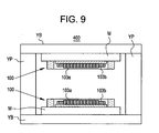
- Fig. 9 is a sectional view showing the major part of an MRI system in accordance with a second embodiment.
- An MRI system 400 is an open MRI system.
- a magnetic circuit comprising permanent magnets M vertically opposed to each other, base yokes YB, support yokes YP, and circular pole pieces 100 is used to induce a static magnetic field in a vertical direction between the circular pole pieces 100.
- a magnetic steel sheet instead of a magnetic steel sheet, a silicon steel sheet, a ferrite, an amorphous soft magnetic material, or any other soft magnetic material may be adopted.
Landscapes
- Physics & Mathematics (AREA)
- Condensed Matter Physics & Semiconductors (AREA)
- General Physics & Mathematics (AREA)
- Electromagnetism (AREA)
- Engineering & Computer Science (AREA)
- Power Engineering (AREA)
- Magnetic Resonance Imaging Apparatus (AREA)
- Manufacturing Cores, Coils, And Magnets (AREA)
Abstract
Description
- The present invention relates to a circular pole piece included in a magnetic circuit for magnetic resonance imaging (MRI), a method of manufacturing a laminate block employed in the circular pole piece, and an MRI system employing the circular pole piece.
- In the past, a circular pole piece included in a magnetic circuit for MRI has been shaped substantially circularly as a whole by arranging laminate blocks each of which has square or rectangular soft magnetic material tiles or heteromorphic soft magnetic material tiles, each of which is used to fill a gap among adjoining square or rectangular tiles, layered (see, for example, Fig. 1 in Patent Document 1). Otherwise, the circular pole piece has been shaped substantially circularly as a whole by arranging laminate blocks, each of which has trapezoidal or annularly sectoral soft magnetic material tiles layered, in the form of multiple concentric rings (see, for example, Fig. 21 in Japanese Unexamined Patent Publication No. 2000-200716
- Laminate blocks each having square or rectangular soft magnetic material tiles or heteromorphic soft magnetic material tiles, each of which is used to fill a gap among adjoining square or rectangular tiles, layered may be arranged to form a substantially circular pole piece. In this case, since the heteromorphic soft magnetic material tiles must be arranged, the work is complex and the cost of the pole piece is high.
- On the other hand, laminate blocks each having trapezoidal or annularly sectoral soft magnetic material tiles layered may be arranged in the form of multiple concentric rings in order to produce a substantially circular pole piece. In this case, there is a gap between adjoining rings or adjoining laminate blocks included in one ring. Moreover, in order to eliminate such a gap, trapezoidal or annularly sectoral soft magnetic material tiles of different sizes must be arranged. This leads to complex work and a high cost.
- The present invention seeks to provide a circular pole piece that contributes to simplification of work and a reduction in costs and that has no gap among adjoining laminate blocks, a method of manufacturing a laminate block employed in the circular pole piece, and an MRI system employing the circular pole piece.
- According to the first aspect of the present invention, there is provided a circular pole piece that is included in a magnetic circuit for MRI. The circular pole piece is shaped substantially circularly by arranging laminate blocks each of which has hexagonal soft magnetic material tiles layered.
- In the circular pole piece in accordance with the first embodiment, the soft magnetic material tiles are hexagonal. Therefore, the laminate blocks each having the soft magnetic material tiles layered can be arranged substantially circularly without a gap among adjoining blocks. Moreover, since a plurality of heteromorphic soft magnetic material tiles is unnecessary, work can be simplified and the cost of the circular pole piece can be reduced.
- According to the second aspect of the present invention, there is provided a circular pole piece having the same structure as the foregoing one. Herein, hexagonal directional magnetic steel sheet tiles that are identical to one another are layered with the directions of the axes of easy magnetization thereof varied by 60° so that they will have a non-directional property as a whole.
- The circular pole piece in accordance with the second aspect employs directional magnetic steel sheet tiles that exhibit a high permeability. This contributes to minimization of a residual magnetic induction. Moreover, the directional magnetic steel sheet tiles are layered with the directions of the axes of easy magnetization thereof varied by 60° so that they will have a non-directional property as a whole. A residual magnetic induction caused by switching of external magnetic fields can therefore be minimized irrespective of the direction of an external magnetic field (especially, the direction of a magnetic field gradient).
- According to the third aspect of the present invention, a circular pole piece has the same structure as the aforesaid ones. Herein, the laminate block has identical hexagonal directional magnetic steel sheet tiles layered with the directions of the axes of easy magnetization thereof varied by 60° so that the tiles will exhibit a non-directional property as a whole, and has a non-directional magnetic steel sheet tile, which is devoid of an axis of easy magnetization, layered in combination with the directional magnetic steel sheet tiles.
- The circular pole piece in accordance with the third aspect employs the directional magnetic steel sheet tiles exhibiting a high permeability. This results in a minimized residual magnetic induction. Moreover, the directional magnetic steel sheets are layered with the directions of the axes of easy magnetization thereof varied by 60° so that they will exhibit a non-directional property. Therefore, the residual magnetic induction can be minimized irrespective of the direction of an external magnetic field (especially, the direction of a magnetic field gradient). Furthermore, the non-directional magnetic steel sheet tile whose permeability is lower than that of the directional magnetic steel sheet tiles but which is inexpensive is layered in combination (in order to adjust the height of a laminate block). This results in the reduced cost of the circular pole piece.
- According to the fourth aspect of the present invention, the circular pole piece has the same structure as the aforesaid ones. Herein, the laminate block has non-directional magnetic steel sheet tiles devoid of an axis of easy magnetization layered.
- The circular pole piece in accordance with the fourth aspect employs the inexpensive non-directional magnetic steel sheet tiles. Consequently, the cost of the circular pole piece can be reduced.
- According to the fifth aspect of the present invention, a circular pole piece has the same structure. Herein, one side of a soft magnetic material tile is approximately 2.5 cm or less in length.
- In the circular pole piece in accordance with the fifth aspect, the maximum diameter of a soft magnetic material tile is approximately 5 cm or less. This is advantageous because the adverse effect of an eddy current derived from a magnetic field gradient can be suppressed.
- According to the sixth aspect of the present invention, a directional magnetic steel sheet having an axis of easy magnetization is hexagonally cut using a die in order to produce directional magnetic steel sheet tiles. A plurality of directional magnetic steel sheet tiles is layered with the axes of easy magnetization thereof turned by 60° so that the tiles will exhibit a non-directional property as a whole. The tiles are then integrated using an adhesive, through caulking, or using a rivet or screw.
- According to the sixth aspect, a laminate block to be employed in the circular pole piece in accordance with the second embodiment can be manufactured preferably.
- According to the seventh aspect of the present invention, a directional magnetic steel sheet having an axis of easy magnetization is hexagonally cut using a die in order to produce directional magnetic steel sheet tiles. A non-directional steel sheet devoid of an axis of easy magnetization is hexagonally cut using a die in order to produce non-directional magnetic steel sheet tiles. A plurality of directional magnetic steel sheet tiles is layered with the axes of easy magnetization thereof turned by 60° so that the tiles will exhibit a non-directional property as a whole. Moreover, the non-directional magnetic steel sheet tile is layered in combination with the directional magnetic steel sheet tiles. The resultant combination of directional magnetic steel sheet tiles and non-directional magnetic steel sheet tiles is integrated using an adhesive, through caulking, or using a rivet or screw.
- According to the seventh aspect, the laminate block employed in the circular pole piece in accordance with the third aspect can be manufactured preferably.
- According to the eighth aspect of the present invention, there is provided a laminate block manufacturing method. Herein, a non-directional magnetic steel sheet devoid of an axis of easy magnetization is hexagonally cut using a die in order to produce non-directional magnetic steel sheet tiles. A plurality of non-directional magnetic steel sheet tiles is layered, and integrated using an adhesive, through caulking, or using a rivet or screw.
- According to the eighth aspect, the laminate block employed in the circular pole piece in accordance with the fourth aspect can be manufactured preferably.
- According to the ninth aspect of the present invention, there is provided an MRI system including a circular pole piece that has the same structure as the aforesaid ones.
- In the MRI system in accordance with the ninth aspect, laminate blocks each having hexagonal soft magnetic material tiles layered can be arranged substantially circularly without a gap among adjoining blocks. Since heteromorphic soft magnetic material tiles are unnecessary, work can be simplified. Eventually, the cost of the circular pole piece can be reduced.
- According to a circular pole piece and an MRI system in which the present invention is implemented, heteromorphic soft magnetic material tiles are unnecessary. Therefore, work can be simplified and the cost of the circular pole piece can be reduced. Moreover, laminate blocks can be arranged substantially circularly without a gap among adjoining blocks.
- Moreover, according to a laminate block manufacturing method in which the present invention is implemented, a laminate block employed in the circular pole piece in accordance with the present invention can be manufactured preferably.
- The invention will now be described in greater detail, by way of example, with reference to the drawings, in which:-
- Fig. 1 is a plan view showing a circular pole piece in accordance with a first embodiment of the present invention.
- Fig. 2 is an A-A' sectional view of the circular pole piece shown in Fig. 1.
- Fig. 3 is a perspective view showing a first example of the laminate structure of a laminate block in accordance with the first embodiment.
- Fig. 4 is a perspective view showing a second example of the laminate structure of the laminate block in accordance with the first embodiment.
- Fig. 5 is a perspective view showing a second example of the laminate structure of the laminate block in accordance with the first embodiment.
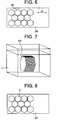
- Fig. 6 is an explanatory diagram showing a method of manufacturing directional magnetic steel sheet tiles.
- Fig. 7 is an explanatory diagram showing integration of a laminate block through bonding.
- Fig. 8 is an explanatory diagram showing a method of manufacturing non-directional magnetic steel sheet tiles.
- Fig. 9 is a front view showing the major part of an MRI system in accordance with a second embodiment.
- Fig. 10 is a top view showing a laminate block that is integrated with four magnetic steel sheet tiles through caulking.
- Fig. 11 is a side view showing the laminate block of Fig. 10.
- Fig. 12 is an expanded sectional view of the caulking when Fig.10 is viewed from side direction.
- Fig. 13 is a top view showing a laminate block that is integrated with four magnetic steel sheet tiles through using a rivet or a screw.
- Fig. 14 is a side view showing the laminate block of Fig.13.
- The present invention will be detailed in relation to illustrated embodiments below.
-
- Fig. 1 is a plan view showing a
circular pole piece 100 in accordance with a first embodiment. Fig. 2 is an A-A' sectional view of the circular pole piece shown in Fig. 1. - The
circular pole piece 100 comprises aring 101, a disk-like base 102 disposed inside thering 101 and made of a carbon steel, center-portion laminate blocks 103a arranged substantially circularly on the center portion of thebase 102, and marginal-portion laminate blocks 103b arranged like a doughnut on the marginal portion of thebase 102. - The height of the center-
portion laminate blocks 103a is, for example, 42 mm, and the height of the marginal-portion laminate blocks 103 is, for example, 36 mm. - Both the center-
portion laminate block 103a and marginal-portion laminate block 103b have a structure that hexagonal soft magnetic material tiles are layered. When the laminate structure is described, the center-portion laminate block 103a and marginal-portion laminate block 103b will not be discriminated from each other but will be called generically alaminate block 103. - Fig. 3 is an explanatory diagram showing a first example of the laminate structure of the
laminate block 103. - The
laminate block 103 is manufactured by repeatedly layering three hexagonal directional magneticsteel sheet tiles 60, each side of which has a length of 2.5 cm, with the directions of the axes of easy magnetization Ax thereof varied by 60° so that the tiles will exhibit a non-directional property as a whole. Incidentally, one side of the hexagonal directional magnetic steel sheet tile may have a length of 2.5 cm or less. - The thickness of the directional magnetic
steel sheet tile 60 is, for example, 0.35 mm. The center-portion laminate block 103a has 120 directional magneticsteel sheet tiles 60 layered, while the marginal-portion laminate block 103b has 102 directional magneticsteel sheet tiles 60 layered. - Fig. 4 is an explanatory diagram showing a second example of the laminate structure of the
laminate block 103. - The
laminate block 103 is manufactured by layering three hexagonal directional magneticsteel sheet tiles 60, each side of which has a length of 2.5 cm, with the directions of the axes of easy magnetization Ax thereof varied by 60°. Thereafter, one non-directional magneticsteel sheet tile 61 having the same shape as the directional magneticsteel sheet tiles 60 is layered in combination with the three directional magnetic steel sheet tiles. This process is repeated so that the laminate block will exhibit a non-directional property as a whole. - The thickness of the directional magnetic
steel sheet tile 60 and non-directional magneticsteel sheet tile 61 is, for example, 0.35 mm. Therefore, the center-portion laminate block 103a has 82 directional magneticsteel sheet tiles 60 and 27 non-directional magneticsteel sheet tiles 61 layered. The marginal-portion laminate block 103b has 77 directional magneticsteel sheet tiles 60 and 25 non-directional magneticsteel sheet tiles 61 layered. - Fig. 5 is an explanatory diagram showing a third example of the laminate structure of the
laminate block 103. - The
laminate block 103 is manufactured by layering hexagonal non-directional magneticsteel sheet tiles 61 each side of which has a length of 2.5 cm. - The thickness of the non-directional magnetic
steel sheet tile 61 is, for example, 0.35 mm. Therefore, the center-portion laminate block 103a has 120 non-directional magneticsteel sheet tiles 61 layered, while the marginal-portion laminate block 103b has 102 non-directional magneticsteel sheet tiles 61 layered. - The
laminate block 103 having the laminate structure shown in Fig. 3 is manufactured as described below. - First, as shown in Fig. 6, a directional magnetic steel sheet DS is cut using a die in order to produce numerous directional magnetic
steel sheet tiles 60. If degradation in a magnetic property caused by strain deriving from die cutting cannot be ignored, straightening annealing is carried out. - Thereafter, as shown in Fig. 3, a required number of directional magnetic
steel sheet tiles 60 is layered through internal-die caulking or the like in order to produce thelaminate block 103. - After the
laminate block 103 is immersed in an adhesive solution L, thelaminate block 103 is hardened and integrated so that it will not be disunited with application of electromagnetic force. - The
laminate block 103 having the laminate structure shown in Fig. 4 is manufactured as described below. - First, as shown in Fig. 6, a directional magnetic steel sheet DS is cut using a die in order to produce numerous directional magnetic
steel sheet tiles 60. If degradation in a magnetic property caused by strain deriving from die cutting cannot be ignored, straightening annealing is carried out. - Thereafter, as shown in Fig. 8, a non-directional magnetic steel sheet NS is cut using a die in order to produce numerous non-directional magnetic
steel sheet tiles 61. - Thereafter, as shown in Fig. 4, a required number of directional magnetic
steel sheet tiles 60 and a required number of non-directional magneticsteel sheet tiles 61 are layered in order to produce thelaminate block 103. - Thereafter, as shown in Fig. 7, the
laminate block 103 is immersed in an adhesive solution L, and then hardened and integrated. - The
laminate block 103 having the laminate structure shown in Fig. 5 is manufactured as described below. - First, as shown in Fig. 8, a non-directional magnetic steel sheet NS is cut using a die in order to produce numerous non-directional magnetic
steel sheet tiles 61. - Thereafter, as shown in Fig. 5, a required number of non-directional magnetic
steel sheet tiles 61 are layered in order to produce thelaminate block 103. - Thereafter, as shown in Fig. 7, the
laminate block 103 is immersed in an adhesive solution L, and then hardened and integrated. - According to the foregoing
circular pole piece 100, since heteromorphic soft magnetic material tiles are unnecessary, work can be simplified and the cost of the circular pole piece can be reduced. Moreover, the laminate blocks 103 can be arranged substantially circularly without a gap among adjoining blocks. Furthermore, since the maximum length of thelaminate block 103 is 5 cm, the adverse effect of an eddy current deriving from a magnetic field gradient can be minimized. - Fig. 10 is a top view showing a
laminate block 103 which has four layered magnetic steel sheet tiles 70 (directional magneticsteel sheet tiles 60 or non-directional magnetic steel sheet tiles 61) and which is integrated through caulking. Fig. 11 is a side view showing thelaminate block 103. Fig. 12 is an expanded sectional view showing acaulking point 72 when thelaminate block 103 is viewed from side direction. As shown in Figs. 10 through 12, the four layered magneticsteel sheet tiles 70 have threecaulking points 72 that are symmetrical to the center of the magneticsteel sheet tile 70, and they are integrated through caulking. - Incidentally, though Figs. 10 through 12 are an example of three
caulking points 72, caulking points that are symmetrical to the center of the magneticsteel sheet tile 70 may be six, twelve etc. - Fig. 13 is a top view showing a
laminate block 103 which has four layered magneticsteel sheet tiles 70 and which is integrated through using arivet 74 or ascrew 74. Fig. 14 is a side view showing thelaminate block 103. As shown in Figs. 13 and 14, therivet 74 or thescrew 74 pierces the four layered magneticsteel sheet tiles 70 and holds them. The four layered magneticsteel sheet tiles 70 are integrated through using therivet 74 or thescrew 74. - Incidentally, though Figs. 13 and 14 are an example of using a
rivet 74 or ascrew 74, rivets or screws that are placed symmetrical to the center of the magneticsteel sheet tile 70 may be three, six, twelve pieces etc. - Fig. 9 is a sectional view showing the major part of an MRI system in accordance with a second embodiment.
- An
MRI system 400 is an open MRI system. Herein, a magnetic circuit comprising permanent magnets M vertically opposed to each other, base yokes YB, support yokes YP, andcircular pole pieces 100 is used to induce a static magnetic field in a vertical direction between thecircular pole pieces 100. - Instead of a magnetic steel sheet, a silicon steel sheet, a ferrite, an amorphous soft magnetic material, or any other soft magnetic material may be adopted.
Claims (9)
- A circular pole piece included in a magnetic circuit for magnetic resonance imaging (MRI), wherein laminate blocks each of which has hexagonal soft magnetic material tiles layered are arranged so that the blocks will have a substantially circular shape as a whole.
- A circular pole piece according to Claim 1, wherein said laminate block has hexagonal directional magnetic steel sheet tiles, which are identical to one another, layered with the directions of the axes of easy magnetization thereof varied by 60° so that the tiles will exhibit a non-directional property as a whole.
- A circular pole piece according to Claim 2, wherein said laminate block has a non-directional magnetic steel sheet tile, which is devoid of an axis of easy magnetization, layered in combination with the directional magnetic steel sheet tiles.
- A circular pole piece according to Claim 1, wherein said laminate block has non-directional magnetic steel sheet tiles, which are devoid of an axis of easy magnetization, layered.
- A circular pole piece according to Claim 1, wherein one side of said soft magnetic material tile is approximately 2.5 cm or less in length.
- A laminate block manufacturing method comprising the steps of:hexagonally cutting a directional magnetic steel sheet, which has an axis of easy magnetization, using a die so as to produce directional magnetic steel sheet tiles;layering a plurality of directional magnetic steel sheet tiles with the axes of easy magnetization thereof turned by 60° so that the tiles will exhibit a non-directional property as a whole; andintegrating the tiles using an adhesive, through caulking, or using a rivet or screw.
- A laminate block manufacturing method comprising the steps of:hexagonally cutting a directional magnetic steel sheet, which has an axis of easy magnetization, using a die so as to produce directional magnetic steel sheet tiles;hexagonally cutting a non-directional magnetic steel sheet, which is devoid of an axis of easy magnetization, using a die so as to produce non-directional magnetic steel sheet tiles;layering a plurality of directional magnetic steel sheet tiles with the axes of easy magnetization thereof turned by 60° so that the tiles will exhibit a non-directional property as a whole, and layering the non-directional magnetic steel sheet tile in combination with the directional magnetic steel tiles; andintegrating the tiles using an adhesive, through caulking, or using a rivet or screw.
- A laminate block manufacturing method comprising the steps of:hexagonally cutting a non-directional magnetic steel sheet devoid of an axis of easy magnetization using a die so as to produce non-directional magnetic steel sheet tiles;layering a plurality of non-directional magnetic steel sheet tiles; andintegrating the tiles using an adhesive, through caulking, or using a rivet or screw.
- An MRI system employing a circular pole piece of any preceding Claim.
Applications Claiming Priority (4)
| Application Number | Priority Date | Filing Date | Title |
|---|---|---|---|
| JP2003033990 | 2003-02-12 | ||
| JP2003033990 | 2003-02-12 | ||
| JP2003380839A JP2004261585A (en) | 2003-02-12 | 2003-11-11 | Circular pole piece, method for manufacturing laminated block and mri apparatus |
| JP2003380839 | 2003-11-11 |
Publications (1)
| Publication Number | Publication Date |
|---|---|
| EP1447677A1 true EP1447677A1 (en) | 2004-08-18 |
Family
ID=32684284
Family Applications (1)
| Application Number | Title | Priority Date | Filing Date |
|---|---|---|---|
| EP04250742A Withdrawn EP1447677A1 (en) | 2003-02-12 | 2004-02-11 | Circular pole piece, laminate block manufacturing method and MRI system |
Country Status (5)
| Country | Link |
|---|---|
| US (1) | US6967481B2 (en) |
| EP (1) | EP1447677A1 (en) |
| JP (1) | JP2004261585A (en) |
| KR (1) | KR20040073342A (en) |
| CN (1) | CN1287396C (en) |
Cited By (2)
| Publication number | Priority date | Publication date | Assignee | Title |
|---|---|---|---|---|
| EP1447676A3 (en) * | 2003-02-12 | 2005-09-07 | GE Medical Systems Global Technology Company LLC | Circular pole piece and mri system |
| US8327543B2 (en) | 2007-11-29 | 2012-12-11 | Airbus Operations Sas | Wing mounting |
Families Citing this family (2)
| Publication number | Priority date | Publication date | Assignee | Title |
|---|---|---|---|---|
| CN101089649B (en) * | 2002-02-15 | 2010-06-02 | 日立金属株式会社 | Magnetic field generating apparatus manufacturing method |
| CN105390229B (en) * | 2015-12-10 | 2018-11-06 | 沈阳东软医疗系统有限公司 | A kind of permanent-magnet and the magnet apparatus for MRI system |
Citations (4)
| Publication number | Priority date | Publication date | Assignee | Title |
|---|---|---|---|---|
| GB1415209A (en) * | 1972-05-24 | 1975-11-26 | Unelec | Magnetic core for a polyphase transformer |
| EP0691548A1 (en) * | 1994-07-08 | 1996-01-10 | Sumitomo Special Metals Company Limited | Magnetic field generating device for use in MRI |
| EP1004888A1 (en) * | 1998-11-24 | 2000-05-31 | General Electric Company | Laminate tiles for an MRI system and method and apparatus for manufacturing the laminate tiles |
| US20020171526A1 (en) * | 2001-04-03 | 2002-11-21 | General Electric Company | Method and apparatus for magnetizing a permanent magnet |
Family Cites Families (6)
| Publication number | Priority date | Publication date | Assignee | Title |
|---|---|---|---|---|
| NL8502849A (en) * | 1985-10-18 | 1987-05-18 | Philips Nv | METHOD FOR APPLYING AN ADHESIVE ELECTRICAL INSULATING LAYER, METAL RIBBON COVERED WITH SUCH LAYER AND LOSING MAGNETIC CORE |
| JP2808198B2 (en) * | 1990-07-02 | 1998-10-08 | 住友特殊金属株式会社 | Magnetic field generator for MRI and its manufacturing method |
| EP0645641B1 (en) * | 1993-09-29 | 1999-06-16 | Oxford Magnet Technology Limited | Improvements in or relating to MRI magnets |
| JP3384944B2 (en) * | 1996-07-11 | 2003-03-10 | ジーイー横河メディカルシステム株式会社 | MRI equipment |
| JP3382868B2 (en) | 1998-12-22 | 2003-03-04 | ジーイー横河メディカルシステム株式会社 | Phase shift measuring method and MR imaging apparatus |
| JP4051301B2 (en) * | 2003-02-12 | 2008-02-20 | ジーイー・メディカル・システムズ・グローバル・テクノロジー・カンパニー・エルエルシー | Circular pole piece and MRI equipment |
-
2003
- 2003-11-11 JP JP2003380839A patent/JP2004261585A/en active Pending
-
2004
- 2004-02-11 US US10/776,879 patent/US6967481B2/en not_active Expired - Fee Related
- 2004-02-11 EP EP04250742A patent/EP1447677A1/en not_active Withdrawn
- 2004-02-11 KR KR1020040008886A patent/KR20040073342A/en not_active Withdrawn
- 2004-02-12 CN CNB200410032620XA patent/CN1287396C/en not_active Expired - Fee Related
Patent Citations (4)
| Publication number | Priority date | Publication date | Assignee | Title |
|---|---|---|---|---|
| GB1415209A (en) * | 1972-05-24 | 1975-11-26 | Unelec | Magnetic core for a polyphase transformer |
| EP0691548A1 (en) * | 1994-07-08 | 1996-01-10 | Sumitomo Special Metals Company Limited | Magnetic field generating device for use in MRI |
| EP1004888A1 (en) * | 1998-11-24 | 2000-05-31 | General Electric Company | Laminate tiles for an MRI system and method and apparatus for manufacturing the laminate tiles |
| US20020171526A1 (en) * | 2001-04-03 | 2002-11-21 | General Electric Company | Method and apparatus for magnetizing a permanent magnet |
Cited By (2)
| Publication number | Priority date | Publication date | Assignee | Title |
|---|---|---|---|---|
| EP1447676A3 (en) * | 2003-02-12 | 2005-09-07 | GE Medical Systems Global Technology Company LLC | Circular pole piece and mri system |
| US8327543B2 (en) | 2007-11-29 | 2012-12-11 | Airbus Operations Sas | Wing mounting |
Also Published As
| Publication number | Publication date |
|---|---|
| US20040160222A1 (en) | 2004-08-19 |
| JP2004261585A (en) | 2004-09-24 |
| CN1287396C (en) | 2006-11-29 |
| KR20040073342A (en) | 2004-08-19 |
| US6967481B2 (en) | 2005-11-22 |
| CN1525501A (en) | 2004-09-01 |
Similar Documents
| Publication | Publication Date | Title |
|---|---|---|
| US5283544A (en) | Magnetic field generating device used for MRI | |
| US3710291A (en) | Permanent magnet | |
| EP0691548A1 (en) | Magnetic field generating device for use in MRI | |
| EP1889087B1 (en) | Permanent magnet for magnetic resonance imaging | |
| EP1127359B1 (en) | Bulk amorphous metal magnetic components | |
| EP1365498A3 (en) | Voice coil linear actuator, apparatus using the actuator, and method for manufacturing the actuator | |
| US20080290741A1 (en) | Planar motor | |
| JP4758629B2 (en) | Multi-ring permanent magnet without pole piece and method for manufacturing the same | |
| EP3125257B1 (en) | Dipole ring magnetic field generator | |
| US6967481B2 (en) | Circular pole piece, laminate block manufacturing method, and MRI system | |
| US20130009735A1 (en) | Permanent magnet options for magnetic detection and separation - ring magnets with a concentric shim | |
| US6838966B2 (en) | Circular pole piece and MRI system | |
| EP1411366A3 (en) | Gradient coil set with variable field of view | |
| JPH05182821A (en) | Magnetic field generator for mri | |
| EP0541872B1 (en) | Magnetic field generating apparatus for MRI | |
| JP2019193404A (en) | Magnetization apparatus, method for manufacturing magnet structure, and method for manufacturing rotary electric machine | |
| EP1542243B1 (en) | Magnetic circuit with opposing permanent magnets | |
| US11482899B2 (en) | Rotating electrical machine with rotor having arc shaped permanent magnets | |
| JPH04138131A (en) | Magnetic field generation device for mri | |
| JP6612713B2 (en) | Assembly method of magnetized yoke | |
| EP1465216A1 (en) | Methods and apparatus for positioning permanent magnetic blocks | |
| WO2004104612A1 (en) | Magnetic field generating system applicable to nuclear magnetic resonance device | |
| CN1611961B (en) | Imaging system comprisign at least one lamination of pole and magnetic resonance imaging systems | |
| KR20160149908A (en) | Magnetic chuck for t-slot is provided | |
| JPH0287505A (en) | Magnetic field generating equipment for mri use |
Legal Events
| Date | Code | Title | Description |
|---|---|---|---|
| PUAI | Public reference made under article 153(3) epc to a published international application that has entered the european phase |
Free format text: ORIGINAL CODE: 0009012 |
|
| AK | Designated contracting states |
Kind code of ref document: A1 Designated state(s): AT BE BG CH CY CZ DE DK EE ES FI FR GB GR HU IE IT LI LU MC NL PT RO SE SI SK TR |
|
| AX | Request for extension of the european patent |
Extension state: AL LT LV MK |
|
| RIN1 | Information on inventor provided before grant (corrected) |
Inventor name: SAKO, TAKESHI5TH FLOOR, YURAKUCHO DENKI BLD-NORTH Inventor name: CHONAN, HIROYUKI5.FLOOR,YURAKUCHO DENKI BLD-NORTH Inventor name: SAKUMA, MASAAKI Inventor name: INOUE, YUJI |
|
| 17P | Request for examination filed |
Effective date: 20050218 |
|
| AKX | Designation fees paid |
Designated state(s): DE FR GB |
|
| RBV | Designated contracting states (corrected) |
Designated state(s): DE FR GB |
|
| 17Q | First examination report despatched |
Effective date: 20110331 |
|
| STAA | Information on the status of an ep patent application or granted ep patent |
Free format text: STATUS: THE APPLICATION IS DEEMED TO BE WITHDRAWN |
|
| 18D | Application deemed to be withdrawn |
Effective date: 20110811 |