EP1447426A1 - Rubber composition pneumatic tire and method of manufacturing the pneumatic tire - Google Patents
Rubber composition pneumatic tire and method of manufacturing the pneumatic tire Download PDFInfo
- Publication number
- EP1447426A1 EP1447426A1 EP02768119A EP02768119A EP1447426A1 EP 1447426 A1 EP1447426 A1 EP 1447426A1 EP 02768119 A EP02768119 A EP 02768119A EP 02768119 A EP02768119 A EP 02768119A EP 1447426 A1 EP1447426 A1 EP 1447426A1
- Authority
- EP
- European Patent Office
- Prior art keywords
- rubber
- resin
- pneumatic tire
- foamed rubber
- foaming agent
- Prior art date
- Legal status (The legal status is an assumption and is not a legal conclusion. Google has not performed a legal analysis and makes no representation as to the accuracy of the status listed.)
- Granted
Links
Images





Classifications
-
- B—PERFORMING OPERATIONS; TRANSPORTING
- B60—VEHICLES IN GENERAL
- B60C—VEHICLE TYRES; TYRE INFLATION; TYRE CHANGING; CONNECTING VALVES TO INFLATABLE ELASTIC BODIES IN GENERAL; DEVICES OR ARRANGEMENTS RELATED TO TYRES
- B60C11/00—Tyre tread bands; Tread patterns; Anti-skid inserts
- B60C11/14—Anti-skid inserts, e.g. vulcanised into the tread band
-
- B—PERFORMING OPERATIONS; TRANSPORTING
- B29—WORKING OF PLASTICS; WORKING OF SUBSTANCES IN A PLASTIC STATE IN GENERAL
- B29D—PRODUCING PARTICULAR ARTICLES FROM PLASTICS OR FROM SUBSTANCES IN A PLASTIC STATE
- B29D30/00—Producing pneumatic or solid tyres or parts thereof
- B29D30/06—Pneumatic tyres or parts thereof (e.g. produced by casting, moulding, compression moulding, injection moulding, centrifugal casting)
- B29D30/52—Unvulcanised treads, e.g. on used tyres; Retreading
-
- B—PERFORMING OPERATIONS; TRANSPORTING
- B60—VEHICLES IN GENERAL
- B60C—VEHICLE TYRES; TYRE INFLATION; TYRE CHANGING; CONNECTING VALVES TO INFLATABLE ELASTIC BODIES IN GENERAL; DEVICES OR ARRANGEMENTS RELATED TO TYRES
- B60C11/00—Tyre tread bands; Tread patterns; Anti-skid inserts
-
- C—CHEMISTRY; METALLURGY
- C08—ORGANIC MACROMOLECULAR COMPOUNDS; THEIR PREPARATION OR CHEMICAL WORKING-UP; COMPOSITIONS BASED THEREON
- C08L—COMPOSITIONS OF MACROMOLECULAR COMPOUNDS
- C08L21/00—Compositions of unspecified rubbers
-
- B—PERFORMING OPERATIONS; TRANSPORTING
- B29—WORKING OF PLASTICS; WORKING OF SUBSTANCES IN A PLASTIC STATE IN GENERAL
- B29C—SHAPING OR JOINING OF PLASTICS; SHAPING OF MATERIAL IN A PLASTIC STATE, NOT OTHERWISE PROVIDED FOR; AFTER-TREATMENT OF THE SHAPED PRODUCTS, e.g. REPAIRING
- B29C44/00—Shaping by internal pressure generated in the material, e.g. swelling or foaming ; Producing porous or cellular expanded plastics articles
-
- B—PERFORMING OPERATIONS; TRANSPORTING
- B60—VEHICLES IN GENERAL
- B60C—VEHICLE TYRES; TYRE INFLATION; TYRE CHANGING; CONNECTING VALVES TO INFLATABLE ELASTIC BODIES IN GENERAL; DEVICES OR ARRANGEMENTS RELATED TO TYRES
- B60C11/00—Tyre tread bands; Tread patterns; Anti-skid inserts
- B60C11/14—Anti-skid inserts, e.g. vulcanised into the tread band
- B60C2011/147—Foamed rubber or sponge rubber on the tread band
-
- Y—GENERAL TAGGING OF NEW TECHNOLOGICAL DEVELOPMENTS; GENERAL TAGGING OF CROSS-SECTIONAL TECHNOLOGIES SPANNING OVER SEVERAL SECTIONS OF THE IPC; TECHNICAL SUBJECTS COVERED BY FORMER USPC CROSS-REFERENCE ART COLLECTIONS [XRACs] AND DIGESTS
- Y10—TECHNICAL SUBJECTS COVERED BY FORMER USPC
- Y10S—TECHNICAL SUBJECTS COVERED BY FORMER USPC CROSS-REFERENCE ART COLLECTIONS [XRACs] AND DIGESTS
- Y10S152/00—Resilient tires and wheels
- Y10S152/03—Slits in threads
-
- Y—GENERAL TAGGING OF NEW TECHNOLOGICAL DEVELOPMENTS; GENERAL TAGGING OF CROSS-SECTIONAL TECHNOLOGIES SPANNING OVER SEVERAL SECTIONS OF THE IPC; TECHNICAL SUBJECTS COVERED BY FORMER USPC CROSS-REFERENCE ART COLLECTIONS [XRACs] AND DIGESTS
- Y10—TECHNICAL SUBJECTS COVERED BY FORMER USPC
- Y10T—TECHNICAL SUBJECTS COVERED BY FORMER US CLASSIFICATION
- Y10T428/00—Stock material or miscellaneous articles
- Y10T428/249921—Web or sheet containing structurally defined element or component
- Y10T428/249953—Composite having voids in a component [e.g., porous, cellular, etc.]
- Y10T428/249971—Preformed hollow element-containing
- Y10T428/249972—Resin or rubber element
-
- Y—GENERAL TAGGING OF NEW TECHNOLOGICAL DEVELOPMENTS; GENERAL TAGGING OF CROSS-SECTIONAL TECHNOLOGIES SPANNING OVER SEVERAL SECTIONS OF THE IPC; TECHNICAL SUBJECTS COVERED BY FORMER USPC CROSS-REFERENCE ART COLLECTIONS [XRACs] AND DIGESTS
- Y10—TECHNICAL SUBJECTS COVERED BY FORMER USPC
- Y10T—TECHNICAL SUBJECTS COVERED BY FORMER US CLASSIFICATION
- Y10T428/00—Stock material or miscellaneous articles
- Y10T428/249921—Web or sheet containing structurally defined element or component
- Y10T428/249953—Composite having voids in a component [e.g., porous, cellular, etc.]
- Y10T428/249976—Voids specified as closed
- Y10T428/249977—Specified thickness of void-containing component [absolute or relative], numerical cell dimension or density
Definitions
- This invention relates to a rubber composition of a foamed rubber providing a large friction force even on a body having, for example, an ice face of a low friction coefficient, and a pneumatic tire having improved steering stability performances such as braking performance, cornering performance and the like by applying this rubber composition to an upper-layer rubber part of a tread rubber constituting at least a ground contact face to enhance a gripping force on a frozen road surface or a snow covered road surface, particularly a winter-seasoned tire such as a studless tire or the like as well as a method of producing such a tire.
- the microscopic grooves formed on the tread are liable to be crushed as a load applied to the tire becomes large, and hence the effect of increasing the friction coefficient on the ice-snow road surface can not be sufficiently obtained.
- the short fibers are embedded in the foamed rubber at a state of extending in a straight line and substantially in parallel to a worn face of the tread when the tread is worn by the running for rapidly breaking away the short fibers exposed on the worn face of the tread to microscopically form the grooves.
- the short fibers are actually and frequently embedded in the foamed rubber at a state of being curled through heat shrinkage in the vulcanization or pushing the fibers into a groove portion of a mold part or a sipe portion to bend in the tread rubber.
- the short fibers not extending substantially in parallel to the worn face of the tread can not easily be broken away from the foamed rubber, so that the microscopic grooves as originally intended can not be formed efficiently.
- ice or snow on the ice-snow road surface is thawed to water by friction heat when the tire tread contacts with the ice-snow road surface and this water forms a water membrane between the tread and the ice-snow road surface, and the performances on ice or performances on snow are deteriorated by this water membrane.
- the water membrane can be removed by the action of irregularities on the tread formed by the closed cells, and hence it is attempted to improve the performances on ice or the performances on snow.
- drainage paths can be particularly formed by the continuous closed cells, whereby the water removing effect is enhanced.
- the first invention is a rubber composition constituted with a foamed rubber, characterized in that the foamed rubber has continuous cells each continuously extending substantially along a particular direction and sealed with a resin protection membrane.
- the foamed rubber comprises resin cords continuously extending in a thready form along a particular direction before vulcanization and a foaming agent, in which the resin cord is melted in the vulcanization to develop a viscosity lower than that of rubber constituting the foamed rubber and the foaming agent has a property of foaming in the vulcanization to produce gases, and the continuous cell is formed by sealing at least a part of gases produced from the foaming agent with the resin protection membrane made of the resin cord.
- the second invention is a pneumatic tire comprising a tread rubber, at least an upper-layer rubber part of which forming a ground contact face being made of a foamed rubber, characterized in that the upper-layer rubber part has toroidally continuous cells each continuously extending substantially along a circumferential direction of the tire and sealed with a resin protection membrane.
- the foamed rubber comprises resin cords each continuously extending in a thready form along the circumferential direction of the tire before vulcanization and a foaming agent, in which the resin cord is melted in the vulcanization to develop a viscosity lower than that of rubber constituting the upper-layer rubber part and the foaming agent has a property of foaming in the vulcanization to produce gases, and the continuous cell is formed by sealing at least a part of gases produced from the foaming agent with the resin protection membrane made of the resin cord.
- the continuous cells are arranged at plural stages in a thickness direction of the tread.
- the resin cord is preferable to have a cord diameter of 10-100 ⁇ m and/or to have a melting point lower than a maximum vulcanization temperature of the tread rubber.
- the foamed rubber is preferable to have long cells of 0.5-5 mm in length in addition to the above continuous cells, in which these long cells are arranged so as to connect with the continuous cells in a network form and/or to have an existing ratio of all bubbles contained in its interior of 10-40% as a weight ratio and HD (hardness) of 38-58.
- HD(hardness) used herein means a scale reading of a durometer hardness as measured at a testing temperature of 20°C by a type-A durometer hardness testing machine defined in JIS K6253-1993.
- the upper-layer rubber part is preferable to have a thickness corresponding to 30-70% of a thickness of the tread rubber.
- the third invention is a method of producing a pneumatic tire which comprises covering one or plural resin cords arranged in parallel to each other with a foamed rubber containing a foaming agent to form a sheet-like member having a given width, winding and laminating the sheet-like member on a green case or a shaping drum along a circumferential direction of the green case or the shaping drum to form an upper-layer rubber part constituting a tread rubber and vulcanizing, during which the resin cord is melted to form a resin protection membrane and at least a part of gases produced by foaming of the foaming agent contained in the foamed rubber is sealed with the resulting resin protection membrane to form toroidally continuous cells each continuously extending substantially along a circumferential direction of the tire in the foamed rubber constituting the upper-layer rubber part.
- the sheet-like member is preferable to be formed by drawing one or plural resin cords and covering such drawn resin cords with the foamed rubber through an insulation system, or by sandwiching one or plural resin cords arranged in parallel to each other between two foamed rubber sheets, or by surrounding and laminating one or plural resin cords with cord-shaped rubbers containing a foaming agent and covering with rubber through an inserter.
- the fourth invention is a method of producing a pneumatic tire which comprises winding and laminating a narrow-width ribbon-shaped member of at least one resin cord covered with a foamed rubber containing a foaming agent on a green case or a shaping drum along a circumferential direction of the green case or the shaping drum to form an upper-layer rubber part constituting a tread rubber and vulcanizing, during which the resin cord is melted to form a resin protection membrane and at least a part of gases produced by foaming of the foaming agent contained in the foamed rubber is sealed with the resulting resin protection membrane to form toroidally continuous cells each continuously extending substantially along a circumferential direction of the tire in the foamed rubber constituting the upper-layer rubber part.
- the ribbon-shaped member is preferable to be formed by drawing one or plural resin cords and covering such drawn resin cords with the foamed rubber through an insulation system, or by surrounding and laminating one or plural resin cords with cord-shaped rubbers containing a foaming agent and covering with rubber through an inserter.
- At least the upper-layer rubber part of the tread rubber is preferable to be formed by winding and laminating the ribbon-shaped member so as to overlap widthwise end portions with each other every winding while shifting in the widthwise direction of the tire.
- the fifth invention is a method of producing a pneumatic tire which comprises winding and laminating a ribbon-shaped rubber sheet containing a foaming agent and resin cords on a green case or a shaping drum so as to arrange the resin cords at a given interval along a circumferential direction of the green case or the shaping drum to form an upper-layer rubber part constituting a tread rubber and vulcanizing, during which the resin cord is melted to form a resin protection membrane and at least a part of gases produced by foaming of the foaming agent contained in the foamed rubber is sealed with the resulting resin protection membrane to form toroidally continuous cells each continuously extending substantially along a circumferential direction of the tire in the foamed rubber constituting the upper-layer rubber part.
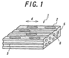
- FIG. 1 shows an example of a rubber composition 1 according to the first invention.
- a main feature in the construction of the rubber composition 1 according to the first invention lies in the rationalization of a bubble existing state in a foamed rubber constituting the rubber composition 1, concretely the formation of continuous cells 6 in the foamed rubber, each continuously extending substantially along a particular direction 4, a longitudinal direction of the rubber composition 1 in FIG. 1 and sealed with a resin protection membrane 5.
- this construction can be formed drainage paths 8 when the continuous cells 6 are opened at the ground contact face of the tread portion.
- a large friction force is always obtained by a water removing action of the drainage path 8.
- the foamed rubber constituting the rubber composition 1 is preferable to comprise resin cords 7 (see FIG. 2(a)) each continuously extending in a thready form along the particular direction 4 before vulcanization and a foaming agent for forming the continuous cells 6, in which the resin cord is melted in the vulcanization to develop a viscosity lower than that of rubber part constituting the foamed rubber and the foaming agent has a property of foaming in the vulcanization to produce gases, and the continuous cell 6 is formed by sealing at least a part of gases produced from the foaming agent with the resin protection membrane made of the resin cord.
- FIGS. 2(a)-(d) are views illustrating a process of forming the continuous cell 6 in the foamed rubber.
- FIG. 2(a) shows a state of the foamed rubber when the heating of the foamed rubber is started in a mold (not shown).
- the foaming agent in the foamed rubber is gasified by the heating to start the generation of bubbles 2'.
- a resin 7 is melted (or softened) and a viscosity thereof is made lower than a viscosity of a rubber part 3'.
- a higher temperature e.g. a maximum vulcanization temperature
- the bubbles 2' entered into the molten resin 7' are connected to each other in a chain in the resin 7' and finally sealed with a resin protection membrane 5 to form a continuous cell 6.
- the bubbles 2' generated apart from the resin 7' in the rubber part 3' settle on their positions at a state of a spherical closed cell.
- the spherical closed cells 2 and the continuous cells 6 reinforced with the resin protection membranes 5 can be formed in the foamed rubber constituting the rubber composition 1 of the first invention as shown in FIGS. 2(c) and 2(d).
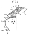
- FIG. 3 shows a widthwise left-half section of a pneumatic tire 10 according to the second invention.
- the illustrated pneumatic tire 10 is a studless tire and comprises a tread portion 11, a pair of sidewall portions 12, a pair of bead portions 13, a carcass 15 of one ply toroidally extending between a pair of bead cores 14 each embedded in the bead portion 13 and fixed at both end portions around the bead core, and a belt 16 of two rubberized cord layers 16a, 16b arranged between a crown portion of the carcass and the tread portion 11.
- the tread portion 11 is made of two layers, i.e. a lower-layer rubber part 17 made of a relatively hard rubber and an upper-layer rubber part 18 applied with the same foamed rubber as the rubber composition according to the first invention.
- tread grooves i.e. tread grooves having plural circumferential grooves 20 extending along a circumferential direction 19 of the tire and plural lateral grooves 21 intersecting therewith in FIG. 3 are arranged on the tread portion 11, whereby a tread land portion is divided into a plurality of block land parts 22.
- a plurality of sipes 23 are arranged on each of the block land parts 22 as an edge component for ensuring performances on an ice-snow road surface.
- tread groove used herein includes all grooves arranged on the tread portion 11. For example, there are mentioned slant grooves (not shown) inclined with respect to the circumferential direction 19 of the tire and the like in addition to the aforementioned circumferential grooves 20 and lateral grooves 21.
- a main feature in the construction of the pneumatic tire 10 according to the second invention lies in that the upper-layer rubber part 18 is made of the rubber composition 1 shown in FIG. 1, more concretely the upper-layer rubber part 18 has the continuous cells 6 each continuously extending substantially along the circumferential direction 19 of the tire and sealed with the resin protection membrane 5.
- this construction can be enhanced the gripping force on a frozen road surface or a snow covered road surface to improve steering stability performances such as braking performance, cornering performance and the like.
- FIGS. 4(a), (b) show one of the block land parts 22 constituting the tread portion worn by the running, wherein (a) is a widthwise section view and (b) is a perspective view.
- the tire 10 has a toroidal form, so that the continuous cells 6 are toroidally extended substantially along the circumferential direction 19 of the tire.
- drainage paths 24 extending in the circumferential direction 19 of the tire are always formed on the ground contact face of the tread portion in the tire 10 by opening the continuous cells 6 each sealed with the resin protection membrane 5 through the wearing of the tread. Furthermore, these drainage paths 24 communicate with the plural lateral grooves 21 defining the block land part and also communicate with the plural sipes 23 arranged in the same block land part, so that there can be obtained good water removing effect.
- the foamed rubber comprises resin cords 7 continuously extending in a thready form along the circumferential direction 19 of the tire before vulcanization and a foaming agent for forming the continuous cells 6, in which the resin cord 7 is melted in the vulcanization to develop a viscosity lower than that of rubber part 3' constituting the foamed rubber and the foaming agent has a property of foaming in the vulcanization to produce gases, and the continuous cell 6 is formed by sealing at least a part of gases produced from the foaming agent with the resin protection membrane 5 made from the resin cord 7 (see FIG. 2).
- the resin cords 7 are arranged in a density of about one cord/1 mm for the purpose of removing water in the circumferential direction 19 of the tire.
- a cord diameter of the resin cord is preferable to be 10-100 ⁇ m in view of the securement of actual contact area.
- the continuous cells 6 are preferable to be arranged regularly or randomly at plural stages in not only the widthwise direction of the tire but also the thickness direction of the tread as shown in FIGS. 4(a) and (b). By arranging the continuous cells 6 as mentioned above, the drainage paths 24 can be always existent on the ground contact face of the tread portion in the wearing.
- the upper-layer rubber part 18 is preferable to have long cells 26 of 0.5-5 mm in length in addition to the above continuous cells 6, in which these long cells 26 are arranged so as to connect with the continuous cells 6 in a network form as shown in FIG. 5 in view of the shortening of the time required in the drainage or the increase of the drainage efficiency.
- the long cells 26 in the upper-layer rubber part 18 it is preferable to use a method wherein long resin pieces 37 are kneaded with an uncured rubber composition 38 in an extruder 39 and a kneaded mass is extruded through a die 40 of the extruder into a given shape as shown in FIG. 10 and then the resulting sheet-shaped rubber member 41 is used as a starting material for the upper-layer rubber part 18 and thereafter foamed through vulcanization.
- the resin cord is required to have a melting point lower than a maximum vulcanization temperature of the tread rubber itself because it forms the resin protection membrane 5 sealing the continuous cell 6 therein in a tire product.
- the melting point is made preferably by 10°C or more, particularly 30°C or more than the maximum vulcanization temperature.
- the melting of the resin cord 7 starts at a last stage of the vulcanization and the rubber part already takes a greater amount of gases therein to promote cross-linking reaction and hence an amount of gas captured in the molten resin cord becomes small and the formation of the continuous cell 6 is difficult
- the difference between the melting point of the resin cord 7 and the maximum vulcanization temperature is too large (concretely the melting point of the resin cord is low)
- the resin cords 7 are melted by heat in the kneading of rubber and the fusion bonding between the molten resin cords 7' is caused at this kneading stage and it is difficult to extend the continuous cells 6 along the circumferential direction 19 of the tire.
- maximum vulcanization temperature of tread rubber itself used herein means a maximum temperature of the tread portion in the vulcanization inside a mold for a period ranging up to the cooling of the tire outside the mold.
- the upper-layer rubber part 18 is preferable to have a thickness corresponding to 30-70%, more preferably 40-55% of a thickness of the tread rubber.
- the thickness of the upper-layer rubber part 18 is less than 30% of the thickness of the tread rubber, the foamed rubber constituting the upper-layer rubber part 18 becomes not existent at the last use stage of the tire and it is difficult to ensure the stable performances on ice-snow road in the service life of the tire, while when it exceeds 70%, the rigidity of the tread portion is apt to be lacking and there is caused a fear that the steering stability in usual running (running on dry road surface) can not be sufficiently ensured.
- the foamed rubber constituting the upper-layer rubber part 18 is preferable that an existing ratio of all bubbles contained therein is a range of 10-40% as a weight ratio and HD is 38-58.
- the existing ratio of all bubbles contained in the interior of the foamed rubber is less than 10% as a weight ratio, the drainage efficiency lowers, while when it exceeds 40%, the wear resistance and the performances on ordinary road are deteriorated.
- HD of the foamed rubber is less than 38, the wear resistance and the performances on ordinary road are deteriorated, while when it exceeds 58, the tire hardly follows to micro-irregularities on ice road.
- the continuous cell 6 is preferable to have a sectional diameter of 10-200 ⁇ m.
- the sectional diameter is less than 10 ⁇ m, the drainage efficiency is insufficient, while it exceeds 200 ⁇ m, the actual contact area lowers and hence the friction coefficient on ice lowers.
- the method of forming the upper-layer rubber part 18 according to the third invention is explained.
- one or plural resin cords are arranged in parallel and covered with foamed rubber containing a foaming agent to form a sheet-like member having a given width.
- the term "given width” used herein means the same width as a tread rubber.
- FIG. 6(a) shows an example of a method of forming a sheet-like member 30.
- This figure shows a case that one or plural resin cords 7 are drawn out from a respective bobbin(s) 31 and the drawn resin cords 7 are arranged in parallel and covered with foamed rubbers 33a, 33b extruded through two rubber extruders 32a, 32b through an insulation system, which is then passed through an inserter 34 to integrally unite the resin cords 7 and the foamed rubbers 33a, 33b with each other to thereby form a sheet-like member 30.
- the sheet-like member 30 may be formed by covering the resin cords 7 through a single rubber extruder.
- the formation method of the sheet-like member 30 is not limited to the above and various formation methods can be adopted.
- the sheet-like member 30 is preferable to be formed by placing resin cords 7A, 7B, 7C Vietnamese having a length equal to a peripheral length of a green case extruded through an extruding machine 42 on a foamed rubber sheet 33b side by side and placing another foamed rubber sheet 33a thereon to sandwich the resin cords 7A, 7B, 7C ... between the foamed rubber sheets 33a, 33b.
- the sheet-like member 30 is wound and laminated on a green case or a shaping drum, which is previously wound and laminated with a rubber sheet constituting a lower-layer rubber part 17, a shaping drum 35 in FIG. 8 so as to extend the resin cords 7 embedded in the sheet-like member 30 along a circumferential direction of the shaping drum 35 to thereby form the upper-layer rubber part 18.
- the upper-layer rubber part 18 is formed by using a narrow-width ribbon-shaped member obtained by covering at least one resin cord with a foamed rubber containing a foaming agent.
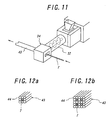
- FIG. 11 is a view illustrating an example of the method of forming a ribbon-shaped member 43.
- one resin cord 7 is covered with a foamed rubber extruded from a rubber extruder 32 through an insulation system and passed through an inserter 34 to cover the resin cord 7 with the foamed rubber to thereby form a ribbon-shaped member 43.
- the ribbon-shaped member 43 may be formed by laminating plural cord-shaped rubbers 44 containing a foaming agent around one resin cord 7 and passing through the inserter to cover the resin cord 7 with rubber as shown in FIG. 12(a), or by laminating plural cord-shaped rubbers 44 containing a foaming agent around each of plural resin cords 7 and passing through the inserter to cover the resin cords 7 with rubber as shown in FIG. 12(b).
- the ribbon-shaped member 43 is wound and laminated on a green case or a shaping drum, which is previously wound and laminated with a rubber sheet constituting a lower-layer rubber part 17, so as to extend the resin cords 7 embedded in the ribbon-shaped member 43 along a circumferential direction of the shaping drum to thereby form the upper-layer rubber part 18.
- At least the upper-layer rubber part 18 of the tread rubber may be formed by winding and laminating the ribbon-shaped member 43 so as to overlap width end portions with each other every winding while shifting in the widthwise direction 36 of the tire.
- the continuous cells 6 can be effectively arranged in not only the widthwise direction of the tread but also the thickness direction of the tread, so that as the tire is worn, the drainage paths 24 formed by opening the continuous cells 6 can be always existent in the ground contact face of the tread portion 11 and hence the lowering of the performances on ice-snow during the wearing can be suppressed.
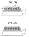
- a cord-shaped rubber 44 is wound on the lower-layer rubber part 17 while shifting in the widthwise direction 36 of the tire to form a single rubber layer 45. Then, plural resin cords 7 and the cord-shaped rubber 44 are wound on t he single rubber layer 45 so as to arrange the resin cords 7 at given intervals to form a cord-rubber layer 46.
- the single rubber layer 45 and the cord-rubber layer 46 are successively laminated to obtain a given thickness to thereby form the upper-layer rubber part 18.
- this figure shows a case that the single rubber layer 45 is formed with the plural cord-shaped rubbers 44, but the single rubber layer 45 may be constituted with a single wide-width rubber sheet as shown in FIG. 13(b).
- the resin cords 7 in the foamed rubber constituting the upper-layer rubber part of the tire tread are melted to form the resin protection membrane 5 and at the same time at least a part of gases produced by foaming the foaming agent contained in the foamed rubber is sealed with the rein protection membrane 5, whereby there can be formed the continuous cells 6 each continuously extending substantially along the circumferential direction 19 of the tire.
- the studless tire according to the second invention is prepared by the method according to the third invention applying the rubber composition according to the first invention to the upper-layer rubber part and the performances thereof are evaluated below.
- Tires of Examples 1-9 are studless radial tires each having a half section in a widthwise direction of the tire shown in FIG. 3 and a tire size of 205/65R15, in which continuous cells are arranged in an upper-layer rubber part at 5 stages and 30 rows with an interval of 1 mm and a thickness of the upper-layer rubber part is 45% of a thickness of a tread rubber and an existing ratio of all bubbles contained in an interior of a foamed rubber constituting the upper-layer rubber part as a weight ratio and HD of the foamed rubber are shown in Table 1.
- the upper-layer rubber part is formed by winding and laminating a narrow-width ribbon-shaped member having a thickness of 0.5 mm and a width of 10 mm so as to overlap widthwise end portion with each other every winding while shifting in the widthwise direction of the tire as shown in FIG. 9.
- the resin cords are arranged in the ribbon-shaped member at a density of 1.5 cords/1 mm.
- the resin cord embedded in the ribbon-shaped member before vulcanization has a cord diameter of 30 ⁇ m and a melting point of 140°C, which is lower by about 30°C than a maximum vulcanization temperature of the tread rubber itself.
- the other construction of the tire is substantially the same as in the ordinary pneumatic radial tire for a passenger car.
- the tire of Conventional Example is the same as the tire of Example 1 except that the foamed rubber constituting the upper-layer rubber part has an expansion ratio of 26% as a weight ratio of rubber, HD of 48 and a thickness corresponding to 45% of a whole of a tread and the continuous cells are not formed.
- Each of the above tires is assembled into a rim of 6.5J ⁇ 15 to form a tire-rim assembly, which is mounted onto a passenger car.
- a passenger car is run on various road surfaces (dry road surface, wet road surface, frozen road surface, snow covered road surface) to evaluate braking performances on the frozen road surface and snow covered road surface, and steering stability performances on the dry road surface and wet road surface.
- a tire internal pressure is 190 kPa in front and rear tires, and a load corresponds to two crewmen.
- the braking performance is evaluated by measuring a stopping distance when quick braking (full braking) is applied from a speed of 20 km/h on the frozen road surface or 40 km/h on the snow covered road surface at an OFF state of ABS (anti-lock braking system).
- the steering stability performance is evaluated by measuring an average time every running when the tire is run on a circuit course 10 times.
- the example tires are equal level in the steering stability performance on the dry and wet road surfaces but are considerably excellent in the braking performances on the frozen and snow covered road surfaces as compared with the conventional tire.
- a rubber composition providing a large friction force even on a body having, for example, an ice face of a low friction coefficient by constituting with a foamed rubber having a rationalized foaming state, and a pneumatic tire, particularly a winter-seasoned tire such as a studless tire having improved steering stability performances such as braking performance, cornering performance and the like by applying this rubber composition to an upper-layer rubber part of a tread rubber constituting at least a ground contact face to enhance a gripping force on a frozen road surface or a snow covered road surface as well as a method of producing such a tire.
Landscapes
- Engineering & Computer Science (AREA)
- Mechanical Engineering (AREA)
- Chemical & Material Sciences (AREA)
- Health & Medical Sciences (AREA)
- Chemical Kinetics & Catalysis (AREA)
- Medicinal Chemistry (AREA)
- Polymers & Plastics (AREA)
- Organic Chemistry (AREA)
- Tires In General (AREA)
- Compositions Of Macromolecular Compounds (AREA)
- Manufacture Of Porous Articles, And Recovery And Treatment Of Waste Products (AREA)
- Tyre Moulding (AREA)
Abstract
Description
| Conventional Example | Example | ||||||||||
| 1 | 2 | 3 | 4 | 5 | 6 | 7 | 8 | 9 | |||
| HD | 48 | 48 | 43 | 53 | 35 | 65 | 48 | 48 | 48 | 48 | |
| Weight ratio of foamed | 26% | 26% | 26% | 26% | 26% | 26% | 16% | 36% | 5% | 50% | |
| A. | Braking performance | 100 | 110 | 112 | 108 | 115 | 103 | 105 | 115 | 100 | 120 |
| B. | Braking performance | 100 | 107 | 109 | 105 | 112 | 100 | 102 | 112 | 97 | 117 |
| C. | Steering stability performance | 100 | 102 | 101 | 103 | 99 | 105 | 104 | 100 | 106 | 97 |
| D. | Steering stability performance | 100 | 101 | 100 | 102 | 98 | 104 | 103 | 99 | 105 | 96 |
Claims (17)
- A rubber composition constituted with a foamed rubber, characterized in that the foamed rubber has continuous cells each continuously extending substantially along a particular direction and sealed with a resin protection membrane.
- A rubber composition according to claim 1, wherein the foamed rubber comprises resin cords continuously extending in a thready form along a particular direction before vulcanization and a foaming agent, in which the resin cord is melted in the vulcanization to develop a viscosity lower than that of rubber constituting the foamed rubber and the foaming agent has a property of foaming in the vulcanization to produce gases, and the continuous cell is formed by sealing at least a part of gases produced from the foaming agent with the resin protection membrane made of the resin cord.
- A pneumatic tire comprising a tread rubber, at least an upper-layer rubber part of which forming a ground contact face being made of a foamed rubber, characterized in that the upper-layer rubber part has toroidally continuous cells each continuously extending substantially along a circumferential direction of the tire and sealed with a resin protection membrane.
- A pneumatic tire according to claim 3, wherein the continuous cells are arranged at plural stages in a thickness direction of a tread.
- A pneumatic tire according to claim 3 or 4, wherein the foamed rubber comprises resin cords each continuously extending in a thready form along the circumferential direction of the tire before vulcanization and a foaming agent, in which the resin cord is melted in the vulcanization to develop a viscosity lower than that of rubber constituting the upper-layer rubber part and the foaming agent has a property of foaming in the vulcanization to produce gases, and the continuous cell is formed by sealing at least a part of gases produced from the foaming agent with the resin protection membrane made of the resin cord.
- A pneumatic tire according to claim 5, wherein the resin cord has a cord diameter of 10-100 µm.
- A pneumatic tire according to claim 5 or 6, wherein the resin cord has a melting point lower than a maximum vulcanization temperature of the tread rubber.
- A pneumatic tire according to any one of claims 3 to 7, wherein the foamed rubber has long cells of 0.5-5 mm in length in addition to the continuous cells, in which these long cells are arranged so as to connect with the continuous cells in a network form.
- A pneumatic tire according to any one of claims 3 to 8, wherein the foamed rubber has an existing ratio of all bubbles contained in its interior of 10-40% as a weight ratio and HD (hardness) of 38-58.
- A pneumatic tire according to any one of claims 3 to 9, wherein the upper-layer rubber part has a thickness corresponding to 30-70% of a thickness of the tread rubber.
- A method of producing a pneumatic tire which comprises covering one or plural resin cords arranged in parallel to each other with a foamed rubber containing a foaming agent to form a sheet-like member having a given width, winding and laminating the sheet-like member on a green case or a shaping drum along a circumferential direction of the green case or the shaping drum to form an upper-layer rubber part constituting a tread rubber and vulcanizing, during which the resin cord is melted to form a resin protection membrane and at least a part of gases produced by foaming of the foaming agent contained in the foamed rubber is sealed with the resulting resin protection membrane to form toroidally continuous cells each continuously extending substantially along a circumferential direction of the tire in the foamed rubber constituting the upper-layer rubber part.
- A method of producing a pneumatic tire which comprises winding and laminating a narrow-width ribbon-shaped member of at least one resin cord covered with a foamed rubber containing a foaming agent on a green case or a shaping drum along a circumferential direction of the green case or the shaping drum to form an upper-layer rubber part constituting a tread rubber and vulcanizing, during which the resin cord is melted to form a resin protection membrane and at least a part of gases produced by foaming of the foaming agent contained in the foamed rubber is sealed with the resulting resin protection membrane to form toroidally continuous cells each continuously extending substantially along a circumferential direction of the tire in the foamed rubber constituting the upper-layer rubber part.
- A method of producing a pneumatic tire according to claim 11 or 12, wherein the sheet-like member and the ribbon-shaped member are formed by drawing one or plural resin cords and covering such drawn resin cords with the foamed rubber through an insulation system.
- A method of producing a pneumatic tire according to claim 11 or 12, wherein the sheet-like member and the ribbon-shaped member are formed by surrounding and laminating one or plural resin cords with cord-shaped rubbers containing a foaming agent and covering with rubber through an inserter.
- A method of producing a pneumatic tire according to claim 11, wherein the sheet-like member and the ribbon-shaped member are formed by sandwiching one or plural resin cords arranged in parallel to each other between two foamed rubber sheets.
- A method of producing a pneumatic tire according to any one of claims 12 to 14, wherein at least an upper-layer rubber part of the tread rubber is formed by winding and laminating the ribbon-shaped member so as to overlap widthwise end portions with each other every winding while shifting in a widthwise direction of the tire.
- A method of producing a pneumatic tire which comprises winding and laminating a ribbon-shaped rubber sheet containing a foaming agent and resin cords on a green case or a shaping drum so as to arrange the resin cords at a given interval along a circumferential direction of the green case or the shaping drum to form an upper-layer rubber part constituting a tread rubber and vulcanizing, during which the resin cord is melted to form a resin protection membrane and at least a part of gases produced by foaming of the foaming agent contained in the foamed rubber is sealed with the resulting resin protection membrane to form toroidally continuous cells each continuously extending substantially along a circumferential direction of the tire in the foamed rubber constituting the upper-layer rubber part.
Applications Claiming Priority (3)
| Application Number | Priority Date | Filing Date | Title |
|---|---|---|---|
| JP2001303729 | 2001-09-28 | ||
| JP2001303729 | 2001-09-28 | ||
| PCT/JP2002/010070 WO2003029342A1 (en) | 2001-09-28 | 2002-09-27 | Rubber composition, pneumatic tire, and method of manufacturing the pneumatic tire |
Publications (3)
| Publication Number | Publication Date |
|---|---|
| EP1447426A1 true EP1447426A1 (en) | 2004-08-18 |
| EP1447426A4 EP1447426A4 (en) | 2008-11-05 |
| EP1447426B1 EP1447426B1 (en) | 2009-07-29 |
Family
ID=19123772
Family Applications (1)
| Application Number | Title | Priority Date | Filing Date |
|---|---|---|---|
| EP02768119A Expired - Lifetime EP1447426B1 (en) | 2001-09-28 | 2002-09-27 | Rubber composition pneumatic tire and method of manufacturing the pneumatic tire |
Country Status (9)
| Country | Link |
|---|---|
| US (1) | US7306019B2 (en) |
| EP (1) | EP1447426B1 (en) |
| JP (1) | JP4651940B2 (en) |
| CN (1) | CN100551960C (en) |
| AT (1) | ATE437916T1 (en) |
| CA (1) | CA2462126C (en) |
| DE (1) | DE60233155D1 (en) |
| ES (1) | ES2329018T3 (en) |
| WO (1) | WO2003029342A1 (en) |
Cited By (2)
| Publication number | Priority date | Publication date | Assignee | Title |
|---|---|---|---|---|
| WO2009003577A1 (en) * | 2007-07-02 | 2009-01-08 | Societe De Technologie Michelin | Tyre comprising a high grip tread |
| WO2009003576A1 (en) * | 2007-07-02 | 2009-01-08 | Societe De Technologie Michelin | Tyre comprising a tread with rubbery foam |
Families Citing this family (15)
| Publication number | Priority date | Publication date | Assignee | Title |
|---|---|---|---|---|
| FR2829970B1 (en) * | 2001-09-27 | 2004-05-14 | Michelin Soc Tech | TIRE TREAD FOR TIRES |
| CN100564078C (en) * | 2005-03-16 | 2009-12-02 | 株式会社普利司通 | pneumatic tire |
| US20070144641A1 (en) * | 2005-12-22 | 2007-06-28 | Nguyen Gia V | Method of forming a tire |
| JP4802863B2 (en) * | 2006-05-29 | 2011-10-26 | 横浜ゴム株式会社 | Pneumatic tire manufacturing method, pneumatic tire manufacturing apparatus, and pneumatic tire |
| FR2954222B1 (en) * | 2009-12-22 | 2012-03-30 | Michelin Soc Tech | TIRE TREAD FOR TIRES |
| US8376007B2 (en) | 2010-03-30 | 2013-02-19 | The Goodyear Tire & Rubber Company | Structure for tread pattern having void ring, pedestal and cylindrical voids |
| FR2973284B1 (en) * | 2011-04-01 | 2014-02-21 | Michelin Soc Tech | IMPROVED BEARING TAPE FOR HEAVY DUTY VEHICLE TIRE |
| JP6130710B2 (en) * | 2013-04-16 | 2017-05-17 | 株式会社ブリヂストン | tire |
| US10124629B2 (en) | 2014-10-24 | 2018-11-13 | The Goodyear Tire & Rubber Company | Pneumatic tire with sipe activation boosters |
| WO2016105699A1 (en) | 2014-12-22 | 2016-06-30 | Bridgestone Americas Tire Operations, Llc | Method of applying a post cure laminate to a tire |
| DE102015222605A1 (en) * | 2015-11-17 | 2017-05-18 | MAN Trucks & Bus AG | Method and device for assisted, semi-automated, highly automated, fully automated or driverless driving of a motor vehicle |
| US11098187B2 (en) | 2016-03-23 | 2021-08-24 | Bridgestone Americas Tire Operations, Llc | Resin-extended rubber and process for preparing |
| JP2021534027A (en) * | 2018-06-15 | 2021-12-09 | コンパニー ゼネラール デ エタブリッスマン ミシュラン | Tread for winter and durability |
| CN113415000A (en) * | 2021-07-12 | 2021-09-21 | 重庆泛锐科技有限公司 | Temperature-adjustable carriage plate and preparation method thereof |
| CN114921002B (en) * | 2022-05-07 | 2023-05-23 | 中策橡胶集团股份有限公司 | Winter tire tread rubber with hard lamellar structure metal salt, mixing method thereof and tire |
Family Cites Families (24)
| Publication number | Priority date | Publication date | Assignee | Title |
|---|---|---|---|---|
| US642776A (en) * | 1899-08-11 | 1900-02-06 | James C Anderson | Tire. |
| US2143528A (en) * | 1937-06-18 | 1939-01-10 | Us Rubber Co | Pneumatic tire |
| LU31098A1 (en) * | 1951-01-19 | |||
| US3223572A (en) * | 1959-12-24 | 1965-12-14 | American Mach & Foundry | Machine for building a tread on pneumatic tires |
| US3467063A (en) * | 1966-06-27 | 1969-09-16 | Goodyear Tire & Rubber | Applying adhesive to skived tire tread |
| US3607497A (en) * | 1969-06-30 | 1971-09-21 | Goodyear Tire & Rubber | Tire-treading method |
| JPH03197121A (en) * | 1989-12-27 | 1991-08-28 | Bridgestone Corp | Rubber coating device for steel cord |
| JP2951699B2 (en) * | 1990-07-18 | 1999-09-20 | 株式会社ブリヂストン | Method and apparatus for forming corded rubber sheet |
| JPH0781316A (en) * | 1993-09-17 | 1995-03-28 | Sumitomo Rubber Ind Ltd | Radial tire with porous tread |
| JP3360921B2 (en) * | 1994-03-25 | 2003-01-07 | 株式会社ブリヂストン | Pneumatic tire |
| US5776991A (en) * | 1995-03-29 | 1998-07-07 | Bridgestone Corporation | Foamed rubber compositions for pneumatic tires and method of producing the same |
| CA2221302C (en) * | 1996-03-18 | 2003-04-08 | Bridgestone Corporation | Pneumatic tire, method of manufacturing a pneumatic tire, rubber composition, and vulcanized rubber composition |
| US6039826A (en) * | 1997-04-22 | 2000-03-21 | The Yokohama Rubber Co., Ltd. | Method of forming green tire with strip winding |
| JP4608032B2 (en) * | 1997-06-18 | 2011-01-05 | 株式会社ブリヂストン | Vulcanized rubber moldings for tires |
| JP3779437B2 (en) * | 1997-06-30 | 2006-05-31 | 株式会社ブリヂストン | Pneumatic tire |
| JP4008537B2 (en) * | 1997-08-01 | 2007-11-14 | 株式会社ブリヂストン | Method for producing vulcanized rubber and method for producing tread |
| JP3851421B2 (en) * | 1997-08-15 | 2006-11-29 | 株式会社ブリヂストン | Method for producing rubber composition |
| DE19816849C2 (en) * | 1998-04-16 | 2001-06-13 | Continental Ag | Process for manufacturing a pneumatic vehicle tire |
| JP2000015717A (en) * | 1998-06-30 | 2000-01-18 | Bridgestone Corp | Manufacturing method and manufacturing equipment for pneumatic tire reinforcing layer |
| JP2000062043A (en) * | 1998-08-24 | 2000-02-29 | Bridgestone Corp | Tire for construction vehicle or industrial vehicle and method of manufacturing the same |
| JP2000108222A (en) * | 1998-10-01 | 2000-04-18 | Yokohama Rubber Co Ltd:The | Strip wind forming machine |
| US6497261B1 (en) * | 1999-02-03 | 2002-12-24 | Bridgestone Corporation | Pneumatic tire having tread made of foamed rubber composition |
| JP2001130222A (en) * | 1999-11-08 | 2001-05-15 | Bridgestone Corp | Rubber article, method for producing the same, and pneumatic tire |
| JP3706540B2 (en) * | 2000-12-20 | 2005-10-12 | 住友ゴム工業株式会社 | Rubber strip, strip tire component formed using the same, and pneumatic tire using the same |
-
2002
- 2002-09-27 EP EP02768119A patent/EP1447426B1/en not_active Expired - Lifetime
- 2002-09-27 JP JP2003532578A patent/JP4651940B2/en not_active Expired - Fee Related
- 2002-09-27 ES ES02768119T patent/ES2329018T3/en not_active Expired - Lifetime
- 2002-09-27 AT AT02768119T patent/ATE437916T1/en not_active IP Right Cessation
- 2002-09-27 CA CA002462126A patent/CA2462126C/en not_active Expired - Fee Related
- 2002-09-27 US US10/490,938 patent/US7306019B2/en not_active Expired - Lifetime
- 2002-09-27 DE DE60233155T patent/DE60233155D1/en not_active Expired - Lifetime
- 2002-09-27 WO PCT/JP2002/010070 patent/WO2003029342A1/en not_active Ceased
- 2002-09-27 CN CNB02822017XA patent/CN100551960C/en not_active Expired - Fee Related
Cited By (10)
| Publication number | Priority date | Publication date | Assignee | Title |
|---|---|---|---|---|
| WO2009003577A1 (en) * | 2007-07-02 | 2009-01-08 | Societe De Technologie Michelin | Tyre comprising a high grip tread |
| WO2009003576A1 (en) * | 2007-07-02 | 2009-01-08 | Societe De Technologie Michelin | Tyre comprising a tread with rubbery foam |
| FR2918314A1 (en) * | 2007-07-02 | 2009-01-09 | Michelin Soc Tech | PNEUMATIC COMPRISING A TREAD WITH RUBBER FOAM. |
| FR2918313A1 (en) * | 2007-07-02 | 2009-01-09 | Michelin Soc Tech | PNEUMATIC COMPRISING A HIGH ADHESIVE BEARING BAND. |
| CN101687438B (en) * | 2007-07-02 | 2011-07-06 | 米其林技术公司 | Tyre comprising a tread with rubbery foam |
| EA015381B1 (en) * | 2007-07-02 | 2011-08-30 | Сосьете Де Текноложи Мишлен | Tyre comprising a high grip tread |
| EA015432B1 (en) * | 2007-07-02 | 2011-08-30 | Сосьете Де Текноложи Мишлен | Tyre comprising a tread with rubbery foam |
| CN101687439B (en) * | 2007-07-02 | 2012-07-04 | 米其林技术公司 | Tyre comprising a high grip tread |
| US8479788B2 (en) | 2007-07-02 | 2013-07-09 | Compagnie Generale Des Establissements Michelin | Tire comprising a tread with rubbery foam |
| US8485236B2 (en) | 2007-07-02 | 2013-07-16 | Compagnie Generale Des Etablissements Michelin | Tire comprising a high grip tread |
Also Published As
| Publication number | Publication date |
|---|---|
| EP1447426B1 (en) | 2009-07-29 |
| JP4651940B2 (en) | 2011-03-16 |
| ES2329018T3 (en) | 2009-11-20 |
| CA2462126C (en) | 2009-10-20 |
| CN1582316A (en) | 2005-02-16 |
| CN100551960C (en) | 2009-10-21 |
| ATE437916T1 (en) | 2009-08-15 |
| EP1447426A4 (en) | 2008-11-05 |
| CA2462126A1 (en) | 2003-04-10 |
| US20050000614A1 (en) | 2005-01-06 |
| JPWO2003029342A1 (en) | 2005-01-13 |
| US7306019B2 (en) | 2007-12-11 |
| WO2003029342A1 (en) | 2003-04-10 |
| DE60233155D1 (en) | 2009-09-10 |
Similar Documents
| Publication | Publication Date | Title |
|---|---|---|
| CA2462126C (en) | Rubber composition, pneumatic tire and method of producing the same | |
| US5176765A (en) | Pneumatic tire having outer tread layer of foam rubber | |
| JP4589465B2 (en) | Pneumatic tire, method for producing pneumatic tire, rubber composition, and vulcanized rubber molded body | |
| JP4171531B2 (en) | Pneumatic tire | |
| JPS61275008A (en) | vehicle wheel tires | |
| EP1006007B1 (en) | Studless tyre | |
| EP0337787B1 (en) | Pneumatic tire | |
| JPH09193618A (en) | Pneumatic tire | |
| JP2004224213A (en) | Pneumatic tire and method of manufacturing the same | |
| JP2002347413A (en) | Pneumatic tire | |
| JP3779437B2 (en) | Pneumatic tire | |
| JP3779427B2 (en) | Pneumatic tire | |
| JP3779426B2 (en) | Pneumatic tire | |
| JP2001080314A (en) | Pneumatic tire | |
| JP4518577B2 (en) | Tire manufacturing method | |
| JP3779424B2 (en) | Pneumatic tire | |
| JPH05338410A (en) | Pneumatic tire | |
| JP3779425B2 (en) | Pneumatic tire | |
| JP3061356B2 (en) | Manufacturing method for pneumatic tires | |
| JP2005081758A (en) | Manufacturing method of pneumatic tire | |
| JP3660428B2 (en) | Pneumatic tire and method for manufacturing pneumatic tire | |
| KR100317843B1 (en) | Tires with buffer holes | |
| KR960002950B1 (en) | Tread reinforced with vertically oriented short fibers and method for manufacturing same | |
| JPH1058918A (en) | Pneumatic tire and method for manufacturing pneumatic tire | |
| JPH01145204A (en) | Grooved roughened material of pneumatic tire for car |
Legal Events
| Date | Code | Title | Description |
|---|---|---|---|
| PUAI | Public reference made under article 153(3) epc to a published international application that has entered the european phase |
Free format text: ORIGINAL CODE: 0009012 |
|
| 17P | Request for examination filed |
Effective date: 20040421 |
|
| AK | Designated contracting states |
Kind code of ref document: A1 Designated state(s): AT BE BG CH CY CZ DE DK EE ES FI FR GB GR IE IT LI LU MC NL PT SE SK TR |
|
| A4 | Supplementary search report drawn up and despatched |
Effective date: 20081007 |
|
| GRAP | Despatch of communication of intention to grant a patent |
Free format text: ORIGINAL CODE: EPIDOSNIGR1 |
|
| GRAS | Grant fee paid |
Free format text: ORIGINAL CODE: EPIDOSNIGR3 |
|
| GRAA | (expected) grant |
Free format text: ORIGINAL CODE: 0009210 |
|
| AK | Designated contracting states |
Kind code of ref document: B1 Designated state(s): AT BE BG CH CY CZ DE DK EE ES FI FR GB GR IE IT LI LU MC NL PT SE SK TR |
|
| REG | Reference to a national code |
Ref country code: GB Ref legal event code: FG4D |
|
| REG | Reference to a national code |
Ref country code: CH Ref legal event code: EP |
|
| REG | Reference to a national code |
Ref country code: IE Ref legal event code: FG4D |
|
| REF | Corresponds to: |
Ref document number: 60233155 Country of ref document: DE Date of ref document: 20090910 Kind code of ref document: P |
|
| REG | Reference to a national code |
Ref country code: SE Ref legal event code: TRGR |
|
| REG | Reference to a national code |
Ref country code: ES Ref legal event code: FG2A Ref document number: 2329018 Country of ref document: ES Kind code of ref document: T3 |
|
| NLV1 | Nl: lapsed or annulled due to failure to fulfill the requirements of art. 29p and 29m of the patents act | ||
| PG25 | Lapsed in a contracting state [announced via postgrant information from national office to epo] |
Ref country code: AT Free format text: LAPSE BECAUSE OF FAILURE TO SUBMIT A TRANSLATION OF THE DESCRIPTION OR TO PAY THE FEE WITHIN THE PRESCRIBED TIME-LIMIT Effective date: 20090729 |
|
| PG25 | Lapsed in a contracting state [announced via postgrant information from national office to epo] |
Ref country code: NL Free format text: LAPSE BECAUSE OF FAILURE TO SUBMIT A TRANSLATION OF THE DESCRIPTION OR TO PAY THE FEE WITHIN THE PRESCRIBED TIME-LIMIT Effective date: 20090729 |
|
| PG25 | Lapsed in a contracting state [announced via postgrant information from national office to epo] |
Ref country code: PT Free format text: LAPSE BECAUSE OF FAILURE TO SUBMIT A TRANSLATION OF THE DESCRIPTION OR TO PAY THE FEE WITHIN THE PRESCRIBED TIME-LIMIT Effective date: 20091129 Ref country code: BG Free format text: LAPSE BECAUSE OF FAILURE TO SUBMIT A TRANSLATION OF THE DESCRIPTION OR TO PAY THE FEE WITHIN THE PRESCRIBED TIME-LIMIT Effective date: 20091029 |
|
| PG25 | Lapsed in a contracting state [announced via postgrant information from national office to epo] |
Ref country code: CZ Free format text: LAPSE BECAUSE OF FAILURE TO SUBMIT A TRANSLATION OF THE DESCRIPTION OR TO PAY THE FEE WITHIN THE PRESCRIBED TIME-LIMIT Effective date: 20090729 Ref country code: EE Free format text: LAPSE BECAUSE OF FAILURE TO SUBMIT A TRANSLATION OF THE DESCRIPTION OR TO PAY THE FEE WITHIN THE PRESCRIBED TIME-LIMIT Effective date: 20090729 Ref country code: MC Free format text: LAPSE BECAUSE OF NON-PAYMENT OF DUE FEES Effective date: 20090930 Ref country code: DK Free format text: LAPSE BECAUSE OF FAILURE TO SUBMIT A TRANSLATION OF THE DESCRIPTION OR TO PAY THE FEE WITHIN THE PRESCRIBED TIME-LIMIT Effective date: 20090729 |
|
| REG | Reference to a national code |
Ref country code: CH Ref legal event code: PL |
|
| PG25 | Lapsed in a contracting state [announced via postgrant information from national office to epo] |
Ref country code: BE Free format text: LAPSE BECAUSE OF FAILURE TO SUBMIT A TRANSLATION OF THE DESCRIPTION OR TO PAY THE FEE WITHIN THE PRESCRIBED TIME-LIMIT Effective date: 20090729 Ref country code: SK Free format text: LAPSE BECAUSE OF FAILURE TO SUBMIT A TRANSLATION OF THE DESCRIPTION OR TO PAY THE FEE WITHIN THE PRESCRIBED TIME-LIMIT Effective date: 20090729 |
|
| PLBE | No opposition filed within time limit |
Free format text: ORIGINAL CODE: 0009261 |
|
| STAA | Information on the status of an ep patent application or granted ep patent |
Free format text: STATUS: NO OPPOSITION FILED WITHIN TIME LIMIT |
|
| 26N | No opposition filed |
Effective date: 20100503 |
|
| PG25 | Lapsed in a contracting state [announced via postgrant information from national office to epo] |
Ref country code: IE Free format text: LAPSE BECAUSE OF NON-PAYMENT OF DUE FEES Effective date: 20090927 |
|
| PG25 | Lapsed in a contracting state [announced via postgrant information from national office to epo] |
Ref country code: LI Free format text: LAPSE BECAUSE OF NON-PAYMENT OF DUE FEES Effective date: 20090930 Ref country code: GR Free format text: LAPSE BECAUSE OF FAILURE TO SUBMIT A TRANSLATION OF THE DESCRIPTION OR TO PAY THE FEE WITHIN THE PRESCRIBED TIME-LIMIT Effective date: 20091030 Ref country code: CH Free format text: LAPSE BECAUSE OF NON-PAYMENT OF DUE FEES Effective date: 20090930 |
|
| PG25 | Lapsed in a contracting state [announced via postgrant information from national office to epo] |
Ref country code: LU Free format text: LAPSE BECAUSE OF NON-PAYMENT OF DUE FEES Effective date: 20090927 |
|
| PG25 | Lapsed in a contracting state [announced via postgrant information from national office to epo] |
Ref country code: TR Free format text: LAPSE BECAUSE OF FAILURE TO SUBMIT A TRANSLATION OF THE DESCRIPTION OR TO PAY THE FEE WITHIN THE PRESCRIBED TIME-LIMIT Effective date: 20090729 |
|
| PG25 | Lapsed in a contracting state [announced via postgrant information from national office to epo] |
Ref country code: CY Free format text: LAPSE BECAUSE OF FAILURE TO SUBMIT A TRANSLATION OF THE DESCRIPTION OR TO PAY THE FEE WITHIN THE PRESCRIBED TIME-LIMIT Effective date: 20090729 |
|
| REG | Reference to a national code |
Ref country code: DE Ref legal event code: R082 Ref document number: 60233155 Country of ref document: DE Representative=s name: MARKS & CLERK (LUXEMBOURG) LLP, LU |
|
| REG | Reference to a national code |
Ref country code: FR Ref legal event code: CA Effective date: 20140812 |
|
| REG | Reference to a national code |
Ref country code: DE Ref legal event code: R082 Ref document number: 60233155 Country of ref document: DE Representative=s name: MARKS & CLERK (LUXEMBOURG) LLP, LU Effective date: 20140828 Ref country code: DE Ref legal event code: R081 Ref document number: 60233155 Country of ref document: DE Owner name: BRIDGESTONE CORPORATION, JP Free format text: FORMER OWNER: BRIDGESTONE CORP., TOKIO/TOKYO, JP Effective date: 20140828 |
|
| REG | Reference to a national code |
Ref country code: FR Ref legal event code: PLFP Year of fee payment: 15 |
|
| REG | Reference to a national code |
Ref country code: FR Ref legal event code: PLFP Year of fee payment: 16 |
|
| PGFP | Annual fee paid to national office [announced via postgrant information from national office to epo] |
Ref country code: FI Payment date: 20170922 Year of fee payment: 16 Ref country code: IT Payment date: 20170926 Year of fee payment: 16 Ref country code: GB Payment date: 20170921 Year of fee payment: 16 |
|
| PGFP | Annual fee paid to national office [announced via postgrant information from national office to epo] |
Ref country code: SE Payment date: 20170921 Year of fee payment: 16 |
|
| PGFP | Annual fee paid to national office [announced via postgrant information from national office to epo] |
Ref country code: ES Payment date: 20171025 Year of fee payment: 16 |
|
| REG | Reference to a national code |
Ref country code: FR Ref legal event code: PLFP Year of fee payment: 17 |
|
| PG25 | Lapsed in a contracting state [announced via postgrant information from national office to epo] |
Ref country code: FI Free format text: LAPSE BECAUSE OF NON-PAYMENT OF DUE FEES Effective date: 20180927 |
|
| REG | Reference to a national code |
Ref country code: SE Ref legal event code: EUG |
|
| GBPC | Gb: european patent ceased through non-payment of renewal fee |
Effective date: 20180927 |
|
| PG25 | Lapsed in a contracting state [announced via postgrant information from national office to epo] |
Ref country code: SE Free format text: LAPSE BECAUSE OF NON-PAYMENT OF DUE FEES Effective date: 20180928 |
|
| PG25 | Lapsed in a contracting state [announced via postgrant information from national office to epo] |
Ref country code: IT Free format text: LAPSE BECAUSE OF NON-PAYMENT OF DUE FEES Effective date: 20180927 |
|
| PG25 | Lapsed in a contracting state [announced via postgrant information from national office to epo] |
Ref country code: GB Free format text: LAPSE BECAUSE OF NON-PAYMENT OF DUE FEES Effective date: 20180927 |
|
| PGFP | Annual fee paid to national office [announced via postgrant information from national office to epo] |
Ref country code: FR Payment date: 20190925 Year of fee payment: 18 Ref country code: DE Payment date: 20190918 Year of fee payment: 18 |
|
| REG | Reference to a national code |
Ref country code: ES Ref legal event code: FD2A Effective date: 20191104 |
|
| PG25 | Lapsed in a contracting state [announced via postgrant information from national office to epo] |
Ref country code: ES Free format text: LAPSE BECAUSE OF NON-PAYMENT OF DUE FEES Effective date: 20180928 |
|
| REG | Reference to a national code |
Ref country code: DE Ref legal event code: R119 Ref document number: 60233155 Country of ref document: DE |
|
| PG25 | Lapsed in a contracting state [announced via postgrant information from national office to epo] |
Ref country code: FR Free format text: LAPSE BECAUSE OF NON-PAYMENT OF DUE FEES Effective date: 20200930 Ref country code: DE Free format text: LAPSE BECAUSE OF NON-PAYMENT OF DUE FEES Effective date: 20210401 |