EP1447268A1 - Dispositif de rangement pour tuyau flexible de citerne et citerne équipée dudit dispositif - Google Patents
Dispositif de rangement pour tuyau flexible de citerne et citerne équipée dudit dispositif Download PDFInfo
- Publication number
- EP1447268A1 EP1447268A1 EP04290357A EP04290357A EP1447268A1 EP 1447268 A1 EP1447268 A1 EP 1447268A1 EP 04290357 A EP04290357 A EP 04290357A EP 04290357 A EP04290357 A EP 04290357A EP 1447268 A1 EP1447268 A1 EP 1447268A1
- Authority
- EP
- European Patent Office
- Prior art keywords
- pipe
- tank
- storage device
- conduit
- trailer
- Prior art date
- Legal status (The legal status is an assumption and is not a legal conclusion. Google has not performed a legal analysis and makes no representation as to the accuracy of the status listed.)
- Granted
Links
Images


Classifications
-
- B—PERFORMING OPERATIONS; TRANSPORTING
- B60—VEHICLES IN GENERAL
- B60P—VEHICLES ADAPTED FOR LOAD TRANSPORTATION OR TO TRANSPORT, TO CARRY, OR TO COMPRISE SPECIAL LOADS OR OBJECTS
- B60P3/00—Vehicles adapted to transport, to carry or to comprise special loads or objects
- B60P3/22—Tank vehicles
- B60P3/224—Tank vehicles comprising auxiliary devices, e.g. for unloading or level indicating
- B60P3/2265—Arrangements for hoses, tubes, or reels
Definitions
- the present invention relates to the field the manufacture of tanks and in particular tanks for transporting liquids, such as food liquids.
- the present invention relates more particularly to a pipe storage device flexible associated with a tank, and in particular a tank of a truck, semi-trailer or trailer, one end of said pipe being connected to said tank.
- the prior art already knows devices for storing the flexible hose associated with the tank, including one end is connected to said tank.
- the prior art in particular knows a storage device consisting of a circular support having a hub connected to the tank.
- the hose is wrapped around the hub.
- This device is located at the rear of the tank.
- a major drawback of this solution is that the hose is not immune to deterioration could subject it, either to damage it itself, either to damage the products passing through inside. This problem is particularly important when the tank is used to transport foodstuffs. Indeed, nothing prevents a ill-intentioned person to introduce poison into the hose, for example using a syringe.
- the present invention intends to remedy the disadvantages of the prior art by proposing a device which on the one hand puts the whole pipe under cover any damage outside of the phases in which it is used to fill the tank or possibly the emptying and on the other hand facilitates the storage of the hose after use.
- the present invention is type described above and it is remarkable, in its widest meaning, in that the device is consisting of a longitudinal duct arranged along said tank, said conduit being closed so prevent access to said hose when it is stored in said conduit.
- the device according to the invention being a device for storing a flexible hose associated with a tank, and in particular a truck tank, in the description which follows, the terms "before” and “Rear” are of course to be considered in relation to the meaning usual advance of the tank when it is pulled by a towing vehicle.
- the storage device preferably includes a frame consisting of a bottom longitudinal, side walls, possibly a longitudinal top wall, as well as walls transverse front and rear respectively.
- said wall rear transverse is preferably formed by a hatch of a rear box disposed at the rear of said tank.
- At least one side wall is preferably provided with at least one side hatch.
- Said lateral hatch (es) and / or said hatch is or are preferably provided with locking means for secure closing of the doors.
- the means for blocking said one or more side hatch (es) is made, for example, at least by a rod with locking hooks, for the locking the doors, said rod being movable in rotation between a closed position in which said hooks prevent the doors from being opened and a position in which said hooks allow opening the hatches.
- the storage according to the invention includes a removal system driven from one end of said pipe.
- This piloted withdrawal system includes, preferably a drive roller brought into contact with the upper end of the outer surface of the pipe via a supply device.
- This supply device is preferably consisting of at least one cylinder, and preferably two cylinders arranged on either side of the pipe axis in said controlled withdrawal system, and a pressure roller mounted in free rotation.
- the storage device preferably includes a cylindrical brush having an internal brushing diameter smaller than the diameter outside of said pipe.
- the storage device preferably also includes a washing system consisting of at least one distribution ramp extending inside said conduit and a plurality of orifices of washing.
- the present invention also relates to a tank, and in particular a tank for a truck, a semi-trailer or trailer, comprising a device according to the invention and having a longitudinal duct arranged along said tank, said conduit being closed to prevent access to said hose when stowed in said conduit.
- said conduit is arranged on one side of this tank.
- the present invention allows thus protect the hose against any external action during the phases when it is not used, while facilitating extraction operations for use and storage after use.
- the present invention does not cause loss of useful space; furthermore she can be installed on an existing tank.
- the device according to the invention illustrated Figure 1 to 6 is a device (10) for storing a flexible pipe (20) associated with a tank (30) for example quadrangular, and in particular a truck tank, semi-trailer or trailer, said tank being mounted on a chassis with at least one axle.
- a tank for example quadrangular, and in particular a truck tank, semi-trailer or trailer, said tank being mounted on a chassis with at least one axle.
- the illustrated tank (30) has a section circular flattened at its upper ends and lower, i.e. quadrangular. She is provided a suction / discharge system (31), intended for allow it to be filled. This tank has a capacity of the order of 25,000 liters, a length excluding all about 8 meters and an overall width of about 2.5 meters. One end of the pipe (20) is connected to this suction / discharge system (31).
- the suction / discharge system (31), visible in Figures 1 and 6, has two pumps (32, 32 '), a valve (33) and two delivery pipes (34, 34 ') opening into the tank (30), one to the front, above the connection range of the tank to a towing vehicle, and the other to the rear of the first, a partition being, in a known manner, arranged inside the tank, to allow the user to first fill in the front end of the tank and thus obtain a better grip and a better handling of the towing vehicle.
- the flexible pipe (20) is made of material synthetic. It has different layers of matter plastic.
- One end (21) of said flexible pipe (20) is connected to said tank (30) via the suction / discharge system (31).
- a pipe rigid (35) connects the stationary end (21) of the pipe flexible (20) to the suction / discharge system (31).
- connection valve for connecting this end on an additional drainage system present on the tank from which we intend to transfer part of the contained, at least, in the tank (30).
- the storage device (10) consists of a longitudinal duct (40) disposed along said tank (30), said conduit (40) being closed to prevent access to said pipe when stored.
- the conduit (40) thus forms a longitudinal storage chute.
- the pipe (20) is bent inside the duct (40) in the storage position.
- the pipe (30) is not folded only once inside the duct (40), at its front end (26), as visible in FIG. 4, when in the fully stowed position in the duct (40) and in FIG. 5 when it is in position completely extracted from the duct (40).
- the stationary end (21) is located towards the outside by relative to the longitudinal axis of the tank (here on the left) and the movable end (22) is located towards the center of the tank.
- This storage device (10) comprises a protective frame consisting of a longitudinal bottom (41), side walls (42, 42 '), an upper wall (43) longitudinal, as well as transverse walls (44, 44 ') respectively front and rear.
- the upper wall (43) is formed by the outer wall of the tank (30), as can be seen in FIG. 2. All the walls are preferably made of stainless steel.
- the conduit (40) may have, for example in cross section, a rectangular shape. It is possible to imagine that the conduit (40) does not have any upper wall (43) and present in cross section, a triangular shape.
- the total length (38) of the duct closed (40) is of the order of 7 meters, its width at the front (39) is of the order of 50 centimeters and its width at the back (39 ') is around 65 centimeters.
- the tank (30) has at its rear end a rear box (50) in which the system is arranged suction / discharge (31).
- the fixed end (21) of the pipe and the movable end (22) of the pipe when it is completely tidy are also arranged in this box (50).
- this box (50) can access, if necessary, inside the tank, by example to perform a wall inspection interior, by sliding through the manhole (36).
- This box (50), visible in Figures 3 and 6, is closed using a hatch (51) mounted on cylinders.
- This hatch (51) is provided with a locking means, for example of the lock type, in order to prevent access to inside the box (50) to anyone not authorized.
- Said rear transverse wall (44 ') is then formed by said hatch (51) of the box (50).
- the left side wall (42) is provided with less a side hatch (45) and preferably two hatches (45), positioned at the front and rear ends of the conduit (40).
- a blocking means preferably consisting of a rod (46) having locking hooks (47), for the blocking the hatches (45) and at its end a handle (48), said rod (46) being movable in rotation, by actuation of the handle (48) between a position of closure in which said hooks (47) prevent the opening of the hatches (45) and an open position wherein said hooks (47) allow opening hatches (45).
- the hooks (47) thus form "quarter turn" latches.
- the handle (48) is preferably located at inside the box (50), as illustrated in Figure 2.
- a locking screw (49) allows to fix the rod (46) in one position by screwing in the screw blocking against the rod.
- the front and rear hatches (45) allow to change the pipe when this is necessary, and to carry out the usual inspections of the condition of the conduit (40).
- the storage device (10) further comprises a washing system (11), visible in FIG. 2, constitutes at least one ramp of distribution (12), and preferably two ramps distribution (12), extending inside said conduit (40), each over a portion of pipe, and a plurality of washing orifices (13), in order to allow a cleaning liquid (19) to be sprayed onto the pipe (20) when it is stored in the conduit (40).
- a washing system 11
- FIG. 2 constitutes at least one ramp of distribution (12), and preferably two ramps distribution (12), extending inside said conduit (40), each over a portion of pipe, and a plurality of washing orifices (13), in order to allow a cleaning liquid (19) to be sprayed onto the pipe (20) when it is stored in the conduit (40).
- slots (14) transverse are arranged at regular intervals in the bottom (41).
- a roller (15) having a diameter slightly greater than the width of the slot (14) is positioned at the outlet of each slot, so that that its axis is substantially parallel to the axis of the slot, but shifted downward, to allow the washing liquid to drain on each side (front / rear) of the roller.
- This roller is also surrounded by a protective casing (16) welded under the bottom (41) and pierced with holes.
- the conduit (40) is arranged on the left side of the tank but it can also be arranged on the right side, see under tank.
- the storage device (10) comprises a piloted withdrawal system (60) for the free end (22) of the pipe (20) in the conduit (40).
- This system can also be used for extracting the free end (22) from the conduit (40), but this action is actually easy to operate by pulling simply on the end (22), thanks to the flexibility of the pipe.
- This piloted withdrawal system (60) illustrated Figures 7 and 8 has a drive roller (61) put in contact with the upper end of the surface outside (23) of the pipe (20) via a supply device (62) comprising a pressure roller (63) mounted in free rotation.
- the drive roller (61) is driven in rotation by means of an electric motor (64), hydraulic or pneumatic.
- the rotation speed of the engine is around 228 rpm and the pipe running speed in the withdrawal system piloted (60) is of the order of 50 meters per minute.
- the supply device (62) consists of two cylinders (65, 65 ') arranged on either side of the axis (25) of the pipe (20) in said withdrawal system piloted (60). These jacks allow you to push efficiently the pressure roller (63) against the pipe (20), by through ball studs (66, 66 ') and so push the pipe (20) against the drive roller (61).
- rollers (61, 63) are arranged so as to their respective axes of rotation (69, 69 ') are vertically aligned and are substantially perpendicular to the axis (25) of the pipe (20) in the piloted withdrawal system (60).
- the rollers are provided, on their periphery central, knurling and teeth.
- the piloted withdrawal system (60) comprises a cylindrical brush (67), visible in FIG. 8, having a internal brushing diameter smaller than the diameter outside (24) of said pipe (20), in order to allow remove most of the dirt that may have adhere to the pipe (20) when returning the pipe to the storage device.
- the supply device (62) has two cylinders (65, 65 ') arranged on either side the axis (25) of the pipe (20), the operation of the supply device (62) is not disturbed by removal of dirt by the brush (68).
- the hose can be washed by connecting the washing system (11) on a distribution circuit of detergent.
Landscapes
- Engineering & Computer Science (AREA)
- Public Health (AREA)
- Transportation (AREA)
- Mechanical Engineering (AREA)
- Health & Medical Sciences (AREA)
- Loading And Unloading Of Fuel Tanks Or Ships (AREA)
- Cleaning In General (AREA)
- Filling Or Discharging Of Gas Storage Vessels (AREA)
- Storing, Repeated Paying-Out, And Re-Storing Of Elongated Articles (AREA)
- Moulding By Coating Moulds (AREA)
- Storage Of Web-Like Or Filamentary Materials (AREA)
- Cooling, Air Intake And Gas Exhaust, And Fuel Tank Arrangements In Propulsion Units (AREA)
- Auxiliary Devices For And Details Of Packaging Control (AREA)
Abstract
Description
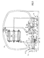
- la figure 1 illustre une vue arrière d'une citerne équipée d'un dispositif de rangement selon l'invention ;
- la figure 2 illustre une vue de détail en coupe transversale partielle du conduit du dispositif de rangement selon l'invention ;
- la figure 3 illustre une vue de côté d'une citerne équipée d'un dispositif de rangement selon l'invention ;
- la figure 4 illustre une vue de détail de dessus du côté d'une citerne équipée d'un dispositif de rangement selon l'invention, le tuyau étant en position complètement rangé ;
- la figure 5 illustre une vue de détail de dessus du côté d'une citerne équipée d'un dispositif de rangement selon l'invention, le tuyau étant en position complètement extrait ;
- la figure 6 illustre une vue de détail de dessus de l'arrière d'une citerne équipée d'un dispositif de rangement selon l'invention, le tuyau étant en position complètement rangé ;
- la figure 7 illustre une vue du face du système de retrait piloté ; et
- la figure 8 illustre une vue de côté du système de retrait piloté.
Claims (13)
- Dispositif (10) de rangement d'un tuyau (20) flexible associé à une citerne (30), et notamment une citerne de camion, semi-remorque ou remorque, une extrémité (21) dudit tuyau (20) étant reliée à ladite citerne (30), caractérisé en ce qu'il est constitué d'un conduit (40) longitudinal disposé le long de ladite citerne (30), ledit conduit (40) étant refermé afin d'empêcher l'accès audit tuyau lorsqu'il est rangé dans ledit conduit (40).
- Dispositif (10) de rangement selon la revendication 1, caractérisé en ce qu'il comporte un bâti constitué d'un fond (41) longitudinal, de parois latérales (42, 42'), éventuellement une paroi supérieure (43) longitudinale, ainsi que des parois transversales (44, 44') respectivement avant et arrière.
- Dispositif (10) de rangement selon la revendication 2, caractérisé en ce que ladite paroi transversale (44') arrière est formée par une trappe (51) d'un caisson arrière (50) disposé à l'arrière de ladite citerne (30).
- Dispositif (10) de rangement selon la revendication 2 ou la revendication 3, caractérisé en ce qu'au moins une paroi latérale (42, 42') est munie d'au moins une trappe latérale (45).
- Dispositif (10) de rangement selon la revendication 3 ou la revendication 4, caractérisé en ce que ladite ou lesdites trappe(s) latérale(s) (15) et/ou ladite trappe (51) est ou sont munie(s) d'un moyen de blocage.
- Dispositif (10) de rangement selon la revendication 5, caractérisé en ce que le moyen de blocage de ladite ou desdites trappe(s) latérale(s) (15) est constitué au moins par une tige (46) présentant des crochets de blocage (47), pour le blocage des trappes (45), ladite tige (46) étant mobile en rotation entre une position de fermeture dans laquelle lesdits crochets (47) empêchent l'ouverture des trappes (45) et une position d'ouverture dans laquelle lesdits crochets (47) autorisent l'ouverture des trappes (45).
- Dispositif (10) de rangement selon l'une quelconque des revendications 1 à 6, caractérisé en ce qu'il comporte un système de retrait piloté (60) d'une extrémité (22) dudit tuyau (20).
- Dispositif (10) de rangement selon la revendication 7, caractérisé en ce que ledit système de retrait piloté (60) comporte un galet d'entraínement (61) mis en contact avec l'extrémité supérieure de la surface extérieure (23) du tuyau (20) par l'intermédiaire d'un dispositif d'amené (62).
- Dispositif (10) de rangement selon la revendication 8, caractérisé en ce que ledit dispositif d'amené (62) est constitué d'au moins un vérin, et de préférence de deux vérins (65, 65') disposés de part et d'autre de l'axe (25) du tuyau (20) dans ledit système de retrait piloté (60), et d'un galet presseur (63) monté en libre rotation.
- Dispositif (10) de rangement selon l'une quelconque des revendications 1 à 9, caractérisé en ce qu'il comporte une brosse cylindrique (68) présentant un diamètre intérieur de brossage inférieur au diamètre extérieur (24) dudit tuyau (20).
- Dispositif (10) de rangement selon l'une quelconque des revendications 1 à 10, caractérisé en ce qu'il comporte un système de lavage (11) constitué d'au moins une rampe de distribution (12) s'étendant à l'intérieur dudit conduit (40) et d'une pluralité d'orifices de lavage (13).
- Citerne (30), et notamment citerne de camion, semi-remorque ou remorque, comportant un dispositif (1) selon l'une quelconque des revendications 1 à 11, et présentant un conduit (40) longitudinal disposé le long de ladite citerne (30), ledit conduit (40) étant refermé afin d'empêcher l'accès audit tuyau (20) lorsqu'il est rangé dans ledit conduit (40).
- Citerne (30) selon la revendication 12, caractérisée en ce que ledit conduit (40) est disposé sur un côté.
Applications Claiming Priority (2)
| Application Number | Priority Date | Filing Date | Title |
|---|---|---|---|
| FR0301680A FR2850961B1 (fr) | 2003-02-12 | 2003-02-12 | Dispositif de rangement pour tuyau flexible de citerne et citerne equipee dudit dispositif |
| FR0301680 | 2003-02-12 |
Publications (2)
| Publication Number | Publication Date |
|---|---|
| EP1447268A1 true EP1447268A1 (fr) | 2004-08-18 |
| EP1447268B1 EP1447268B1 (fr) | 2009-04-08 |
Family
ID=32669353
Family Applications (1)
| Application Number | Title | Priority Date | Filing Date |
|---|---|---|---|
| EP04290357A Expired - Lifetime EP1447268B1 (fr) | 2003-02-12 | 2004-02-11 | Dispositif de rangement pour tuyau flexible de citerne et citerne équipée dudit dispositif |
Country Status (7)
| Country | Link |
|---|---|
| EP (1) | EP1447268B1 (fr) |
| AT (1) | ATE427857T1 (fr) |
| DE (1) | DE602004020409D1 (fr) |
| ES (1) | ES2325075T3 (fr) |
| FR (1) | FR2850961B1 (fr) |
| PL (1) | PL365095A1 (fr) |
| RU (1) | RU2004103049A (fr) |
Citations (7)
| Publication number | Priority date | Publication date | Assignee | Title |
|---|---|---|---|---|
| US1351253A (en) * | 1920-05-03 | 1920-08-31 | Andrew A Kramer | Can-rack |
| US1978457A (en) * | 1931-10-26 | 1934-10-30 | Standard Steel Works | Hose carrier for truck tanks |
| US2087247A (en) * | 1934-04-12 | 1937-07-20 | Atlantic Refining Co | Hose housing for tank-carrying vehicles |
| US4135596A (en) * | 1977-11-25 | 1979-01-23 | Silba Glen R | Hose tray for liquid transporter |
| FR2592286A1 (fr) * | 1985-12-30 | 1987-07-03 | Wessel Werk Gmbh | Brosse pour nettoyer la surface de corps tubulaire |
| US5647084A (en) * | 1996-01-18 | 1997-07-15 | Still; Ed | Apparatus for cleaning exterior or hoses, pipes, etc. |
| DE29911592U1 (de) * | 1999-07-02 | 2000-11-16 | Toi Toi & Dixi Sanitärsysteme GmbH, 01809 Dohna | Schlauchkassette mit einer Einfahrvorrichtung für den Schlauch der Schlauchkassette |
Family Cites Families (2)
| Publication number | Priority date | Publication date | Assignee | Title |
|---|---|---|---|---|
| BE658483A (fr) * | ||||
| FR2791960B1 (fr) * | 1999-04-12 | 2001-06-29 | Guhur Ets | Citerne mobile equipee de tuyaux flexibles de remplissage et/ou de vidage |
-
2003
- 2003-02-12 FR FR0301680A patent/FR2850961B1/fr not_active Expired - Lifetime
-
2004
- 2004-02-04 RU RU2004103049/12A patent/RU2004103049A/ru not_active Application Discontinuation
- 2004-02-11 EP EP04290357A patent/EP1447268B1/fr not_active Expired - Lifetime
- 2004-02-11 AT AT04290357T patent/ATE427857T1/de not_active IP Right Cessation
- 2004-02-11 PL PL04365095A patent/PL365095A1/xx not_active IP Right Cessation
- 2004-02-11 DE DE602004020409T patent/DE602004020409D1/de not_active Expired - Lifetime
- 2004-02-11 ES ES04290357T patent/ES2325075T3/es not_active Expired - Lifetime
Patent Citations (7)
| Publication number | Priority date | Publication date | Assignee | Title |
|---|---|---|---|---|
| US1351253A (en) * | 1920-05-03 | 1920-08-31 | Andrew A Kramer | Can-rack |
| US1978457A (en) * | 1931-10-26 | 1934-10-30 | Standard Steel Works | Hose carrier for truck tanks |
| US2087247A (en) * | 1934-04-12 | 1937-07-20 | Atlantic Refining Co | Hose housing for tank-carrying vehicles |
| US4135596A (en) * | 1977-11-25 | 1979-01-23 | Silba Glen R | Hose tray for liquid transporter |
| FR2592286A1 (fr) * | 1985-12-30 | 1987-07-03 | Wessel Werk Gmbh | Brosse pour nettoyer la surface de corps tubulaire |
| US5647084A (en) * | 1996-01-18 | 1997-07-15 | Still; Ed | Apparatus for cleaning exterior or hoses, pipes, etc. |
| DE29911592U1 (de) * | 1999-07-02 | 2000-11-16 | Toi Toi & Dixi Sanitärsysteme GmbH, 01809 Dohna | Schlauchkassette mit einer Einfahrvorrichtung für den Schlauch der Schlauchkassette |
Also Published As
| Publication number | Publication date |
|---|---|
| FR2850961A1 (fr) | 2004-08-13 |
| FR2850961B1 (fr) | 2006-08-18 |
| EP1447268B1 (fr) | 2009-04-08 |
| ES2325075T3 (es) | 2009-08-25 |
| DE602004020409D1 (de) | 2009-05-20 |
| PL365095A1 (en) | 2004-08-23 |
| RU2004103049A (ru) | 2005-07-10 |
| ATE427857T1 (de) | 2009-04-15 |
Similar Documents
| Publication | Publication Date | Title |
|---|---|---|
| EP1941821A1 (fr) | Distributeur de rouleaux disposés côte à côte et muni d'une trappe coulissante inférieure | |
| EP2709931B1 (fr) | Conteneur d'ordures ménagerès ainsi que le procédé de désinfection ou de nettoyage d'un tel conteneur | |
| WO2017207939A1 (fr) | Container de collecte de dechets alimentaires | |
| FR2477432A1 (fr) | Dispositif d'essorage pour rouleau a peindre | |
| FR2925372A1 (fr) | Robot de nettoyage de l'interieur d'enceintes, notamment de l'interieur de camions frigorifiques. | |
| FR2475990A3 (fr) | Dispositif de nettoiement | |
| EP1447268B1 (fr) | Dispositif de rangement pour tuyau flexible de citerne et citerne équipée dudit dispositif | |
| EP1098827B1 (fr) | Benne pour la collecte et le transport d'une charge du type dechets menagers | |
| WO1994013367A1 (fr) | Dispositif pour le nettoyage des clubs de golf | |
| FR2942181A3 (fr) | Vehicule pourvu d'un bac de rangement d'un tendelet et procede de rangement et de remise en service du tendelet | |
| FR2978960A1 (fr) | Conteneur de collecte des dechets dote d'un systeme d'actionnement de trappes perfectionne | |
| FR2645399A1 (fr) | Dispositif de chargement et de dechargement de balles cylindriques de paille ou de fourrage | |
| FR2921053A1 (fr) | Chariot poubelle | |
| FR2492769A1 (fr) | Bidon a embout verseur | |
| FR2932465A1 (fr) | Dispositif de plate-forme d'accueil pour le vidage et le lavage des vehicules de nettoiement des chaussees | |
| FR2707264A1 (fr) | Dispositif distributeur de substance et système adapté pour le remplissage de celui-ci. | |
| EP3040294B1 (fr) | Système de stockage de déchets et de lixiviat | |
| FR2953439A1 (fr) | Dispositif permettant le decoffrage de bennes a beton | |
| FR2666725A1 (fr) | Porte de lavage d'une machine a baratter. | |
| FR2808863A1 (fr) | Dispositif de raccordement rapide et universel d'un tube mobile et d'un element tubulaire fixe | |
| EP2311758B1 (fr) | Conteneur d'apport volontaire de déchets et camion de lavage d'un tel conteneur | |
| FR2590241A1 (fr) | Installation de nettoyage de conteneurs, et vehicule equipe de ladite installation | |
| EP0486412A1 (fr) | Caisse à litière pour animaux domestiques | |
| FR2909363A3 (fr) | Dispositif pour le remplissage d'un receptacle et procede correspondant | |
| FR3028192A1 (fr) | Ensemble d'elements permettant l'extraction de dechets hors d'une machine de sterilisation de ces dechets, et permettant l'evacuation de ces dechets |
Legal Events
| Date | Code | Title | Description |
|---|---|---|---|
| PUAI | Public reference made under article 153(3) epc to a published international application that has entered the european phase |
Free format text: ORIGINAL CODE: 0009012 |
|
| AK | Designated contracting states |
Kind code of ref document: A1 Designated state(s): AT BE BG CH CY CZ DE DK EE ES FI FR GB GR HU IE IT LI LU MC NL PT RO SE SI SK TR |
|
| AX | Request for extension of the european patent |
Extension state: AL LT LV MK |
|
| 17P | Request for examination filed |
Effective date: 20041227 |
|
| AKX | Designation fees paid |
Designated state(s): AT BE BG CH CY CZ DE DK EE ES FI FR GB GR HU IE IT LI LU MC NL PT RO SE SI SK TR |
|
| 17Q | First examination report despatched |
Effective date: 20050413 |
|
| GRAP | Despatch of communication of intention to grant a patent |
Free format text: ORIGINAL CODE: EPIDOSNIGR1 |
|
| GRAS | Grant fee paid |
Free format text: ORIGINAL CODE: EPIDOSNIGR3 |
|
| GRAA | (expected) grant |
Free format text: ORIGINAL CODE: 0009210 |
|
| AK | Designated contracting states |
Kind code of ref document: B1 Designated state(s): AT BE BG CH CY CZ DE DK EE ES FI FR GB GR HU IE IT LI LU MC NL PT RO SE SI SK TR |
|
| REG | Reference to a national code |
Ref country code: GB Ref legal event code: FG4D Free format text: NOT ENGLISH |
|
| REG | Reference to a national code |
Ref country code: CH Ref legal event code: EP |
|
| REG | Reference to a national code |
Ref country code: IE Ref legal event code: FG4D |
|
| REF | Corresponds to: |
Ref document number: 602004020409 Country of ref document: DE Date of ref document: 20090520 Kind code of ref document: P |
|
| PG25 | Lapsed in a contracting state [announced via postgrant information from national office to epo] |
Ref country code: SI Free format text: LAPSE BECAUSE OF FAILURE TO SUBMIT A TRANSLATION OF THE DESCRIPTION OR TO PAY THE FEE WITHIN THE PRESCRIBED TIME-LIMIT Effective date: 20090408 |
|
| REG | Reference to a national code |
Ref country code: ES Ref legal event code: FG2A Ref document number: 2325075 Country of ref document: ES Kind code of ref document: T3 |
|
| REG | Reference to a national code |
Ref country code: IE Ref legal event code: FD4D |
|
| PG25 | Lapsed in a contracting state [announced via postgrant information from national office to epo] |
Ref country code: AT Free format text: LAPSE BECAUSE OF FAILURE TO SUBMIT A TRANSLATION OF THE DESCRIPTION OR TO PAY THE FEE WITHIN THE PRESCRIBED TIME-LIMIT Effective date: 20090408 Ref country code: PT Free format text: LAPSE BECAUSE OF FAILURE TO SUBMIT A TRANSLATION OF THE DESCRIPTION OR TO PAY THE FEE WITHIN THE PRESCRIBED TIME-LIMIT Effective date: 20090908 Ref country code: FI Free format text: LAPSE BECAUSE OF FAILURE TO SUBMIT A TRANSLATION OF THE DESCRIPTION OR TO PAY THE FEE WITHIN THE PRESCRIBED TIME-LIMIT Effective date: 20090408 |
|
| PG25 | Lapsed in a contracting state [announced via postgrant information from national office to epo] |
Ref country code: SE Free format text: LAPSE BECAUSE OF FAILURE TO SUBMIT A TRANSLATION OF THE DESCRIPTION OR TO PAY THE FEE WITHIN THE PRESCRIBED TIME-LIMIT Effective date: 20090708 |
|
| PG25 | Lapsed in a contracting state [announced via postgrant information from national office to epo] |
Ref country code: DK Free format text: LAPSE BECAUSE OF FAILURE TO SUBMIT A TRANSLATION OF THE DESCRIPTION OR TO PAY THE FEE WITHIN THE PRESCRIBED TIME-LIMIT Effective date: 20090408 Ref country code: CZ Free format text: LAPSE BECAUSE OF FAILURE TO SUBMIT A TRANSLATION OF THE DESCRIPTION OR TO PAY THE FEE WITHIN THE PRESCRIBED TIME-LIMIT Effective date: 20090408 Ref country code: EE Free format text: LAPSE BECAUSE OF FAILURE TO SUBMIT A TRANSLATION OF THE DESCRIPTION OR TO PAY THE FEE WITHIN THE PRESCRIBED TIME-LIMIT Effective date: 20090408 Ref country code: IE Free format text: LAPSE BECAUSE OF FAILURE TO SUBMIT A TRANSLATION OF THE DESCRIPTION OR TO PAY THE FEE WITHIN THE PRESCRIBED TIME-LIMIT Effective date: 20090408 Ref country code: RO Free format text: LAPSE BECAUSE OF FAILURE TO SUBMIT A TRANSLATION OF THE DESCRIPTION OR TO PAY THE FEE WITHIN THE PRESCRIBED TIME-LIMIT Effective date: 20090408 |
|
| PLBE | No opposition filed within time limit |
Free format text: ORIGINAL CODE: 0009261 |
|
| STAA | Information on the status of an ep patent application or granted ep patent |
Free format text: STATUS: NO OPPOSITION FILED WITHIN TIME LIMIT |
|
| PG25 | Lapsed in a contracting state [announced via postgrant information from national office to epo] |
Ref country code: SK Free format text: LAPSE BECAUSE OF FAILURE TO SUBMIT A TRANSLATION OF THE DESCRIPTION OR TO PAY THE FEE WITHIN THE PRESCRIBED TIME-LIMIT Effective date: 20090408 |
|
| 26N | No opposition filed |
Effective date: 20100111 |
|
| PG25 | Lapsed in a contracting state [announced via postgrant information from national office to epo] |
Ref country code: BG Free format text: LAPSE BECAUSE OF FAILURE TO SUBMIT A TRANSLATION OF THE DESCRIPTION OR TO PAY THE FEE WITHIN THE PRESCRIBED TIME-LIMIT Effective date: 20090708 |
|
| REG | Reference to a national code |
Ref country code: CH Ref legal event code: PL |
|
| PG25 | Lapsed in a contracting state [announced via postgrant information from national office to epo] |
Ref country code: CH Free format text: LAPSE BECAUSE OF NON-PAYMENT OF DUE FEES Effective date: 20100228 Ref country code: GR Free format text: LAPSE BECAUSE OF FAILURE TO SUBMIT A TRANSLATION OF THE DESCRIPTION OR TO PAY THE FEE WITHIN THE PRESCRIBED TIME-LIMIT Effective date: 20090709 Ref country code: LI Free format text: LAPSE BECAUSE OF NON-PAYMENT OF DUE FEES Effective date: 20100228 Ref country code: MC Free format text: LAPSE BECAUSE OF NON-PAYMENT OF DUE FEES Effective date: 20100301 |
|
| PG25 | Lapsed in a contracting state [announced via postgrant information from national office to epo] |
Ref country code: IT Free format text: LAPSE BECAUSE OF NON-PAYMENT OF DUE FEES Effective date: 20100211 |
|
| PGRI | Patent reinstated in contracting state [announced from national office to epo] |
Ref country code: IT Effective date: 20110616 |
|
| PGFP | Annual fee paid to national office [announced via postgrant information from national office to epo] |
Ref country code: TR Payment date: 20120111 Year of fee payment: 9 |
|
| PGFP | Annual fee paid to national office [announced via postgrant information from national office to epo] |
Ref country code: IT Payment date: 20120213 Year of fee payment: 9 Ref country code: GB Payment date: 20120208 Year of fee payment: 9 |
|
| PG25 | Lapsed in a contracting state [announced via postgrant information from national office to epo] |
Ref country code: CY Free format text: LAPSE BECAUSE OF FAILURE TO SUBMIT A TRANSLATION OF THE DESCRIPTION OR TO PAY THE FEE WITHIN THE PRESCRIBED TIME-LIMIT Effective date: 20090408 |
|
| PG25 | Lapsed in a contracting state [announced via postgrant information from national office to epo] |
Ref country code: HU Free format text: LAPSE BECAUSE OF FAILURE TO SUBMIT A TRANSLATION OF THE DESCRIPTION OR TO PAY THE FEE WITHIN THE PRESCRIBED TIME-LIMIT Effective date: 20091009 Ref country code: LU Free format text: LAPSE BECAUSE OF NON-PAYMENT OF DUE FEES Effective date: 20100211 |
|
| PGFP | Annual fee paid to national office [announced via postgrant information from national office to epo] |
Ref country code: ES Payment date: 20120307 Year of fee payment: 9 |
|
| GBPC | Gb: european patent ceased through non-payment of renewal fee |
Effective date: 20130211 |
|
| PG25 | Lapsed in a contracting state [announced via postgrant information from national office to epo] |
Ref country code: IT Free format text: LAPSE BECAUSE OF NON-PAYMENT OF DUE FEES Effective date: 20130211 |
|
| PG25 | Lapsed in a contracting state [announced via postgrant information from national office to epo] |
Ref country code: GB Free format text: LAPSE BECAUSE OF NON-PAYMENT OF DUE FEES Effective date: 20130211 |
|
| REG | Reference to a national code |
Ref country code: ES Ref legal event code: FD2A Effective date: 20140408 |
|
| PG25 | Lapsed in a contracting state [announced via postgrant information from national office to epo] |
Ref country code: ES Free format text: LAPSE BECAUSE OF NON-PAYMENT OF DUE FEES Effective date: 20130212 |
|
| PG25 | Lapsed in a contracting state [announced via postgrant information from national office to epo] |
Ref country code: TR Free format text: LAPSE BECAUSE OF NON-PAYMENT OF DUE FEES Effective date: 20130211 |
|
| REG | Reference to a national code |
Ref country code: FR Ref legal event code: PLFP Year of fee payment: 13 |
|
| REG | Reference to a national code |
Ref country code: FR Ref legal event code: PLFP Year of fee payment: 14 |
|
| REG | Reference to a national code |
Ref country code: FR Ref legal event code: PLFP Year of fee payment: 15 |
|
| PGFP | Annual fee paid to national office [announced via postgrant information from national office to epo] |
Ref country code: NL Payment date: 20230220 Year of fee payment: 20 |
|
| PGFP | Annual fee paid to national office [announced via postgrant information from national office to epo] |
Ref country code: FR Payment date: 20230217 Year of fee payment: 20 |
|
| PGFP | Annual fee paid to national office [announced via postgrant information from national office to epo] |
Ref country code: DE Payment date: 20230216 Year of fee payment: 20 Ref country code: BE Payment date: 20230220 Year of fee payment: 20 |
|
| REG | Reference to a national code |
Ref country code: DE Ref legal event code: R071 Ref document number: 602004020409 Country of ref document: DE |
|
| REG | Reference to a national code |
Ref country code: NL Ref legal event code: MK Effective date: 20240210 |
|
| REG | Reference to a national code |
Ref country code: BE Ref legal event code: MK Effective date: 20240211 |