EP1447242A1 - Pressure sensor, transmitter, and tire condition monitoring apparatus - Google Patents
Pressure sensor, transmitter, and tire condition monitoring apparatus Download PDFInfo
- Publication number
- EP1447242A1 EP1447242A1 EP03028523A EP03028523A EP1447242A1 EP 1447242 A1 EP1447242 A1 EP 1447242A1 EP 03028523 A EP03028523 A EP 03028523A EP 03028523 A EP03028523 A EP 03028523A EP 1447242 A1 EP1447242 A1 EP 1447242A1
- Authority
- EP
- European Patent Office
- Prior art keywords
- transmitter
- pressure sensor
- metallic material
- tire
- power supply
- Prior art date
- Legal status (The legal status is an assumption and is not a legal conclusion. Google has not performed a legal analysis and makes no representation as to the accuracy of the status listed.)
- Withdrawn
Links
- 238000012544 monitoring process Methods 0.000 title claims abstract description 10
- 239000007769 metal material Substances 0.000 claims abstract description 38
- 230000005611 electricity Effects 0.000 claims abstract description 7
- 238000000034 method Methods 0.000 claims abstract description 5
- 239000004020 conductor Substances 0.000 claims description 7
- WABPQHHGFIMREM-UHFFFAOYSA-N lead(0) Chemical compound [Pb] WABPQHHGFIMREM-UHFFFAOYSA-N 0.000 claims description 6
- 239000000919 ceramic Substances 0.000 claims description 2
- 239000002184 metal Substances 0.000 claims 1
- 238000007747 plating Methods 0.000 claims 1
- 230000003213 activating effect Effects 0.000 abstract description 2
- 230000005540 biological transmission Effects 0.000 description 15
- 239000000758 substrate Substances 0.000 description 8
- 230000006870 function Effects 0.000 description 5
- 230000005672 electromagnetic field Effects 0.000 description 3
- 238000010586 diagram Methods 0.000 description 2
- 230000000694 effects Effects 0.000 description 2
- XAGFODPZIPBFFR-UHFFFAOYSA-N aluminium Chemical compound [Al] XAGFODPZIPBFFR-UHFFFAOYSA-N 0.000 description 1
- 229910052782 aluminium Inorganic materials 0.000 description 1
- 239000011324 bead Substances 0.000 description 1
- 230000008021 deposition Effects 0.000 description 1
- 238000005259 measurement Methods 0.000 description 1
- WFKWXMTUELFFGS-UHFFFAOYSA-N tungsten Chemical compound [W] WFKWXMTUELFFGS-UHFFFAOYSA-N 0.000 description 1
- 229910052721 tungsten Inorganic materials 0.000 description 1
- 239000010937 tungsten Substances 0.000 description 1
Images

Classifications
-
- B—PERFORMING OPERATIONS; TRANSPORTING
- B60—VEHICLES IN GENERAL
- B60C—VEHICLE TYRES; TYRE INFLATION; TYRE CHANGING; CONNECTING VALVES TO INFLATABLE ELASTIC BODIES IN GENERAL; DEVICES OR ARRANGEMENTS RELATED TO TYRES
- B60C23/00—Devices for measuring, signalling, controlling, or distributing tyre pressure or temperature, specially adapted for mounting on vehicles; Arrangement of tyre inflating devices on vehicles, e.g. of pumps or of tanks; Tyre cooling arrangements
- B60C23/02—Signalling devices actuated by tyre pressure
- B60C23/04—Signalling devices actuated by tyre pressure mounted on the wheel or tyre
- B60C23/0491—Constructional details of means for attaching the control device
- B60C23/0494—Valve stem attachments positioned inside the tyre chamber
-
- B—PERFORMING OPERATIONS; TRANSPORTING
- B60—VEHICLES IN GENERAL
- B60C—VEHICLE TYRES; TYRE INFLATION; TYRE CHANGING; CONNECTING VALVES TO INFLATABLE ELASTIC BODIES IN GENERAL; DEVICES OR ARRANGEMENTS RELATED TO TYRES
- B60C23/00—Devices for measuring, signalling, controlling, or distributing tyre pressure or temperature, specially adapted for mounting on vehicles; Arrangement of tyre inflating devices on vehicles, e.g. of pumps or of tanks; Tyre cooling arrangements
- B60C23/02—Signalling devices actuated by tyre pressure
- B60C23/04—Signalling devices actuated by tyre pressure mounted on the wheel or tyre
- B60C23/0408—Signalling devices actuated by tyre pressure mounted on the wheel or tyre transmitting the signals by non-mechanical means from the wheel or tyre to a vehicle body mounted receiver
-
- G—PHYSICS
- G01—MEASURING; TESTING
- G01L—MEASURING FORCE, STRESS, TORQUE, WORK, MECHANICAL POWER, MECHANICAL EFFICIENCY, OR FLUID PRESSURE
- G01L9/00—Measuring steady of quasi-steady pressure of fluid or fluent solid material by electric or magnetic pressure-sensitive elements; Transmitting or indicating the displacement of mechanical pressure-sensitive elements, used to measure the steady or quasi-steady pressure of a fluid or fluent solid material, by electric or magnetic means
- G01L9/0041—Transmitting or indicating the displacement of flexible diaphragms
- G01L9/0072—Transmitting or indicating the displacement of flexible diaphragms using variations in capacitance
- G01L9/0075—Transmitting or indicating the displacement of flexible diaphragms using variations in capacitance using a ceramic diaphragm, e.g. alumina, fused quartz, glass
Definitions
- the present invention relates to a pressure sensor, a transmitter that has the pressure sensor, and a tire condition monitoring apparatus that has the transmitter.
- Japanese Laid-Open Patent Publication No. 8-94468 discloses a structure of a pressure sensor unit, in which a pressure sensor is adhered to a lead terminal that also functions as a shielding member.
- the pressure sensor is three-dimensionally covered by the lead terminal. This structure prevents the pressure sensor from being affected by outside electromagnetic fields and thus allows the pressure sensor to accurately measure a pressure.
- the pressure sensor is three-dimensionally covered with the lead terminal, which also functions as a shielding member. This increases the size of the pressure sensor unit. In other words, the structure of the publication cannot reduce a size of a pressure sensor unit that includes a shielding member.
- the present invention also relates to a transmitter having such a pressure sensor and a tire condition monitoring apparatus having such a transmitter.
- a pressure sensor having a diaphragm and metallic material is provided.
- the diaphragm is exposed to gas.
- the metallic material covers the diaphragm.
- a predetermined voltage can be applied to the metallic material.
- the present invention also provides a transmitter having a pressure sensor that has a diaphragm exposed to gas.
- the transmitter transmits pressure data detected'by the pressure sensor.
- the transmitter includes a power supply circuit, metallic material, and a connecting member.
- the power supply circuit supplies electricity to the transmitter.
- the metallic material covers the diaphragm.
- the connecting member connects the power supply circuit with the metallic material such that the potential of the metallic material is the same as the potential of the power supply circuit.
- the present invention provides a tire condition monitoring apparatus having a pressure sensor that measures air pressure in a tire of a vehicle, a transmitter that transmits pressure data measured by the pressure sensor, and a receiver that receives and processes data transmitted by the transmitter.
- the pressure sensor includes a diaphragm and metallic material. The diaphragm is exposed to air in the tire. The metallic material covers the diaphragm.
- the transmitter includes a power supply circuit and a connecting member. The power supply circuit supplies electricity for activating the transmitter.
- the connecting member connects the power supply circuit with the metallic material such that the potential of the metallic material is the same as the potential of the power supply circuit.
- the tire condition monitoring apparatus 1 includes four transmitters 30 and a receiver 40.
- Each transmitter 30 is located in one of the tires 20 of a vehicle 10.
- the receiver 40 is located on a body frame 11 of the vehicle 10.
- Each transmitter 30 is located in the corresponding tire 20 and is fixed, for example, to a wheel 21 of the tire 20. Each transmitter 30 measures the condition of the corresponding tire 20, that is, the pressure of the tire 20. The transmitter 30 then wirelessly transmits data containing air pressure data.
- the receiver 40 is located at a predetermined position on the body frame 11 and is activated by electricity of a battery (not shown) of the vehicle 10.
- the receiver 40 includes a single reception antenna 41.
- the reception antenna 41 is connected to the receiver 40 with a cable 42.
- the receiver 40 receives data transmitted by the transmitters 30 through the reception antenna 41.
- a display 50 is located in the view of the driver of the vehicle 10, for example, in the passenger compartment.
- the display 50 is connected to the receiver 40 with a cable 43.
- each transmitter 30 is accommodated in a casing 70, that is located below a valve stem 60. Air is injected into the tire 20 through the valve stem 60.
- the casing 70 is substantially formed into a rectangular box.
- the casing 70 accommodates a substantially rectangular substrate 80.
- Electronic elements such as transmission controller 31, a pressure sensor 32, a transmission circuit 33, a transmission antenna 34, and a battery 35 are mounted on the substrate 80.
- the substrate 80 is fixed to bosses 71 that are integrally formed with the casing 70.
- the casing 70 has a through hole (not shown) to permit the pressure sensor 32 to measure the air pressure in the tire 20.
- the casing 70 has an opening 72, which is closed with a lid (not shown) for protecting the electronic elements.
- each transmitter 30 includes a transmission controller 31, which is a microcomputer.
- the transmission controller 31 includes, for example, a central processing unit (CPU), a read only memory (ROM), and a random access memory (RAM).
- a unique ID code is registered in an internal memory, for example, the ROM, of the transmission controller 31. The ID code is used to distinguish the associated transmitter 30 from the other three transmitters 30.
- the pressure sensor 32 measures the air pressure in the interior of the associated tire 20 and provides the transmission controller 31 with pressure data, which is obtained from the measurement.
- the transmission controller 31 sends data containing the air pressure data and the registered ID code to a transmission circuit 33.
- the transmission circuit 33 encodes and modulates the data sent from the transmission controller 31.
- the transmission circuit 33 then wirelessly sends the data through a transmission antenna 34.
- the transmitter 30 is provided with a battery 35. The transmitter 30 is driven by electricity of the battery 35.
- the pressure senor 32 is made of ceramic, and has an upper base 100 and a lower base 200.
- a metallic material film 101 is formed on the outer surface of the upper base 100.
- a frustoconical recess 102 is formed in a central portion of the upper base 100.
- a diaphragm 103 is formed in an central upper portion of the upper base 100.
- a first inner electrode 104 is formed on the lower surface of the diaphragm 103.
- a second inner electrode 201 is formed in a center of the upper surface of the lower base 200.
- the metallic material film 101, the first inner electrode 104, and the second inner electrode 201 are formed by aluminum deposition.
- the upper base 100 and the lower base 200 are hermetically attached to each other such that the first inner electrode 104 and the second inner electrode 201 face each other.
- a hermetic space 105 is defined between the first inner electrode 104 and the second inner electrode 201.
- the hermetic space 105 is filled with gas having a predetermined pressure.
- the metallic material film 101 which covers the diaphragm 103, is exposed to the air inside the tire 20 through the through hole (not shown) formed in the casing 70. In other words, the metallic material film 101 is exposed to air, which is a measured gas. Therefore, when the air pressure in the tire 20 changes, the difference between the air pressure in the tire 20 and the pressure of the gas filling the hermetic space 105 is changed. Accordingly, the diaphragm 103 is flexed. Then, the distance between the first inner electrode 104 and the second inner electrode 201, which changes a capacitance between the first inner electrode 104 and the second inner electrode 201, accordingly. Therefore, the air pressure in the tire 20 is measured based on the capacitance between the first inner electrode 104 and the second inner electrode 201. That is, the pressure sensor 32 is a capacitance type pressure sensor.
- the metallic material film 101 on the upper base 100 is connected to the battery 35 with a lead wire 300 and traces of the wiring pattern on the substrate 80.
- the lead wire 300 and the traces function as connecting means.
- the metallic material film 101 is connected to a power supply potential Vdd (+3V) or a ground potential GND (0V) of the battery 35.
- Vdd (+3V) or a ground potential GND (0V) of the battery 35 As a result, the metallic material film 101 on the upper base 100 is maintained to the same potential as the power supply potential Vdd (+3V) or the ground potential GND (0V) of the battery 35.
- the ground potential GND (0V) of the battery 35 is connected to a ground potential GND of the transmission circuit 33.
- the battery 35 and the transmission circuit 33 function as a power supply circuit that supplies electricity to the transmitter 30.
- This embodiment has the following advantages.
- the metallic material film 101 on the upper base 100 may be directly connected to the power supply potential Vdd (+3V) or the ground potential GND (0V) of the battery 35 with the lead wire 300, without using the traces on the substrate 80.
- the metallic material film 101 on the upper base 100 may be connected to the power supply potential Vdd (+3V) or the ground potential GND (0V) of the battery 35 with the traces on the substrate 80 and a tungsten plated through hole 400.
- a conductor 500 having bent ends may be provided on a lid 73 of the casing 70.
- the metallic material film 101 on the upper base 100 may be connected to the battery 35 (for example, a positive terminal) with the conductor 500 when the opening 72 is closed with the lid 73.
- the shielding effect is obtained only by closing the opening 72 of the casing 70 with the lid 73 with the conductor 500.
- a step for attaching the conductor 500 to the lid 73 is added. In other words, no complicated step is added to the procedure for obtaining the shielding effect.
- the transmitter 30 is easily assembled with the casing 70.
- the metallic material film 101 is formed on the entire upper surface of the upper base 100.
- the metallic material film 101 may be formed on a part of the upper surface of the upper base 100 to cover the diaphragm 103. That is, the metallic material film 101 may be formed only on a center portion of the upper surface of the upper base 100.
Landscapes
- Engineering & Computer Science (AREA)
- Mechanical Engineering (AREA)
- Chemical & Material Sciences (AREA)
- Ceramic Engineering (AREA)
- Physics & Mathematics (AREA)
- General Physics & Mathematics (AREA)
- Measuring Fluid Pressure (AREA)
- Tires In General (AREA)
Abstract
Description
- The present invention relates to a pressure sensor, a transmitter that has the pressure sensor, and a tire condition monitoring apparatus that has the transmitter.
- For example, Japanese Laid-Open Patent Publication No. 8-94468 discloses a structure of a pressure sensor unit, in which a pressure sensor is adhered to a lead terminal that also functions as a shielding member. The pressure sensor is three-dimensionally covered by the lead terminal. This structure prevents the pressure sensor from being affected by outside electromagnetic fields and thus allows the pressure sensor to accurately measure a pressure.
- However, the pressure sensor is three-dimensionally covered with the lead terminal, which also functions as a shielding member. This increases the size of the pressure sensor unit. In other words, the structure of the publication cannot reduce a size of a pressure sensor unit that includes a shielding member.
- Accordingly, it is an objective of the present invention to provide a compact pressure sensor that accurately measures a pressure. The present invention also relates to a transmitter having such a pressure sensor and a tire condition monitoring apparatus having such a transmitter.
- To achieve the foregoing and other objectives and in accordance with the purpose of the present invention, a pressure sensor having a diaphragm and metallic material is provided. The diaphragm is exposed to gas. The metallic material covers the diaphragm. A predetermined voltage can be applied to the metallic material.
- The present invention also provides a transmitter having a pressure sensor that has a diaphragm exposed to gas. The transmitter transmits pressure data detected'by the pressure sensor. The transmitter includes a power supply circuit, metallic material, and a connecting member. The power supply circuit supplies electricity to the transmitter. The metallic material covers the diaphragm. The connecting member connects the power supply circuit with the metallic material such that the potential of the metallic material is the same as the potential of the power supply circuit.
- Further, the present invention provides a tire condition monitoring apparatus having a pressure sensor that measures air pressure in a tire of a vehicle, a transmitter that transmits pressure data measured by the pressure sensor, and a receiver that receives and processes data transmitted by the transmitter. The pressure sensor includes a diaphragm and metallic material. The diaphragm is exposed to air in the tire. The metallic material covers the diaphragm. The transmitter includes a power supply circuit and a connecting member. The power supply circuit supplies electricity for activating the transmitter. The connecting member connects the power supply circuit with the metallic material such that the potential of the metallic material is the same as the potential of the power supply circuit.
- Other aspects and advantages of the invention will become apparent from the following description, taken in conjunction with the accompanying drawings, illustrating by-way of example the principles of the invention.
- The invention, together with objects and advantages thereof, may best be understood by reference to the following description of the presently preferred embodiments together with the accompanying drawings in which:
- Fig. 1 is a block diagram showing a tire condition monitoring apparatus according to one embodiment of the present invention;
- Fig. 2 is a diagrammatic view showing the structure of one of the transmitters shown in Fig. 1;
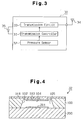
- Fig. 3 is a block diagram showing one of the transmitters shown in Fig. 1;
- Fig. 4 is a schematic cross-sectional view showing the pressure sensor shown in Fig. 3;
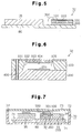
- Fig. 5 is a partially cross-sectional view showing the transmitter shown in Fig. 3;
- Fig. 6 is a schematic cross-sectional view showing a pressure sensor according to another embodiment; and
- Fig. 7 is a cross-sectional view showing a casing for accommodating a transmitter according to another embodiment.
-
- A pressure sensor, transmitters, and a tire condition monitoring apparatus according to the present invention will now be described with reference to the drawings.
- As shown in Fig. 1, the tire condition monitoring apparatus 1 includes four
transmitters 30 and areceiver 40. Eachtransmitter 30 is located in one of thetires 20 of avehicle 10. Thereceiver 40 is located on abody frame 11 of thevehicle 10. - Each
transmitter 30 is located in thecorresponding tire 20 and is fixed, for example, to awheel 21 of thetire 20. Eachtransmitter 30 measures the condition of thecorresponding tire 20, that is, the pressure of thetire 20. Thetransmitter 30 then wirelessly transmits data containing air pressure data. - The
receiver 40 is located at a predetermined position on thebody frame 11 and is activated by electricity of a battery (not shown) of thevehicle 10. Thereceiver 40 includes asingle reception antenna 41. Thereception antenna 41 is connected to thereceiver 40 with acable 42. Thereceiver 40 receives data transmitted by thetransmitters 30 through thereception antenna 41. - A
display 50 is located in the view of the driver of thevehicle 10, for example, in the passenger compartment. Thedisplay 50 is connected to thereceiver 40 with acable 43. - As shown in Fig. 2, each
transmitter 30 is accommodated in acasing 70, that is located below avalve stem 60. Air is injected into thetire 20 through thevalve stem 60. Thecasing 70 is substantially formed into a rectangular box. Thecasing 70 accommodates a substantiallyrectangular substrate 80. Electronic elements such astransmission controller 31, apressure sensor 32, atransmission circuit 33, atransmission antenna 34, and abattery 35 are mounted on thesubstrate 80. Thesubstrate 80 is fixed tobosses 71 that are integrally formed with thecasing 70. Thecasing 70 has a through hole (not shown) to permit thepressure sensor 32 to measure the air pressure in thetire 20. Thecasing 70 has an opening 72, which is closed with a lid (not shown) for protecting the electronic elements. - As shown in Fig. 3, each
transmitter 30 includes atransmission controller 31, which is a microcomputer. Thetransmission controller 31 includes, for example, a central processing unit (CPU), a read only memory (ROM), and a random access memory (RAM). A unique ID code is registered in an internal memory, for example, the ROM, of thetransmission controller 31. The ID code is used to distinguish the associatedtransmitter 30 from the other threetransmitters 30. - The
pressure sensor 32 measures the air pressure in the interior of the associatedtire 20 and provides thetransmission controller 31 with pressure data, which is obtained from the measurement. Thetransmission controller 31 sends data containing the air pressure data and the registered ID code to atransmission circuit 33. Thetransmission circuit 33 encodes and modulates the data sent from thetransmission controller 31. Thetransmission circuit 33 then wirelessly sends the data through atransmission antenna 34. Thetransmitter 30 is provided with abattery 35. Thetransmitter 30 is driven by electricity of thebattery 35. - As shown in Fig. 4, the
pressure senor 32 is made of ceramic, and has anupper base 100 and alower base 200. Ametallic material film 101 is formed on the outer surface of theupper base 100. Afrustoconical recess 102 is formed in a central portion of theupper base 100. As a result, adiaphragm 103 is formed in an central upper portion of theupper base 100. A firstinner electrode 104 is formed on the lower surface of thediaphragm 103. - A second
inner electrode 201 is formed in a center of the upper surface of thelower base 200. Themetallic material film 101, the firstinner electrode 104, and the secondinner electrode 201 are formed by aluminum deposition. Theupper base 100 and thelower base 200 are hermetically attached to each other such that the firstinner electrode 104 and the secondinner electrode 201 face each other. As a result, ahermetic space 105 is defined between the firstinner electrode 104 and the secondinner electrode 201. Thehermetic space 105 is filled with gas having a predetermined pressure. - The
metallic material film 101, which covers thediaphragm 103, is exposed to the air inside thetire 20 through the through hole (not shown) formed in thecasing 70. In other words, themetallic material film 101 is exposed to air, which is a measured gas. Therefore, when the air pressure in thetire 20 changes, the difference between the air pressure in thetire 20 and the pressure of the gas filling thehermetic space 105 is changed. Accordingly, thediaphragm 103 is flexed. Then, the distance between the firstinner electrode 104 and the secondinner electrode 201, which changes a capacitance between the firstinner electrode 104 and the secondinner electrode 201, accordingly. Therefore, the air pressure in thetire 20 is measured based on the capacitance between the firstinner electrode 104 and the secondinner electrode 201. That is, thepressure sensor 32 is a capacitance type pressure sensor. - As shown in Fig. 5, the
metallic material film 101 on theupper base 100 is connected to thebattery 35 with alead wire 300 and traces of the wiring pattern on thesubstrate 80. Thelead wire 300 and the traces function as connecting means. Specifically, themetallic material film 101 is connected to a power supply potential Vdd (+3V) or a ground potential GND (0V) of thebattery 35. As a result, themetallic material film 101 on theupper base 100 is maintained to the same potential as the power supply potential Vdd (+3V) or the ground potential GND (0V) of thebattery 35. The ground potential GND (0V) of thebattery 35 is connected to a ground potential GND of thetransmission circuit 33. Thebattery 35 and thetransmission circuit 33 function as a power supply circuit that supplies electricity to thetransmitter 30. - This embodiment has the following advantages.
- (1) The
metallic material film 101 is formed on the outer surface of theupper base 100 to cover thediaphragm 103. Themetallic material film 101 on theupper base 100 is connected to the power supply potential Vdd (+3V) or the ground potential GND (0V) of thebattery 35 with thelead wire 300 and the traces on thesubstrate 80. Accordingly, themetallic material film 101 on theupper base 100 is maintained to the same potential as the potential of thebattery 35. As a result, the firstinner electrode 104 and the secondinner electrode 201 of thepressure sensor 32 are shielded by themetallic material film 101. This structure prevents thepressure sensor 32 from being affected by outside electromagnetic fields and thus allows thepressure sensor 32 to accurately measure the air pressure in thetire 20. Unlike the structure disclosed in Japanese Laid-Open Patent Publication No. 8-94468, where the pressure sensor is three-dimensionally covered with a lead terminal that also functions as a shielding member, themetallic material film 101 on theupper base 100 is connected to the ground potential GND on thesubstrate 80 with thelead wire 300. Therefore, the size of thepressure sensor 32 is reduced. - (2) Since the size of the
pressure sensor 32 is reduced, the size of thetransmitter 30 is reduced. Therefore, when attaching thetire 20 to thewheel 21, the bead of thetire 20 is prevented from contacting thecasing 70, which accommodates thetransmitter 30. Therefore, when attaching thetire 20, thecasing 70 and thetransmitter 30 are not damaged. - (3) The
pressure sensor 32 is scarcely affected by outside electromagnetic fields. This permits thepressure sensor 32 to accurately measure even small changes in the air pressure in thetire 20. Therefore, thetransmitter 30 wirelessly transmits accurate air pressure data to thereceiver 40. - (4) The
receiver 40 receives data through thereception antenna 41 and, based on the received data, causes thedisplay 50 to display air pressure data. This informs a driver of thevehicle 10 of the accurate air pressure data. In other words, the present invention provides the tire condition monitoring apparatus 1, which accurately measures the air pressure in thetire 20. -
- It should be apparent to those skilled in the art that the present invention may be embodied in many other specific forms without departing from the spirit or scope of the invention. Particularly, it should be understood that the invention may be embodied in the following forms.
- The
metallic material film 101 on theupper base 100 may be directly connected to the power supply potential Vdd (+3V) or the ground potential GND (0V) of thebattery 35 with thelead wire 300, without using the traces on thesubstrate 80. - As shown in Fig. 6, the
metallic material film 101 on theupper base 100 may be connected to the power supply potential Vdd (+3V) or the ground potential GND (0V) of thebattery 35 with the traces on thesubstrate 80 and a tungsten plated throughhole 400. - As shown in Fig. 7, a
conductor 500 having bent ends may be provided on alid 73 of thecasing 70. Themetallic material film 101 on theupper base 100 may be connected to the battery 35 (for example, a positive terminal) with theconductor 500 when theopening 72 is closed with thelid 73. In this case, the shielding effect is obtained only by closing theopening 72 of thecasing 70 with thelid 73 with theconductor 500. Compared to conventional assembly procedure, only a step for attaching theconductor 500 to thelid 73 is added. In other words, no complicated step is added to the procedure for obtaining the shielding effect. Thus, with the structure of thelid 73 having theconductor 500, thetransmitter 30 is easily assembled with thecasing 70. - In the illustrated embodiment, the
metallic material film 101 is formed on the entire upper surface of theupper base 100. However, themetallic material film 101 may be formed on a part of the upper surface of theupper base 100 to cover thediaphragm 103. That is, themetallic material film 101 may be formed only on a center portion of the upper surface of theupper base 100. - Therefore, the present examples and embodiments are to be considered as illustrative and not restrictive and the invention is not to be limited to the details given herein, but may be modified within the scope and equivalence of the appended claims.
Claims (7)
- A pressure sensor having a diaphragm (103) exposed to gas, characterized in that
the diaphragm (103) is covered with metallic material (101), wherein a predetermined voltage can be applied to the metallic material. - A transmitter comprising a pressure sensor that has a diaphragm (103) exposed to gas, wherein the transmitter transmits pressure data detected by the pressure sensor, the transmitter being characterized by:a power supply circuit (33, 35) for supplying electricity to the transmitter;metallic material (101) covering the diaphragm; andconnecting means, wherein the connecting means connects the power supply circuit (33, 35) with the metallic material (101) such that the potential of the metallic material (101) is the same as the potential of the power supply circuit (33, 35).
- The transmitter according to claim 2, characterized in that the connecting means is a lead wire (300).
- The transmitter according to claim 2, characterized in that the diaphragm (103) is formed on a ceramic base (100), wherein the connecting means is metal plating on an inner surface of a through hole formed in the base (100).
- The transmitter according to any one of claims 2 to 4, characterized in that the transmitter is provided in a tire (20) of a vehicle, and wirelessly transmits pressure data representing a condition of the tire (20).
- The transmitter according to any one of claims 2 to 5, characterized by:wherein, when the opening (72) of the casing (70) is closed with the lid (73), the metallic material (101) is connected to the power supply circuit (33, 35) through the conductor (500).a casing (70) that has an opening (72) and accommodates the pressure sensor (32);a lid (73) for closing the opening (72) of the casing (70); anda conductor (500) provided on the lid (73),
- A tire condition monitoring apparatus, characterized by:a transmitter according to claim 5 or 6; anda receiver (40), wherein the receiver (40) receives data transmitted by the transmitter with a reception antenna, and processes the received data.
Applications Claiming Priority (2)
| Application Number | Priority Date | Filing Date | Title |
|---|---|---|---|
| JP2003033462A JP2004245622A (en) | 2003-02-12 | 2003-02-12 | Pressure sensor, transmitter, and tire state monitoring device |
| JP2003033462 | 2003-02-12 |
Publications (1)
| Publication Number | Publication Date |
|---|---|
| EP1447242A1 true EP1447242A1 (en) | 2004-08-18 |
Family
ID=32677578
Family Applications (1)
| Application Number | Title | Priority Date | Filing Date |
|---|---|---|---|
| EP03028523A Withdrawn EP1447242A1 (en) | 2003-02-12 | 2003-12-10 | Pressure sensor, transmitter, and tire condition monitoring apparatus |
Country Status (3)
| Country | Link |
|---|---|
| US (1) | US6966227B2 (en) |
| EP (1) | EP1447242A1 (en) |
| JP (1) | JP2004245622A (en) |
Cited By (1)
| Publication number | Priority date | Publication date | Assignee | Title |
|---|---|---|---|---|
| US6966227B2 (en) | 2003-02-12 | 2005-11-22 | Pacific Industrial Co., Ltd. | Pressure sensor, transmitter, and tire condition monitoring apparatus |
Families Citing this family (10)
| Publication number | Priority date | Publication date | Assignee | Title |
|---|---|---|---|---|
| US6959597B2 (en) * | 2002-08-01 | 2005-11-01 | Pacific Industrial Co., Ltd. | Transmitter for tire state monitoring apparatus |
| JP2006105639A (en) * | 2004-10-01 | 2006-04-20 | Hitachi Ltd | Pressure sensor system |
| US7281421B2 (en) * | 2005-06-03 | 2007-10-16 | Temic Automotive Of North America, Inc. | Package for a tire pressure sensor assembly |
| US7284417B2 (en) * | 2005-07-28 | 2007-10-23 | Reynolds Charles W | Tire monitor |
| JP2007071821A (en) * | 2005-09-09 | 2007-03-22 | Yamaha Corp | Semiconductor device |
| JP5028773B2 (en) * | 2005-09-14 | 2012-09-19 | 横浜ゴム株式会社 | Pneumatic tire and tire / wheel assembly |
| US20100297767A1 (en) * | 2006-03-31 | 2010-11-25 | Daiichi Sankyo Company, Limited | Novel cell culture and methods of producing and collecting cell masses using the same |
| US8217776B2 (en) * | 2009-02-19 | 2012-07-10 | Chrysler Group Llc | Tire pressure sensor location identification |
| JP2010197057A (en) * | 2009-02-23 | 2010-09-09 | Kyocera Corp | Base substance for pressure detection device and the pressure detection device |
| JP5626117B2 (en) * | 2011-05-23 | 2014-11-19 | 横浜ゴム株式会社 | Pneumatic tire |
Citations (4)
| Publication number | Priority date | Publication date | Assignee | Title |
|---|---|---|---|---|
| DE3931049A1 (en) * | 1989-09-16 | 1991-03-28 | Bosch Gmbh Robert | Pressure sensor esp. for monitoring motor vehicle tyre - has electric switch formed from contact rod and diaphragm welded to housing inside pressure chamber |
| US5040562A (en) * | 1989-09-12 | 1991-08-20 | Rainer Achterholt | Pressure drop signal generating valve cap for pneumatic tires |
| US5540092A (en) * | 1994-10-31 | 1996-07-30 | Handfield; Michael | System and method for monitoring a pneumatic tire |
| US20030019299A1 (en) * | 1998-03-31 | 2003-01-30 | Hitachi, Ltd. | Capacitive type pressure sensor |
Family Cites Families (5)
| Publication number | Priority date | Publication date | Assignee | Title |
|---|---|---|---|---|
| DE3930479A1 (en) * | 1989-09-12 | 1991-03-14 | Rainer Achterholt | VALVE WITH SIGNAL GENERATING DEVICE FOR VEHICLE TIRE |
| JPH0894468A (en) | 1994-09-21 | 1996-04-12 | Tokin Corp | Capacitive pressure sensor |
| JP2004191128A (en) * | 2002-12-10 | 2004-07-08 | Pacific Ind Co Ltd | Semiconductor sensor and transmitter of tire state monitoring device |
| JP2004245622A (en) | 2003-02-12 | 2004-09-02 | Pacific Ind Co Ltd | Pressure sensor, transmitter, and tire state monitoring device |
| JP2004294413A (en) * | 2003-02-12 | 2004-10-21 | Pacific Ind Co Ltd | Pressure sensor, transmitter, and tire condition monitor |
-
2003
- 2003-02-12 JP JP2003033462A patent/JP2004245622A/en active Pending
- 2003-12-05 US US10/729,132 patent/US6966227B2/en not_active Expired - Fee Related
- 2003-12-10 EP EP03028523A patent/EP1447242A1/en not_active Withdrawn
Patent Citations (4)
| Publication number | Priority date | Publication date | Assignee | Title |
|---|---|---|---|---|
| US5040562A (en) * | 1989-09-12 | 1991-08-20 | Rainer Achterholt | Pressure drop signal generating valve cap for pneumatic tires |
| DE3931049A1 (en) * | 1989-09-16 | 1991-03-28 | Bosch Gmbh Robert | Pressure sensor esp. for monitoring motor vehicle tyre - has electric switch formed from contact rod and diaphragm welded to housing inside pressure chamber |
| US5540092A (en) * | 1994-10-31 | 1996-07-30 | Handfield; Michael | System and method for monitoring a pneumatic tire |
| US20030019299A1 (en) * | 1998-03-31 | 2003-01-30 | Hitachi, Ltd. | Capacitive type pressure sensor |
Cited By (1)
| Publication number | Priority date | Publication date | Assignee | Title |
|---|---|---|---|---|
| US6966227B2 (en) | 2003-02-12 | 2005-11-22 | Pacific Industrial Co., Ltd. | Pressure sensor, transmitter, and tire condition monitoring apparatus |
Also Published As
| Publication number | Publication date |
|---|---|
| US20040154389A1 (en) | 2004-08-12 |
| US6966227B2 (en) | 2005-11-22 |
| JP2004245622A (en) | 2004-09-02 |
Similar Documents
| Publication | Publication Date | Title |
|---|---|---|
| US7015804B2 (en) | Pressure sensor, transmitter, and tire condition monitoring apparatus | |
| US6966227B2 (en) | Pressure sensor, transmitter, and tire condition monitoring apparatus | |
| US7353711B2 (en) | Capacitive sensor | |
| US7954370B2 (en) | Use of piezoelectric sensor attached to electronics package housing | |
| AU705274B2 (en) | Transponder and sensor apparatus for sensing and transmitting vehicle tire parameter data | |
| US6983650B2 (en) | Semiconductor sensor and transmitter for use in tire condition monitoring apparatus | |
| EP1976714B1 (en) | Tire monitor system having tire valve antenna | |
| US8156797B2 (en) | Method and apparatus for overmolding a tire pressure monitor sensor | |
| US20200219380A1 (en) | Apparatus and method for determining mounting state of a trailer tracking device | |
| CN106170406B (en) | Tire Condition Detection Device | |
| US20210394566A1 (en) | Functional component | |
| EP3814152B1 (en) | Structures and methods providing tread sensor integration | |
| US20060044118A1 (en) | Transmitter for tire condition monitoring apparatus and antenna for the transmitter | |
| US20040113764A1 (en) | Transponder for tire condition monitoring apparatus | |
| US20090134710A1 (en) | Inductive coupling of pulses from piezoelectric device | |
| US20170250465A1 (en) | Antenna module | |
| EP1616724B1 (en) | Transmitter for tire condition monitoring apparatus | |
| KR20080022143A (en) | Automotive Joint | |
| US7352276B2 (en) | Casing structure of transmitter of tire condition monitoring apparatus | |
| JP2007530942A (en) | Surface acoustic wave sensor and RFID interrogator equipment | |
| JP2018030561A (en) | Tire air pressure measuring sensor and tire air pressure measuring device | |
| JPH10307069A (en) | Inflation pressure warning device | |
| CN121540329A (en) | Pressure measurement components and pressure sensors |
Legal Events
| Date | Code | Title | Description |
|---|---|---|---|
| PUAI | Public reference made under article 153(3) epc to a published international application that has entered the european phase |
Free format text: ORIGINAL CODE: 0009012 |
|
| AK | Designated contracting states |
Kind code of ref document: A1 Designated state(s): AT BE BG CH CY CZ DE DK EE ES FI FR GB GR HU IE IT LI LU MC NL PT RO SE SI SK TR |
|
| AX | Request for extension of the european patent |
Extension state: AL LT LV MK |
|
| 17P | Request for examination filed |
Effective date: 20040920 |
|
| AKX | Designation fees paid |
Designated state(s): DE FR GB |
|
| RBV | Designated contracting states (corrected) |
Designated state(s): DE FR GB |
|
| 17Q | First examination report despatched |
Effective date: 20081223 |
|
| STAA | Information on the status of an ep patent application or granted ep patent |
Free format text: STATUS: THE APPLICATION IS DEEMED TO BE WITHDRAWN |
|
| 18D | Application deemed to be withdrawn |
Effective date: 20090505 |