EP1447176A1 - Embout, dispositif de vissage et procédé de commande d'un tel dispositif - Google Patents
Embout, dispositif de vissage et procédé de commande d'un tel dispositif Download PDFInfo
- Publication number
- EP1447176A1 EP1447176A1 EP04290241A EP04290241A EP1447176A1 EP 1447176 A1 EP1447176 A1 EP 1447176A1 EP 04290241 A EP04290241 A EP 04290241A EP 04290241 A EP04290241 A EP 04290241A EP 1447176 A1 EP1447176 A1 EP 1447176A1
- Authority
- EP
- European Patent Office
- Prior art keywords
- screwing
- tightening
- torque
- tubular element
- fixing member
- Prior art date
- Legal status (The legal status is an assumption and is not a legal conclusion. Google has not performed a legal analysis and makes no representation as to the accuracy of the status listed.)
- Withdrawn
Links
Images
Classifications
-
- B—PERFORMING OPERATIONS; TRANSPORTING
- B25—HAND TOOLS; PORTABLE POWER-DRIVEN TOOLS; MANIPULATORS
- B25B—TOOLS OR BENCH DEVICES NOT OTHERWISE PROVIDED FOR, FOR FASTENING, CONNECTING, DISENGAGING, OR HOLDING
- B25B13/00—Spanners; Wrenches
- B25B13/02—Spanners; Wrenches with rigid jaws
- B25B13/06—Spanners; Wrenches with rigid jaws of socket type
-
- B—PERFORMING OPERATIONS; TRANSPORTING
- B25—HAND TOOLS; PORTABLE POWER-DRIVEN TOOLS; MANIPULATORS
- B25B—TOOLS OR BENCH DEVICES NOT OTHERWISE PROVIDED FOR, FOR FASTENING, CONNECTING, DISENGAGING, OR HOLDING
- B25B13/00—Spanners; Wrenches
- B25B13/48—Spanners; Wrenches for special purposes
Definitions
- the present invention relates to a nozzle and a device of screwing comprising such a tip, as well as a method of control for such a screwing device.
- the present invention relates more particularly to a screw cap for a member for fixing a tubular element on a support, comprising a drive head, a socket clamp receiving the fixing member and a part intermediate.
- a tip of screwing of the type which comprises, at one of its ends, a head for the rotational drive of the nozzle around an axis vertical and, at the other end, a socket with a housing which is open, on the one hand radially to allow the passage of said elongated part and, on the other hand, axially towards the bottom to allow the introduction of an additional part of the fixing member received in the housing, the head drive and the socket being connected integrally in rotation by an intermediate body.
- Such a screwdriver bit associated with a screwdriver electric for its rotation drive, constitutes a screwing device known as a head screwdriver open crowfoot type.
- Such a screwing device is used in particular for the fixing of a tubular element such as a supply pipe pressurized fuel from an internal combustion engine.
- the pressurized fuel supply pipes of the motors usually have at each of their ends fixing members, such as a member comprising a part upper nut-shaped which is integral with a part threaded bottom intended to be screwed into a hole complementary threaded of the engine cylinder head, and which are mounted free in rotation around said ends of the pipes.
- a screwing device of the type described above includes a screwdriver comprising for example a male part able to cooperate with a complementary female part of a screwdriver bit to drive it in rotation.
- the screwdriver bit extends in a plane overall horizontal and comprises on either side of an intermediate body, a drive head comprising the female part and a screwing sleeve.
- Connection means are arranged before the head of the end piece to make two successive bevel gears of such so that the rotation axis of the head on the one hand, and the axis of rotation of the socket screwing, on the other hand, are two parallel axes, separated by the intermediate body.
- the invention provides a screwing tip of the type described above, characterized in that the drive head and the clamping sleeve are coaxial, and in that the intermediate part is offset axially with respect thereto.
- the invention that is to say to the fact that the head drive and the socket are coaxial, and that the part or vertical intermediate body is offset radially, we obtain a clamping stroke which is maximum between two positions opposite angles corresponding to the abutment of the intermediate part against the elongated tubular element, thus the angular travel of the nozzle is delimited by the abutment of the intermediate part on either side of the tubular element.
- the clamping sleeve comprises a lateral opening allowing the passage of the tubular element and which defines a housing comprising a cooperating female part with a male part in the form of a nut of the fixing member.
- the time required and the precision of the tightening carried out with a screwdriver bit according to the invention is improved, more specifically we could see an improvement tightening torque accuracy of around 15% against more than double before with screwing devices according to the state of the art.
- the maintenance costs are reduced and it is possible to use standard screwing devices associated with specific tips and defined according to the type of engine.
- the training means work in better condition since the overhang between the male part head drive the end piece and the clamping sleeve is deleted.
- the screwing tip has a reduced radial dimensions so that it is possible to access more easily to a tubular element even when space available in the immediate vicinity of the latter is unimportant.
- the present invention also provides a device for screwing of the type comprising such a screwing tip.
- the present invention also provides a method of control of such a screwing device comprising a tip screwing.
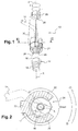
- Figure 1 shows a screw cap 10 according to the invention, which allows in particular to screw a member attachment 12 when such a member is mounted around an element tubular, still designated as an elongated piece 14 generally extending vertically upwards.
- the screwing bit 10 has at its end upper head 20 for the rotational drive of the nozzle 10 around a vertical axis X-X and, at its end lower, a sleeve 22, said clamping sleeve.
- the drive head 20 here comprises a housing 28 of square section forming a female part in which is axially engaged a male part, of complementary shape, belonging to one of the means for the rotational drive of end piece 10.
- the socket 22 has a lateral opening or housing 24 which is open, on the one hand radially to allow the passage of the tubular element 14 and, on the other hand, axially down to allow the introduction of the male part 16 of the fixing member 12 which is received in a female part 26 complementary to housing 24.
- the drive head 20 and the socket 22 are coaxial and the intermediate part is made up by a vertical rod 30 parallel to the axis common to the head 20 and to the socket 22, and which is eccentrically radially with respect to this axis.
- Figure 1 corresponds to the prior positioning of the screwing bit 10, that is to say the radial engagement of the elongated part 14 in the housing 24 of the socket 22.
- the amplitude of the rotational movement so that the facets of the housing 24 engage with the flaps of nut 16 is determined by the number and dimensions of these facets.
- the screwing bit 10 is then mobile in rotation between two opposite angular positions which correspond to the abutment of the vertical rod 30 against the tubular element 14 and which define the angular travel maximum tightening (Dmax) of the nozzle.
- the screwdriver bit 10 can be rotated by a screwing device 34 comprising motorized means, such than an electric screwdriver visible in Figure 3.
- Rotational drive and torque transmission is done for example by cooperation of forms between the housing 28 of the drive head 20 and a male part 32 of the drive device, which is of complementary shape, and axially engaged in the female part.
- the tip 10 is rotated by manual means such as a torque wrench.
- the screwing device 34 comprises a programmable controller (not shown) especially for motorized means control.
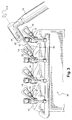
- FIG. 3 shows an example of implementation particular of the invention for fixing the supply pipes 14 in pressurized fuel of an internal combustion engine 36.
- Each supply pipe 14 has here at their ends a fixing member 12.
- Each fixing member 12 is mounted for rotation around the pipe 14 and has a male upper part 16 forming a nut and a threaded lower part 18 intended to be screwed into a tapped hole 38 complementary to the cylinder head 40 motor 36.
- the motor 36 here comprises four supply pipes 14 which are represented at different stages of screwing in the engine 40.
- the fasteners 12 of the pipes are screwed manually or using a key by an operator before final tightening using a screwing 32 comprising a tip 10 according to a method of command which will be described below.
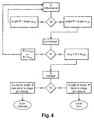
- the initialization step a) comprises a step consisting in set as a setpoint angle value ( ⁇ ), a value minimum ( ⁇ min) greater than the maximum value ( ⁇ max) of so that the result of the comparison generates systematically an error to be corrected, before proceed to the screwing step b) with a tightening stroke maximum (Dmax).
- an intermediate step is planned. handling of the error consisting in axially engaging the fixing in the lateral opening or housing of the socket tightening and rotating the nozzle in the direction of unscrewing, by making at least one angle measurement so to verify that after the axial engagement of the member in the socket the nozzle is always positioned as close as possible to the element tubular and compare the value of the angle ( ⁇ ) measured with the value of the minimum setpoint angle ( ⁇ min) and to not authorize the go to the screwing stage b) only if the value of the angle ( ⁇ ) measured is less than or equal to the value of the minimum angle ( ⁇ min).
- the value of the setpoint torque causing the stop of the rotational drive of the nozzle 10 is notably achieved when the intermediate part 30 abuts against the element tubular 14.
- the rotational drive of the bit tightening 10 is stopped if a nominal torque value of tightening is reached and / or if, during the tightening stroke, the value of the angle traveled reaches a value of safety angle.
- the method comprises a step additional pre-preview with monitoring the torque and the angle before proceeding with the proper tightening says, so this complementary step comes after the step initialization a) and ensures that the angle ( ⁇ ) is correct within the range of desired values [ ⁇ min, ⁇ max].
- the operator checks beforehand whether the organ 12 is in the situation of screwing grip on the support 40.
- the control of obtaining the final positioning of the socket 22 is thus obtained by repeating the screwing step b) to ensure that the stop was not due to a exceeding the safety angle value without the value nominal tightening torque has been reached.
- the automaton includes means such as an audible or light signal, to inform the operator that correct tightening cycle has been performed.
Landscapes
- Engineering & Computer Science (AREA)
- Mechanical Engineering (AREA)
- Details Of Spanners, Wrenches, And Screw Drivers And Accessories (AREA)
Abstract
Description
- des moyens motorisés ;
- des moyens de mesure du couple de serrage ;
- des moyens de mesure de l'angle parcouru durant la course de vissage.
- pendant la phase d'initialisation, on mesure en permanence le couple de serrage et/ou l'angle parcouru par l'embout, et on compare ces mesures à des valeurs de couple et d'angle de consigne ;
- on arrête d'entraíner en rotation l'embout dès lors que le résultat de ladite comparaison indique que la valeur du couple de serrage transmis atteint la valeur du couple de consigne ;
- la valeur du couple de consigne provoquant l'arrêt de l'entraínement en rotation de l'embout est atteinte lorsque la partie intermédiaire vient en butée contre l'élément tubulaire ;
- durant le vissage, l'entraínement en rotation de l'embout de vissage est arrêté si une valeur de couple nominal de serrage est atteinte ou si, lors de la course de vissage, la valeur de l'angle parcouru atteint une valeur d'angle de sécurité ;
- comporte une étape complémentaire de prévissage supplémentaire avec surveillance du couple et de l'angle avant le vissage proprement dit ;
- l'étape complémentaire intervient après l'étape d'initialisation ;
- on vérifie préalablement si l'organe de fixation est en situation d'approche de vissage sur le support.
- la figure 1 est une vue en perspective d'un embout de vissage selon un exemple de réalisation de l'invention ;
- la figure 2 est une vue en coupe selon le plan horizontal II-II de la figure 1 ;
- la figure 3 est une vue en perspective illustrant la mise en oeuvre d'un dispositif de vissage comportant un embout selon l'invention et du procédé de commande d'un tel dispositif, au serrage des tuyaux d'alimentation en carburant d'un moteur à combustion interne ;
- la figure 4 est un diagramme du procédé de commande de vissage selon l'invention.
Claims (14)
- Embout de vissage (10) d'un organe de fixation (12) d'un élément tubulaire (14) sur un support (40), comprenant une tête d'entraínement (20), une douille de serrage (22) recevant l'organe de fixation (12) et une partie intermédiaire (30), caractérisé en ce que la tête d'entraínement (20) et la douille de serrage (22) sont coaxiales, et en ce que la partie intermédiaire (30) est décalée axialement par rapport à celle-ci.
- Embout de vissage (10) selon la revendication 1, caractérisé en ce que la douille de serrage (22) comporte une ouverture latérale (24) permettant le passage de l'élément tubulaire (14).
- Embout de vissage (10) selon la revendication 1 ou 2, caractérisé en ce que sa course angulaire est délimitée par la mise en butée de la partie intermédiaire (30) de part et d'autre de l'élément tubulaire (14).
- Dispositif de vissage du type comportant un embout (10) selon l'une quelconque des revendications précédentes, caractérisé en ce qu'il comporte des moyens motorisés (32)..
- Dispositif de vissage selon la revendication 4, caractérisé en ce qu'il comporte des moyens de mesure du couple de serrage.
- Dispositif de vissage selon la revendication 4 ou 5, caractérisé en ce qu'il comporte des moyens de mesure de l'angle parcouru durant la course de vissage.
- Procédé de commande du serrage d'un organe de fixation (12) d'un élément tubulaire (14) au moyen d'un dispositif de vissage selon l'une quelconque des revendications 4 à 6, caractérisé en ce qu'il comporte successivement :a) une étape d'initialisation ou de mise à zéro au cours de laquelle, après avoir engagé radialement l'élément tubulaire (14) dans l'ouverture latérale (24) de la douille de serrage (22), sans engager axialement l'organe de fixation (12) dans l'ouverture latérale (24) de la douille (22), on entraíne l'embout de vissage (10) en rotation, dans le sens du dévissage, jusqu'à ce que la partie intermédiaire (30) vienne angulairement en butée contre l'élément tubulaire (14) ;b) une étape de vissage de l'organe de fixation (12) au cours de laquelle, après avoir introduit axialement l'organe de fixation (12, 16) dans l'ouverture latérale (24) de la douille de serrage (22), on entraíne l'embout (10) en rotation, dans le sens du vissage selon une course angulaire qui est inférieure ou égale à une course maximale de vissage (Dmax).
- Procédé de commande selon la revendication 7, caractérisé en ce que pendant la phase d'initialisation, on mesure en permanence le couple de serrage et/ou l'angle parcouru par l'embout, et on compare ces mesures à des valeurs de couple et d'angle de consigne.
- Procédé de commande selon la revendication 8, caractérisé en ce qu'on arrête d'entraíner en rotation l'embout (10) dès lors que le résultat de ladite comparaison indique que la valeur du couple de serrage transmis atteint la valeur du couple de consigne.
- Procédé de commande selon la revendication 9, caractérisé en ce que la valeur du couple de consigne provoquant l'arrêt de l'entraínement en rotation de l'embout (10) est atteinte lorsque la partie intermédiaire (30) vient en butée contre l'élément tubulaire (14).
- Procédé de commande selon la revendication 7, caractérisé en ce que durant le vissage, l'entraínement en rotation de l'embout de vissage (10) est arrêté si une valeur de couple nominal de serrage est atteinte ou si, lors de la course de vissage, la valeur de l'angle parcouru atteint une valeur d'angle de sécurité.
- Procédé de commande selon l'une quelconque des revendications 7 à 11, caractérisé en ce qu'il comporte une étape complémentaire de prévissage supplémentaire avec surveillance du couple et de l'angle avant le vissage proprement dit.
- Procédé de commande selon la revendication 12, caractérisé en ce que l'étape complémentaire intervient après l'étape d'initialisation.
- Procédé de commande selon l'une quelconque des revendications 7 à 13, caractérisé en ce qu'on vérifie préalablement si l'organe de fixation (12) est en situation d'approche de vissage sur le support (18).
Applications Claiming Priority (2)
| Application Number | Priority Date | Filing Date | Title |
|---|---|---|---|
| FR0301716A FR2851187B1 (fr) | 2003-02-13 | 2003-02-13 | Embout, dispositif de vissage et procede de commande d'un tel dispositif |
| FR0301716 | 2003-02-13 |
Publications (1)
| Publication Number | Publication Date |
|---|---|
| EP1447176A1 true EP1447176A1 (fr) | 2004-08-18 |
Family
ID=32669363
Family Applications (1)
| Application Number | Title | Priority Date | Filing Date |
|---|---|---|---|
| EP04290241A Withdrawn EP1447176A1 (fr) | 2003-02-13 | 2004-01-30 | Embout, dispositif de vissage et procédé de commande d'un tel dispositif |
Country Status (2)
| Country | Link |
|---|---|
| EP (1) | EP1447176A1 (fr) |
| FR (1) | FR2851187B1 (fr) |
Cited By (6)
| Publication number | Priority date | Publication date | Assignee | Title |
|---|---|---|---|---|
| EP1690635A3 (fr) * | 2005-02-15 | 2006-08-30 | Minimax GmbH & Co KG | Dispositif et procédé pour monter des pulverisateur à l'aide d'une machine-outil |
| FR2964893A1 (fr) * | 2010-09-17 | 2012-03-23 | Airbus Operations Sas | Clef de serrage d'ecrous a trous radiaux |
| IT201700045658A1 (it) * | 2017-04-28 | 2018-10-28 | Gianluca Straccamore | Bussola per montaggio e smontaggio del rubinetto antincendio uni45 |
| IT201700045639A1 (it) * | 2017-04-28 | 2018-10-28 | Gianluca Straccamore | Bussola per montaggio e smontaggio del rubinetto antincendio uni 70 |
| EP3395503A1 (fr) * | 2017-04-28 | 2018-10-31 | Gianluca Straccamore | Douille de clé pour soupape de borne d'incendie |
| CN109955195A (zh) * | 2019-04-16 | 2019-07-02 | 中国科学院声学研究所 | 一种用于端部带有导线引出线的螺纹紧固件的拆装工具 |
Citations (5)
| Publication number | Priority date | Publication date | Assignee | Title |
|---|---|---|---|---|
| US4393583A (en) * | 1981-03-17 | 1983-07-19 | Motorola Inc. | Anti-torque connection apparatus and method for using |
| US4749251A (en) * | 1985-07-11 | 1988-06-07 | Hughes Aircraft Company | Connector locking system |
| US6122997A (en) * | 1994-08-26 | 2000-09-26 | Altura; Dan | Adapter for precise tightening of fluid tube fittings |
| DE20106916U1 (de) * | 2001-04-20 | 2002-08-29 | Weidmüller Interface GmbH & Co., 32760 Detmold | Werkzeug zum Lösen oder Anziehen von mit überwurfmutterartigen Schraubhülsen versehenen Steckern, wobei die Schraubhülsen außenseitig mit einer Rändelung versehen sind |
| US6474201B1 (en) * | 2000-05-02 | 2002-11-05 | Victory In Jesus Ministries, Inc. | Tool for attaching and removing swivel fittings |
-
2003
- 2003-02-13 FR FR0301716A patent/FR2851187B1/fr not_active Expired - Fee Related
-
2004
- 2004-01-30 EP EP04290241A patent/EP1447176A1/fr not_active Withdrawn
Patent Citations (5)
| Publication number | Priority date | Publication date | Assignee | Title |
|---|---|---|---|---|
| US4393583A (en) * | 1981-03-17 | 1983-07-19 | Motorola Inc. | Anti-torque connection apparatus and method for using |
| US4749251A (en) * | 1985-07-11 | 1988-06-07 | Hughes Aircraft Company | Connector locking system |
| US6122997A (en) * | 1994-08-26 | 2000-09-26 | Altura; Dan | Adapter for precise tightening of fluid tube fittings |
| US6474201B1 (en) * | 2000-05-02 | 2002-11-05 | Victory In Jesus Ministries, Inc. | Tool for attaching and removing swivel fittings |
| DE20106916U1 (de) * | 2001-04-20 | 2002-08-29 | Weidmüller Interface GmbH & Co., 32760 Detmold | Werkzeug zum Lösen oder Anziehen von mit überwurfmutterartigen Schraubhülsen versehenen Steckern, wobei die Schraubhülsen außenseitig mit einer Rändelung versehen sind |
Cited By (7)
| Publication number | Priority date | Publication date | Assignee | Title |
|---|---|---|---|---|
| EP1690635A3 (fr) * | 2005-02-15 | 2006-08-30 | Minimax GmbH & Co KG | Dispositif et procédé pour monter des pulverisateur à l'aide d'une machine-outil |
| FR2964893A1 (fr) * | 2010-09-17 | 2012-03-23 | Airbus Operations Sas | Clef de serrage d'ecrous a trous radiaux |
| IT201700045658A1 (it) * | 2017-04-28 | 2018-10-28 | Gianluca Straccamore | Bussola per montaggio e smontaggio del rubinetto antincendio uni45 |
| IT201700045639A1 (it) * | 2017-04-28 | 2018-10-28 | Gianluca Straccamore | Bussola per montaggio e smontaggio del rubinetto antincendio uni 70 |
| EP3395503A1 (fr) * | 2017-04-28 | 2018-10-31 | Gianluca Straccamore | Douille de clé pour soupape de borne d'incendie |
| CN109955195A (zh) * | 2019-04-16 | 2019-07-02 | 中国科学院声学研究所 | 一种用于端部带有导线引出线的螺纹紧固件的拆装工具 |
| CN109955195B (zh) * | 2019-04-16 | 2020-10-23 | 中国科学院声学研究所 | 一种用于端部带有导线引出线的螺纹紧固件的拆装工具 |
Also Published As
| Publication number | Publication date |
|---|---|
| FR2851187A1 (fr) | 2004-08-20 |
| FR2851187B1 (fr) | 2005-05-06 |
Similar Documents
| Publication | Publication Date | Title |
|---|---|---|
| EP0344028B1 (fr) | Dispositif et procédé de vissage et de dévissage d'un écrou sur un élément de liaison | |
| EP3084235A1 (fr) | Fixation temporaire | |
| WO2022008043A1 (fr) | Dispositif de pose de rivet | |
| EP4179220A1 (fr) | Dispositif de pose de fixation temporaire | |
| EP0086703B1 (fr) | Dispositif de pose automatique de systèmes d'assemblage | |
| FR2538740A1 (fr) | Outil universel utilisable comme auxiliaire pour le serrage et/ou le desserrage d'organes vissables et d'outils de serrage | |
| FR2851187A1 (fr) | Embout, dispositif de vissage et procede de commande d'un tel dispositif | |
| WO2022008041A1 (fr) | Dispositif d'enduction | |
| EP4178759A1 (fr) | Dispositif multi-tâche mono-broche à carrousel | |
| EP0072713A2 (fr) | Désagrafeuse d'agrafe d'épinglage à vis | |
| WO2017118960A1 (fr) | Système de serrage et de desserrage d'éléments de fixation et procédés de serrage et de desserrage associés | |
| FR2974024A1 (fr) | Dispositif de maintien d'un bras de prehenseur. | |
| FR3012189A1 (fr) | Dispositif de serrage a douilles multiples | |
| EP3381616B1 (fr) | Extracteur et procede d'extraction d'un injecteur coince dans la culasse d'un moteur de vehicule automobile | |
| FR2470658A1 (fr) | Appareil a cle oleodynamique de serrage servant a devisser et a serrer des ecrous | |
| EP2648877A2 (fr) | Bride de serrage-desserrage | |
| FR3076551A1 (fr) | Dispositif d'application automatique d'une fermeture comportant un filetage interieur sur un recipient pourvu d'un filetage exterieur correspondant, et procede d'application a l'aide dudit dispositif | |
| FR2860746A1 (fr) | Dispositif d'implantation de tige filetee dans un trou taraude, notamment a travers un actionneur de tension annulaire, et procede d'implantation associe. | |
| EP1462214B1 (fr) | Procédé de vérification du positionnement d'une pièce mécanique dans un support et dispositif associé | |
| FR2935664A1 (fr) | Systeme de direction en particulier pour vehicule automobile, comprenant un arbre de direction s'emboitant dans un percage d'un moyeu d'un volant | |
| EP1216120A1 (fr) | Outil d'entrainement en rotation pour un organe de vissage | |
| BE1014382A5 (fr) | Mandrin de retenue pour le serrage d'un tube de verre. | |
| FR2820668A1 (fr) | Dispositif pour le vissage d'une vis equipee ou non d'une rondelle ou analogue de forme quelconque | |
| FR2923426A1 (fr) | Adaptateur pour un outil de vissage mecanise, et son utilisation pour la fixation d'une traverse avant de berceau sous une caisse de vehicule automobile. | |
| WO1985000634A1 (fr) | Pince de puissance pour le vissage des tiges de forage |
Legal Events
| Date | Code | Title | Description |
|---|---|---|---|
| PUAI | Public reference made under article 153(3) epc to a published international application that has entered the european phase |
Free format text: ORIGINAL CODE: 0009012 |
|
| AK | Designated contracting states |
Kind code of ref document: A1 Designated state(s): AT BE BG CH CY CZ DE DK EE ES FI FR GB GR HU IE IT LI LU MC NL PT RO SE SI SK TR |
|
| AX | Request for extension of the european patent |
Extension state: AL LT LV MK |
|
| 17P | Request for examination filed |
Effective date: 20050124 |
|
| AKX | Designation fees paid |
Designated state(s): BE DE ES GB IT |
|
| GRAJ | Information related to disapproval of communication of intention to grant by the applicant or resumption of examination proceedings by the epo deleted |
Free format text: ORIGINAL CODE: EPIDOSDIGR1 |
|
| GRAP | Despatch of communication of intention to grant a patent |
Free format text: ORIGINAL CODE: EPIDOSNIGR1 |
|
| GRAP | Despatch of communication of intention to grant a patent |
Free format text: ORIGINAL CODE: EPIDOSNIGR1 |
|
| RTI1 | Title (correction) |
Free format text: METHOD FOR CONTROLLING A FASTENING DEVICE |
|
| STAA | Information on the status of an ep patent application or granted ep patent |
Free format text: STATUS: THE APPLICATION IS DEEMED TO BE WITHDRAWN |
|
| 18D | Application deemed to be withdrawn |
Effective date: 20061120 |