EP1447062A2 - Beinprothese - Google Patents
Beinprothese Download PDFInfo
- Publication number
- EP1447062A2 EP1447062A2 EP03028600A EP03028600A EP1447062A2 EP 1447062 A2 EP1447062 A2 EP 1447062A2 EP 03028600 A EP03028600 A EP 03028600A EP 03028600 A EP03028600 A EP 03028600A EP 1447062 A2 EP1447062 A2 EP 1447062A2
- Authority
- EP
- European Patent Office
- Prior art keywords
- knee joint
- prosthesis
- leg
- foot
- flexion
- Prior art date
- Legal status (The legal status is an assumption and is not a legal conclusion. Google has not performed a legal analysis and makes no representation as to the accuracy of the status listed.)
- Granted
Links
Images


Classifications
-
- A—HUMAN NECESSITIES
- A61—MEDICAL OR VETERINARY SCIENCE; HYGIENE
- A61F—FILTERS IMPLANTABLE INTO BLOOD VESSELS; PROSTHESES; DEVICES PROVIDING PATENCY TO, OR PREVENTING COLLAPSING OF, TUBULAR STRUCTURES OF THE BODY, e.g. STENTS; ORTHOPAEDIC, NURSING OR CONTRACEPTIVE DEVICES; FOMENTATION; TREATMENT OR PROTECTION OF EYES OR EARS; BANDAGES, DRESSINGS OR ABSORBENT PADS; FIRST-AID KITS
- A61F2/00—Filters implantable into blood vessels; Prostheses, i.e. artificial substitutes or replacements for parts of the body; Appliances for connecting them with the body; Devices providing patency to, or preventing collapsing of, tubular structures of the body, e.g. stents
- A61F2/50—Prostheses not implantable in the body
- A61F2/60—Artificial legs or feet or parts thereof
-
- A—HUMAN NECESSITIES
- A61—MEDICAL OR VETERINARY SCIENCE; HYGIENE
- A61F—FILTERS IMPLANTABLE INTO BLOOD VESSELS; PROSTHESES; DEVICES PROVIDING PATENCY TO, OR PREVENTING COLLAPSING OF, TUBULAR STRUCTURES OF THE BODY, e.g. STENTS; ORTHOPAEDIC, NURSING OR CONTRACEPTIVE DEVICES; FOMENTATION; TREATMENT OR PROTECTION OF EYES OR EARS; BANDAGES, DRESSINGS OR ABSORBENT PADS; FIRST-AID KITS
- A61F2/00—Filters implantable into blood vessels; Prostheses, i.e. artificial substitutes or replacements for parts of the body; Appliances for connecting them with the body; Devices providing patency to, or preventing collapsing of, tubular structures of the body, e.g. stents
- A61F2/50—Prostheses not implantable in the body
- A61F2/68—Operating or control means
- A61F2/70—Operating or control means electrical
Definitions
- the present invention relates to a leg prosthesis for adaptation a thigh stump, as known from DE-A-199 53 972 is.
- This consists of an adapter for a knee joint, which with a stem part is anchored in the patient's femoral stump. Distal occurs the adapter from the thigh stump and offers one there Coupling possibility for an artificial knee joint like this is known for example from EP-B-0 358 056.
- a prosthetic lower leg is coupled to the knee joint, which in turn carries a hinged prosthetic foot distally. This can be swiveled from a pointed foot position to a heel foot position.
- the knee joint according to the proposal of EP-B-0 358 056 is designed that there is a transition from the stretched position to the flexion position a combined rolling and sliding movement around a swivel axis performs.
- the knee joint is the generic leg prosthesis so designed that the distance of a dorsal seen in front of the pivot axis Point of the knee joint to the end of the lower leg of the prosthesis steadily reduced. In other words, the distance increases one, however, seen ventrally in front of the swivel axis Point at the end of the lower leg of the prosthesis.
- Another problem for patients with partially amputated thighs is others that when walking with the healthy foot into a stronger one Pointed foot position must go to the prosthetic foot when reapplying Step forward with the prosthetic leg. This applies regardless of whether the prosthetic foot on the lower leg of the prosthesis is now pivotable or firmly locked.
- the need the healthy natural foot in a reinforced or extreme To bring a pointed foot position so that the prosthesis can swing requires a rather unphysiological way of moving and accompanying it a heavy strain on the spine.
- This task is solved in that every bending position of the knee joint by a converter into a unique electrical signal is implemented, which is a programmable control device is supplied, which generates a signal with which an electrical adjustable actuator that controls the resistance of the knee joint against or for further diffraction according to the signal enlarged or reduced.
- the power transmission element from one on the knee joint and on the Prosthesis foot articulated push rod is constructed.
- the push rod can end, for example, in the dorsal region of the Knee joint to be articulated to reduce the Distance of the articulation point to the end of the lower leg of the prosthesis for the execution of the pivoting movement of the prosthetic foot from the Use the starting position in the desired heel foot position.
- the prosthetic foot is particularly reliable in the heel foot position the movement of the knee from the extension to the flexion position moves when the prosthetic leg according to an advantageous development is designed so that the prosthetic foot on the lower leg of the prosthesis pivotable about a ventral pivot point is coupled and that the power transmission element to the Prosthesis foot is articulated at a dorsal bearing point.
- the Power transmission element then causes the introduction of a torque around the ventral pivot point, whereby the prosthetic foot swings securely into the heel foot position.
- the reins essentially take on the task of natural ones Achilles tendon.
- the main task of the reins is in the stretched position of the knee to return the foot to its original position.
- the rein is used due to the adjustment option its effective length, for example by using a stop a thread with which the relevant end of the rein is screwable, for individual adjustment of a pointed foot position of the prosthetic foot. This setting usually differs by the different heels from patient to patient.
- a reset element is preferably in the force transmission element integrated, which when the knee is extended to the previous Flexion actively restores the prosthetic foot to its original position spends.
- This active reset element supports the effect of the reins mentioned above when movement begins from the Flexion in the extended position of the knee. It unfolds primarily the mentioned power transmission element, the restoring effect, whereas when the reins are almost in the first position Line unfolds its effect.
- the reset element a guide sleeve receiving a spiral spring and has a stamp guided in the sleeve as part of the push rod, such that with increasing knee flexion the Spring is increasingly under pressure and when the knee is stretched the spring force the prosthetic foot in the starting position pivoted. So the more the knee is bent, the higher Spring forces are generated in the restoring element. It is beneficial provided that the guide sleeve in a on the lower leg of the prosthesis attached housing is mounted. This results in a compact unit that is relatively uniform for the patient to handle is.
- the electrically adjustable actuator this is it particularly preferably as a hydraulic cylinder with several controllable Valves trained. That said, every bend position of the knee joint an unambiguously representative electrical signal from the converter is used for further processing in the control device Control of the electrically controllable valves, which in turn control the flow the hydraulic fluid of the cylinder. Through the hydraulic Control is the force with which the piston of the hydraulic cylinder can be moved, controlled.
- Actuators other than a hydraulic cylinder are conceivable, such as for example a magnetic brake.
- the only decisive factor is that the Actuator the resistance of the knee joint for or against another Diffraction controls.
- the forces generated by the actuator are over a suitable mechanics, such as at least one arrangement a pushing band engaging on the upper part of the knee joint, realized.
- the foot via the power transmission element from the pointed foot position steadily pivoted into a heel foot position and every flexion position resistance to or for further diffraction of the Associated knee joint. This ensures the targeted bionic Movement.
- the transducer has a unique signal for each flexion position should generate, the flexion movement is preferably in a translational Movement of a measuring block guided in guide rails um, which in a sensor assigned to it that the flexion position of the Knee joint representative signal generated.
- the measuring block is preferably in with the at least one push belt Connection with which the actuator the force generated by it in the Knee joint guides.
- the converter generated signal which results in a patient-specific Signal generated.
- There is an individual movement for each patient programmable that means every bending position of the knee joint Resistance can be individually assigned to the patient, which is generated by the actuator.
- This is like a look-up table generated table is determined manually, for example the effective length of the mentioned flexible rein, but also the resistance of the actuator in certain flexion positions of the knee joint can be adjusted.
- the values determined in this way can then be entered in the programmable control device, for example by means of a Laptops are saved and are then ready for operation.
- the converter is particularly preferably designed such that the measuring block is a magnet and the sensor assigned to it is a Hall sensor, to which the magnet that is attached to the push band for transferring the Actuator forces is connected, is guided past.
- the big advantage this arrangement is that it is absolutely wear-free.
- the power supply of the control device, the actuator and possibly the The converter can be placed in the prosthesis or batteries Batteries are done.
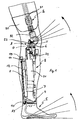
- the prosthetic leg consists of an adapter 2, which is connected to the thigh stump 30 of the patient is connected in such a way that the Adapter 2 is fixed to the femur stump 31.
- a knee joint 3 is coupled to which distally a prosthetic lower leg 4 connects, which finally carries a prosthetic foot 5 in such a way that the prosthetic foot 5 with the lower leg 4 is pivotally connected.
- the knee joint 3 has a pivot axis 6, about which the Thigh part of the knee joint 3 opposite the lower leg part 4 is pivotable.
- the knee joint 3 has the special property that it in the transition from the stretched position to the flexion layer around the Swivel axis 6 performs a roll-slide movement. This leads to, that the distance of a dorsally seen in front of the pivot axis 6 point D to the end 7 of the lower leg 4 steadily reduced. The said distance increases accordingly at a point located ventrally in front of the pivot axis 6 V steadily when executing the movement from the stretching to the bending position of the knee joint 3.
- the prosthetic foot 5 is around the end 7 of the lower leg 4 of the prosthesis a pivotally located pivot point 9 pivotally hinged. Becomes the prosthetic foot 5 is pivoted about the pivot point 9, moves the prosthetic foot 5 in the heel foot position. This is indicated in FIG. 1 thanks to the radiate wreath in the foot and knee area. Will that Knees bent in the direction of the arrow indicated, so the prosthetic foot raised in the direction of the indicated arrow.
- the coupling of the movement of the knee joint 3 with the movement of the prosthetic foot 5 is achieved via the force transmission element 8, which is articulated proximally to the knee joint 3.
- the force of the power transmission element 8 is in the extension 33 at the bearing point 10 initiated dorsally.
- the extension 33 assumes the function here of the natural upper ankle.
- the rein 12 consists, for example, of a flexible steel strand. He takes over Function of the natural Achilles tendon. It serves the transition from the bend to the extended position of the knee joint 3 the prosthetic foot 5 swivel back completely into the starting position. About that In addition, it serves the individual adjustment of a heel position of the Prosthetic foot 5. To this end, the reins 12 have at the proximal end Threaded sleeve, which with an extension 19 with an internal thread and the bearing 11 cooperates such that the approach 19th forms a stop on the bearing 11. By screwing the Approach 19 allows the starting foot position to be customized Adjust (pointed foot position).
- a reset element in the force transmission element is not shown, that when the knee joint 3 is stretched to the previous one Diffraction pushes the prosthetic foot 5 back into its original position.
- a hydraulic cylinder 21 is now in the lower leg 4 of the prosthesis arranged its piston rod 22.
- the hydraulic cylinder 21 serves as Actuator for adjusting the resistance of the knee joint against or for further diffraction.
- the hydraulic cylinder 21 of multi-chamber valves (not shown) correspondingly with hydraulic fluid provided.
- the multi-chamber valves can be controlled electrically, by a programmable control device (not shown).
- This control device receives a signal from a transducer (not shown) that detects the current flexion position of the Knee joint 3 converted into a unique electrical signal.
- the flexion position of the knee joint 3 is generated accordingly Hydraulic cylinder 21, therefore, a corresponding force that it over his Piston rod 22 passes on.
- At least one push band 23 is attached dorsally to the knee joint 3, the other end with the piston rod 22 of the hydraulic cylinder 21 is connected. Controls at least one push belt 23 via this the hydraulic cylinder 21 the resistance to further diffraction of the knee joint 3.
- a guided in guide rails Measuring block (not shown), which is part of the sensor.
- the measuring block Move the push belt 23 further down. He strokes one Sensor (not shown) past, preferably a Hall sensor, if the measuring block is a magnet, and a signal is generated. This signal uniquely represents the respective one Bending position of the knee joint 3 and the one already mentioned Control device fed for further processing.
- leg prosthesis according to the invention only the existence of a forced coupling between the movement of the Knee joint 3 and the pivoting movement of the prosthetic foot 5, but also that the resistance of the knee joint against or for a further diffraction according to the respective diffraction position of the Knee is enlarged or reduced.
Landscapes
- Health & Medical Sciences (AREA)
- Transplantation (AREA)
- Heart & Thoracic Surgery (AREA)
- Oral & Maxillofacial Surgery (AREA)
- Engineering & Computer Science (AREA)
- Biomedical Technology (AREA)
- Cardiology (AREA)
- Vascular Medicine (AREA)
- Life Sciences & Earth Sciences (AREA)
- Animal Behavior & Ethology (AREA)
- General Health & Medical Sciences (AREA)
- Public Health (AREA)
- Veterinary Medicine (AREA)
- Orthopedic Medicine & Surgery (AREA)
- Prostheses (AREA)
Abstract
Description
- Fig. 1
- die schematische Seitenansicht der vollständigen Beinprothese,
- Fig. 2
- die Ansicht der Prothese von ventral ohne Fuß und
- Fig. 3
- die Ansicht des Kniegelenkes und des Prothesenunterschenkels von dorsal.
Claims (10)
- Beinprothese zur Adaption an einen Oberschenkelstumpf, bestehend aus einem Adapter (2) für ein Kniegelenk (3), einem daran befestigten Kniegelenk (3) und einem am Kniegelenk (3) angekoppelten Prothesenunterschenkel (4) mit einem daran angelenkten Prothesenfuß (5), der in eine Hackenfußlage schwenkbar ist, wobei das Kniegelenk (3) so ausgebildet ist, dass es beim Übergang von der Strecklage in die Beugelage um eine Schwenkachse (6) eine kombinierte Roll-Gleitbewegung ausführt, derart, dass sich der Abstand eines dorsal gesehen vor der Schwenkachse (6) gelegenen Punktes (D) zum Ende (7) des Prothesenunterschenkels (4) mit zunehmender Beugung stetig verkleinert bzw. eines ventral gesehen vor der Schwenkachse (6) gelegenen Punktes (V) zum Ende (7) des Prothesenunterschenkels (4) stetig vergrößert, wobei zwischen wenigstens einem von dorsal gesehen vor der Schwenkachse (6) gelegenen Lagerpunkt bzw. einem ventral gesehen vor der Schwenkachse (6) gelegenen Lagerpunkt und dem Prothesenfuß (5) ein Kraftübertragungselement (8) angeordnet ist, welches den Prothesenfuß (5) beim Beugen des Kniegelenkes (3) in zunehmendem Maße aus der Spitzfußlage in die Hackenfußlage überführt,
dadurch gekennzeichnet, dass jede Beugeposition des Kniegelenkes durch einen Wandler in ein eindeutiges elektrisches Signal umgesetzt wird, welches einer programmierbaren Steuerungseinrichtung zugeführt wird, die ein Signal generiert, mit welchem ein elektrisch verstellbarer Aktuator angesteuert wird, der den Widerstand des Kniegelenkes gegen bzw. für eine weitere Beugung dem Signal entsprechend vergrößert bzw. verkleinert. - Beinprothese nach Anspruch 1, dadurch gekennzeichnet, dass das Kraftübertragungselement (8) aus einer am Kniegelenk (3) und an dem Prothesefuß (5) angelenkten Schubstange aufgebaut ist.
- Beinprothese nach Anspruch 2 oder 3, dadurch gekennzeichnet, dass der Prothesenfuß (5) an den Prothesenunterschenkel (4) um einen ventral gelegenen Schwenkpunkt (9) schwenkbar gekoppelt ist und dass das Kraftübertragungselement (8) an den Prothesenfuß (5) an einem dorsal gelegenen Lagerpunkt (10) angelenkt ist.
- Beinprothese nach einem der Ansprüche 1 bis 3, dadurch gekennzeichnet, dass zwischen dem Prothesenfuß (5) und einem Lager (11) an dem Prothesenunterschenkel (4) ein flexibler, auf seine effektive Länge einstellbarer Zügel (12) gespannt ist, der bei zunehmender Beugung des Kniegelenkes (3) eine zunehmende Lose erhält.
- Beinprothese nach einem der Ansprüche 1 bis 4, dadurch gekennzeichnet, dass in dem Kraftübertragungselement (8) ein Rückstellelement integriert ist, welches bei Streckung des Kniegelenkes (3) nach vorheriger Beugung den Prothesenfuß (5) wieder in seine Ausgangslage (Spitzfußlage) verbringt.
- Beinprothese nach Anspruch 5, dadurch gekennzeichnet, dass das Rückstellelement eine eine Spiralfeder aufnehmende Führungshülse sowie einen in der Hülse geführten Stempel als Teil der Schubstange aufweist, derart, dass bei zunehmender Beugung des Kniegelenks (3) die Feder zunehmend druckbelastet wird und bei Streckung des Kniegelenkes (3) die Federkraft den Prothesenfuß (5) in die Ausgangsposition verschwenkt.
- Beinprothese nach Anspruch 6, dadurch gekennzeichnet, dass die Führungshülse in einem an den Prothesenunterschenkel (4) befestigten Gehäuse gelagert ist.
- Beinprothese nach einem der Ansprüche 1 bis 7, dadurch gekennzeichnet, dass der Aktuator ein Hydraulikzylinder mit mehreren steuerbaren Ventilen ist.
- Beinprothese nach einem der Ansprüche 1 bis 8, dadurch gekennzeichnet, dass der Wandler die Beugebewegung umsetzt in eine translatorische Bewegung eines in Führungsleisten geführten Messblockes, der in einem ihm zugeordneten Sensor das die Beugeposition des Kniegelenkes repräsentierende Signal erzeugt.
- Beinprothese nach Anspruch 9, dadurch gekennzeichnet, dass der Messblock ein Magnet und der Sensor ein Hallsensor ist.
Applications Claiming Priority (2)
| Application Number | Priority Date | Filing Date | Title |
|---|---|---|---|
| DE10307328A DE10307328A1 (de) | 2003-02-17 | 2003-02-17 | Beinprothese |
| DE10307328 | 2003-02-17 |
Publications (3)
| Publication Number | Publication Date |
|---|---|
| EP1447062A2 true EP1447062A2 (de) | 2004-08-18 |
| EP1447062A3 EP1447062A3 (de) | 2005-05-04 |
| EP1447062B1 EP1447062B1 (de) | 2006-05-24 |
Family
ID=32668114
Family Applications (1)
| Application Number | Title | Priority Date | Filing Date |
|---|---|---|---|
| EP03028600A Expired - Lifetime EP1447062B1 (de) | 2003-02-17 | 2003-12-12 | Beinprothese |
Country Status (6)
| Country | Link |
|---|---|
| US (1) | US6955692B2 (de) |
| EP (1) | EP1447062B1 (de) |
| JP (1) | JP2004249102A (de) |
| AT (1) | ATE326929T1 (de) |
| DE (2) | DE10307328A1 (de) |
| ES (1) | ES2261861T3 (de) |
Cited By (9)
| Publication number | Priority date | Publication date | Assignee | Title |
|---|---|---|---|---|
| CN100492444C (zh) * | 2005-07-12 | 2009-05-27 | 四川大学 | 人体模型的仿生关节结构及其用途 |
| WO2010064063A1 (en) * | 2008-04-30 | 2010-06-10 | Rizzoli Ortopedia S.P.A. | Automatic prosthesis for above-knee amputees |
| WO2011057791A1 (de) * | 2009-11-13 | 2011-05-19 | Otto Bock Healthcare Products Gmbh | Vorrichtung und verfahren zur steuerung eines künstlichen orthetischen oder prothetischen gelenkes |
| US8366788B2 (en) | 2004-09-02 | 2013-02-05 | Blatchford Products Limited | Control system for a lower limb prosthesis or orthosis |
| US8403997B2 (en) | 2006-03-24 | 2013-03-26 | Blatchford Products Limited | Lower limb prosthesis and control unit |
| WO2016169850A1 (de) * | 2015-04-24 | 2016-10-27 | Otto Bock Healthcare Products Gmbh | Verfahren zur steuerung einer dämpfungsveränderung bei einem künstlichen gelenk |
| WO2019228769A1 (de) * | 2018-05-28 | 2019-12-05 | Johannes Klopf | Oberschenkelprothesenpassteil |
| WO2020016014A1 (de) * | 2018-07-18 | 2020-01-23 | Ottobock Se & Co. Kgaa | Orthopädietechnische vorrichtung mit einem fussteil, einem unterschenkelteil und einem oberschenkelteil |
| WO2021037558A1 (de) * | 2019-08-27 | 2021-03-04 | Johannes Klopf | FUßGELENK SOWIE OBERSCHENKELPROTHESENPASSTEIL |
Families Citing this family (68)
| Publication number | Priority date | Publication date | Assignee | Title |
|---|---|---|---|---|
| US7736394B2 (en) * | 2002-08-22 | 2010-06-15 | Victhom Human Bionics Inc. | Actuated prosthesis for amputees |
| US7314490B2 (en) * | 2002-08-22 | 2008-01-01 | Victhom Human Bionics Inc. | Actuated leg prosthesis for above-knee amputees |
| US7815689B2 (en) | 2003-11-18 | 2010-10-19 | Victhom Human Bionics Inc. | Instrumented prosthetic foot |
| US20050107889A1 (en) * | 2003-11-18 | 2005-05-19 | Stephane Bedard | Instrumented prosthetic foot |
| US7896927B2 (en) | 2004-02-12 | 2011-03-01 | össur hf. | Systems and methods for actuating a prosthetic ankle based on a relaxed position |
| CN1929797B (zh) | 2004-02-12 | 2010-05-26 | 奥瑟Hf公司 | 用于运动受控制的足单元的系统和方法 |
| WO2005087144A2 (en) | 2004-03-10 | 2005-09-22 | össur hf | Control system and method for a prosthetic knee |
| US20060136062A1 (en) * | 2004-12-17 | 2006-06-22 | Dinello Alexandre | Height-and angle-adjustable motion disc implant |
| EP1848380B1 (de) | 2004-12-22 | 2015-04-15 | Össur hf | Systeme und verfahren zur bearbeitung der gliedmassenbewegung |
| CN101155557B (zh) * | 2005-02-02 | 2012-11-28 | 奥瑟Hf公司 | 用于监控步态动态的感应系统和方法 |
| WO2006084219A2 (en) | 2005-02-02 | 2006-08-10 | össur hf | Prosthetic and orthotic systems usable for rehabilitation |
| US8801802B2 (en) | 2005-02-16 | 2014-08-12 | össur hf | System and method for data communication with a mechatronic device |
| SE528516C2 (sv) | 2005-04-19 | 2006-12-05 | Lisa Gramnaes | Kombinerat aktivt och passivt benprotessystem samt en metod för att utföra en rörelsecykel med ett sådant system |
| EP1946429B1 (de) | 2005-08-10 | 2017-06-21 | Bionic Power Inc. | Verfahren und vorrichtungen zum gewinnen von biomechanischer energie |
| US7531006B2 (en) | 2005-09-01 | 2009-05-12 | össur hf | Sensing system and method for motion-controlled foot unit |
| US8048172B2 (en) | 2005-09-01 | 2011-11-01 | össur hf | Actuator assembly for prosthetic or orthotic joint |
| WO2007027808A2 (en) | 2005-09-01 | 2007-03-08 | össur hf | System and method for determining terrain transitions |
| BRPI0617500B8 (pt) * | 2005-10-17 | 2021-07-27 | Spidertech A Div Of Stoecker & Associates A Subsidiary Of The Dermatology Center Llc | kit de imunoensaio para a detecção de veneno de loxosceles reclusa |
| US20070162150A1 (en) * | 2006-01-12 | 2007-07-12 | Fago John R | Modular prosthetic implant for upper and lower extremity amputees |
| EP2104476B1 (de) * | 2007-01-05 | 2016-01-06 | Victhom Human Bionics Inc. | Aktivmechanismus mit hohem drehmoment für orthosenvorrichtungen |
| WO2008080234A1 (en) | 2007-01-05 | 2008-07-10 | Victhom Human Bionics Inc. | Joint actuation mechanism for a prosthetic and/or orthotic device having a compliant transmission |
| WO2008086629A1 (en) | 2007-01-19 | 2008-07-24 | Victhom Human Bionics Inc. | Reactive layer control system for prosthetic and orthotic devices |
| US20080269912A1 (en) * | 2007-04-26 | 2008-10-30 | Rego Florida Corporation | Artificial leg |
| WO2009120637A1 (en) | 2008-03-24 | 2009-10-01 | Ossur Hf | Transfemoral prosthetic systems and methods for operating the same |
| US8366789B2 (en) * | 2008-05-28 | 2013-02-05 | 3D Systems, Inc. | Prosthetic limb |
| US11007070B2 (en) | 2008-11-09 | 2021-05-18 | 3D Systems, Inc. | Modular custom braces, casts and devices and methods for designing and fabricating |
| US8613716B2 (en) | 2008-11-09 | 2013-12-24 | 3D Systems, Inc. | Custom braces, casts and devices having limited flexibility and methods for designing and fabricating |
| CN101570219B (zh) * | 2009-06-08 | 2010-12-01 | 南京航空航天大学 | 具有三维力感知及空间表面自适应能力的仿生腿 |
| US8915968B2 (en) | 2010-09-29 | 2014-12-23 | össur hf | Prosthetic and orthotic devices and methods and systems for controlling the same |
| US9060884B2 (en) | 2011-05-03 | 2015-06-23 | Victhom Human Bionics Inc. | Impedance simulating motion controller for orthotic and prosthetic applications |
| US8736087B2 (en) | 2011-09-01 | 2014-05-27 | Bionic Power Inc. | Methods and apparatus for control of biomechanical energy harvesting |
| WO2013043264A1 (en) * | 2011-09-20 | 2013-03-28 | Smith Larry N | Implantable prosthetic device for distribution of weight on amputated limb and method of use with an external prosthetic device |
| US8882851B2 (en) | 2011-09-20 | 2014-11-11 | Larry Nelson Smith | Implantable prosthetic device for distribution of weight on amputated limb and method of use with an external prosthetic device |
| US9737419B2 (en) | 2011-11-02 | 2017-08-22 | Bionx Medical Technologies, Inc. | Biomimetic transfemoral prosthesis |
| US10543109B2 (en) | 2011-11-11 | 2020-01-28 | Össur Iceland Ehf | Prosthetic device and method with compliant linking member and actuating linking member |
| US9532877B2 (en) | 2011-11-11 | 2017-01-03 | Springactive, Inc. | Robotic device and method of using a parallel mechanism |
| CN102512270B (zh) * | 2011-12-31 | 2014-02-19 | 河北工业大学 | 假肢膝关节运动的控制方法 |
| US9017419B1 (en) | 2012-03-09 | 2015-04-28 | össur hf | Linear actuator |
| CN104066404B (zh) * | 2012-03-09 | 2015-07-29 | 纳博特斯克有限公司 | 多连杆膝部联结器 |
| US9044346B2 (en) | 2012-03-29 | 2015-06-02 | össur hf | Powered prosthetic hip joint |
| WO2013188510A2 (en) * | 2012-06-12 | 2013-12-19 | Iwalk, Inc. | Prosthetic, orthotic or exoskeleton device |
| DE102012015483B3 (de) * | 2012-08-07 | 2014-01-16 | Otto Bock Healthcare Gmbh | Elektrodenanordnung für eine Plasmabehandlung und Vorrichtung zur Herstellung einer transkutanen Verbindung |
| JP2015529574A (ja) | 2012-09-17 | 2015-10-08 | プレジデント アンド フェローズ オブ ハーバード カレッジ | 人間動作を補助するための軟性外骨格スーツ |
| US8932367B2 (en) | 2013-02-13 | 2015-01-13 | Larry N. Smith | Shock absorbing implantable limb prosthetic |
| CN105228559B (zh) | 2013-02-26 | 2018-01-09 | 奥苏尔公司 | 具有增强的稳定性和弹性能恢复的假足 |
| EP2967920B1 (de) | 2013-03-14 | 2021-04-21 | Ossur Hf | Knöchelprothese: verfahren zur steuerung auf basis einer geschwindigkeitsanpassung |
| JP6466420B2 (ja) | 2013-05-31 | 2019-02-06 | プレジデント アンド フェローズ オブ ハーバード カレッジ | 人間動作を補助するための軟性外骨格スーツ |
| KR20160098354A (ko) | 2013-12-09 | 2016-08-18 | 프레지던트 앤드 펠로우즈 오브 하바드 칼리지 | 보조 가요성 수트들, 가요성 수트 시스템들, 및 사람의 이동을 돕기 위해 이들을 만들고 제어하는 방법들 |
| US10278883B2 (en) | 2014-02-05 | 2019-05-07 | President And Fellows Of Harvard College | Systems, methods, and devices for assisting walking for developmentally-delayed toddlers |
| EP3128963A4 (de) | 2014-04-10 | 2017-12-06 | President and Fellows of Harvard College | Orthopädische vorrichtung mit vorstehenden elementen |
| WO2015157723A1 (en) | 2014-04-11 | 2015-10-15 | össur hf | Prosthetic foot with removable flexible members |
| DE102015010221B4 (de) | 2014-09-05 | 2017-11-16 | Carl Haasper | Kniegelenk-Endoprothese |
| EP3194769B1 (de) | 2014-09-19 | 2020-04-08 | President and Fellows of Harvard College | Weiches exoskelett zur unterstützung von menschlicher bewegung |
| CA2969884C (en) | 2014-12-08 | 2023-03-28 | Rehabilitation Institute Of Chicago | Powered and passive assistive device and related methods |
| US20160296336A1 (en) | 2015-04-07 | 2016-10-13 | Gerhard E. Maale | Torsionally Stabilized Endoprosthetic Device |
| US10390973B2 (en) | 2015-05-11 | 2019-08-27 | The Hong Kong Polytechnic University | Interactive exoskeleton robotic knee system |
| EP3349697B1 (de) | 2015-09-18 | 2025-08-06 | Össur Iceland EHF | Magnetischer verriegelungsmechanismus für prothetische oder orthopädische gelenke |
| US10195099B2 (en) | 2016-01-11 | 2019-02-05 | Bionic Power Inc. | Method and system for intermittently assisting body motion |
| EP3429512A4 (de) | 2016-03-13 | 2019-10-30 | President and Fellows of Harvard College | Flexible elemente zur verankerung am körper |
| EP3487666B1 (de) | 2016-07-22 | 2024-11-13 | President and Fellows of Harvard College | Bedienelementeoptimierung für wearable-systeme |
| EP3496635B1 (de) * | 2016-08-09 | 2022-10-05 | Exactech, Inc. | Vorrichtungen zur verhinderung der gelenkinstabilität nach einer arthroplastie |
| US11014804B2 (en) | 2017-03-14 | 2021-05-25 | President And Fellows Of Harvard College | Systems and methods for fabricating 3D soft microstructures |
| JP7199155B2 (ja) | 2018-04-11 | 2023-01-05 | ナブテスコ株式会社 | 多節リンク膝継手 |
| JP7203509B2 (ja) | 2018-04-11 | 2023-01-13 | ナブテスコ株式会社 | 多節リンク膝継手 |
| DE102018111234B3 (de) * | 2018-05-09 | 2019-08-29 | Otto Bock Healthcare Products Gmbh | Orthopädisches Hilfsmittel |
| KR102161533B1 (ko) * | 2019-01-22 | 2020-10-06 | 국민대학교산학협력단 | 높이 조절이 가능한 로봇 의족 장치 |
| DE102019121234B3 (de) * | 2019-08-06 | 2021-01-07 | Ottobock Se & Co. Kgaa | Orthopädietechnische Vorrichtung |
| DE102020134649A1 (de) | 2020-12-22 | 2022-06-23 | plus medica OT GmbH | Gelenkorthese |
Family Cites Families (14)
| Publication number | Priority date | Publication date | Assignee | Title |
|---|---|---|---|---|
| US2568053A (en) * | 1948-10-07 | 1951-09-18 | John G Catranis | Knee lock mechanism for artificial legs |
| US4051558A (en) * | 1976-06-30 | 1977-10-04 | The United States Of America As Represented By The United States National Aeronautics And Space Administration | Mechanical energy storage device for hip disarticulation |
| US5133773A (en) * | 1988-03-25 | 1992-07-28 | Kabushiki Kaisha Kobe Seiko Sho | Teaching playback swing-phase-controlled above-knee prosthesis |
| DE3830330A1 (de) * | 1988-09-07 | 1990-03-15 | Schuett & Grundei Orthopaedie | Kniegelenk fuer eine beinprothese |
| CA2057108C (en) * | 1991-12-05 | 1996-12-31 | Kelvin B. James | System for controlling artificial knee joint action in an above knee prosthesis |
| JPH05337146A (ja) * | 1992-06-09 | 1993-12-21 | Hyogo Pref Gov Shakai Fukushi Jigyodan | 遊脚相コントロール義足 |
| US6113642A (en) * | 1996-06-27 | 2000-09-05 | Mauch, Inc. | Computer controlled hydraulic resistance device for a prosthesis and other apparatus |
| GB9813904D0 (en) * | 1997-08-15 | 1998-08-26 | Blatchford & Sons Ltd | A lower limb prosthesis |
| DE19754690A1 (de) * | 1997-12-10 | 1999-07-01 | Biedermann Motech Gmbh | Beinprothese mit einem künstlichen Kniegelenk mit einer Regeleinrichtung |
| US6425925B1 (en) * | 1998-10-01 | 2002-07-30 | Schütt & Grundei Orthopädietechnik GmbH | Leg exoprosthesis for adaptation to a thigh stump |
| DE19845191C1 (de) * | 1998-10-01 | 2000-03-16 | Schuett & Grundei Orthopaedie | Beinprothese zur Adaption an einen Oberschenkelstumpf |
| DE19859931A1 (de) * | 1998-12-24 | 2000-07-06 | Biedermann Motech Gmbh | Beinprothese mit einem künstlichen Kniegelenk und Verfahren zur Steuerung einer Beinprothese |
| DE19953972A1 (de) * | 1999-11-10 | 2001-06-13 | Schuett & Grundei Orthopaedie | Beinprothese mit verschwenkbarem Prothesenfuß |
| FI110159B (fi) * | 1999-12-17 | 2002-12-13 | Respecta Oy | Alaraajaproteesi |
-
2003
- 2003-02-17 DE DE10307328A patent/DE10307328A1/de not_active Withdrawn
- 2003-12-12 AT AT03028600T patent/ATE326929T1/de not_active IP Right Cessation
- 2003-12-12 ES ES03028600T patent/ES2261861T3/es not_active Expired - Lifetime
- 2003-12-12 DE DE50303462T patent/DE50303462D1/de not_active Expired - Lifetime
- 2003-12-12 EP EP03028600A patent/EP1447062B1/de not_active Expired - Lifetime
-
2004
- 2004-02-13 JP JP2004035895A patent/JP2004249102A/ja active Pending
- 2004-02-13 US US10/778,383 patent/US6955692B2/en not_active Expired - Lifetime
Cited By (14)
| Publication number | Priority date | Publication date | Assignee | Title |
|---|---|---|---|---|
| US8366788B2 (en) | 2004-09-02 | 2013-02-05 | Blatchford Products Limited | Control system for a lower limb prosthesis or orthosis |
| CN100492444C (zh) * | 2005-07-12 | 2009-05-27 | 四川大学 | 人体模型的仿生关节结构及其用途 |
| US8403997B2 (en) | 2006-03-24 | 2013-03-26 | Blatchford Products Limited | Lower limb prosthesis and control unit |
| WO2010064063A1 (en) * | 2008-04-30 | 2010-06-10 | Rizzoli Ortopedia S.P.A. | Automatic prosthesis for above-knee amputees |
| CN102724936B (zh) * | 2009-11-13 | 2015-06-17 | 奥托·博克保健产品有限公司 | 用于控制人造矫形外科或假肢关节的方法和设备 |
| CN102724936A (zh) * | 2009-11-13 | 2012-10-10 | 奥托·博克保健产品有限公司 | 用于控制人造矫形外科或假肢关节的方法和设备 |
| WO2011057791A1 (de) * | 2009-11-13 | 2011-05-19 | Otto Bock Healthcare Products Gmbh | Vorrichtung und verfahren zur steuerung eines künstlichen orthetischen oder prothetischen gelenkes |
| US9278013B2 (en) | 2009-11-13 | 2016-03-08 | Otto Bock Healthcare Products Gmbh | Device and method for controlling an artificial orthotic or prosthetic joint |
| WO2016169850A1 (de) * | 2015-04-24 | 2016-10-27 | Otto Bock Healthcare Products Gmbh | Verfahren zur steuerung einer dämpfungsveränderung bei einem künstlichen gelenk |
| US10772743B2 (en) | 2015-04-24 | 2020-09-15 | Otto Bock Healthcare Products Gmbh | Method for controlling a change of damping in an artificial joint |
| WO2019228769A1 (de) * | 2018-05-28 | 2019-12-05 | Johannes Klopf | Oberschenkelprothesenpassteil |
| US11857394B2 (en) | 2018-05-28 | 2024-01-02 | Johannes Klopf | Thigh prosthetic component |
| WO2020016014A1 (de) * | 2018-07-18 | 2020-01-23 | Ottobock Se & Co. Kgaa | Orthopädietechnische vorrichtung mit einem fussteil, einem unterschenkelteil und einem oberschenkelteil |
| WO2021037558A1 (de) * | 2019-08-27 | 2021-03-04 | Johannes Klopf | FUßGELENK SOWIE OBERSCHENKELPROTHESENPASSTEIL |
Also Published As
| Publication number | Publication date |
|---|---|
| EP1447062B1 (de) | 2006-05-24 |
| US20040193286A1 (en) | 2004-09-30 |
| ATE326929T1 (de) | 2006-06-15 |
| DE50303462D1 (de) | 2006-06-29 |
| DE10307328A1 (de) | 2004-09-02 |
| US6955692B2 (en) | 2005-10-18 |
| JP2004249102A (ja) | 2004-09-09 |
| HK1071049A1 (en) | 2005-07-08 |
| ES2261861T3 (es) | 2006-11-16 |
| EP1447062A3 (de) | 2005-05-04 |
Similar Documents
| Publication | Publication Date | Title |
|---|---|---|
| EP1447062B1 (de) | Beinprothese | |
| EP0728451B1 (de) | Bremskniegelenk | |
| DE102012023023B4 (de) | Orthopädietechnische Vorrichtung | |
| EP0672398B1 (de) | Schwenkverbindung zwischen Teilen eines orthopädischen Hilfsmittels | |
| EP3731786B1 (de) | Orthopädietechnische einrichtung und verfahren zu deren steuerung | |
| EP3823564B1 (de) | Orthopädietechnische vorrichtung mit einem fussteil, einem unterschenkelteil und einem oberschenkelteil | |
| DE102008008284A1 (de) | Orthopädisches Kniegelenk sowie Verfahren zur Steuerung eines orthopädischen Kniegelenkes | |
| DE102006009510A1 (de) | Hüftgelenkprothese | |
| DE102010019843A1 (de) | Prothesenschaft | |
| EP3212131B1 (de) | Prothese | |
| EP2763628B1 (de) | Protheseneinrichtung | |
| DE102009051668B4 (de) | Kniegelenk für eine Prothese | |
| DE102009056074A1 (de) | Knieexartikulationsprothese | |
| DE19845191C1 (de) | Beinprothese zur Adaption an einen Oberschenkelstumpf | |
| EP1099431B1 (de) | Beinprothese mit verschwenkbarem Prothesenfuss | |
| EP3634321A1 (de) | Orthopädietechnische gelenkeinrichtung | |
| DE10302432A1 (de) | Fingerprothese | |
| EP3243454B1 (de) | Am beckenknochen montierbare abstützvorrichtung | |
| EP3212127B1 (de) | Prothesensystem | |
| DE102021133616A1 (de) | Verfahren zur Steuerung eines prothetischen und/oder orthetischen Systems und ein solches System | |
| DE102015001967A1 (de) | Steuerbare Vorrichtung,insbesondere steuerbare Prothese, steuerbare Orthese oder steuerbares Implantat | |
| EP3829495B1 (de) | Befestigungseinrichtung zur befestigung eines prothesenschaftes an einem prothesenkniegelenk und prothesenkniegelenk | |
| DE314341C (de) |
Legal Events
| Date | Code | Title | Description |
|---|---|---|---|
| PUAI | Public reference made under article 153(3) epc to a published international application that has entered the european phase |
Free format text: ORIGINAL CODE: 0009012 |
|
| AK | Designated contracting states |
Kind code of ref document: A2 Designated state(s): AT BE BG CH CY CZ DE DK EE ES FI FR GB GR HU IE IT LI LU MC NL PT RO SE SI SK TR |
|
| AX | Request for extension of the european patent |
Extension state: AL LT LV MK |
|
| PUAL | Search report despatched |
Free format text: ORIGINAL CODE: 0009013 |
|
| AK | Designated contracting states |
Kind code of ref document: A3 Designated state(s): AT BE BG CH CY CZ DE DK EE ES FI FR GB GR HU IE IT LI LU MC NL PT RO SE SI SK TR |
|
| AX | Request for extension of the european patent |
Extension state: AL LT LV MK |
|
| REG | Reference to a national code |
Ref country code: HK Ref legal event code: DE Ref document number: 1071049 Country of ref document: HK |
|
| 17P | Request for examination filed |
Effective date: 20050603 |
|
| GRAP | Despatch of communication of intention to grant a patent |
Free format text: ORIGINAL CODE: EPIDOSNIGR1 |
|
| AKX | Designation fees paid |
Designated state(s): AT BE BG CH CY CZ DE DK EE ES FI FR GB GR HU IE IT LI LU MC NL PT RO SE SI SK TR |
|
| GRAS | Grant fee paid |
Free format text: ORIGINAL CODE: EPIDOSNIGR3 |
|
| GRAA | (expected) grant |
Free format text: ORIGINAL CODE: 0009210 |
|
| AK | Designated contracting states |
Kind code of ref document: B1 Designated state(s): AT BE BG CH CY CZ DE DK EE ES FI FR GB GR HU IE IT LI LU MC NL PT RO SE SI SK TR |
|
| PG25 | Lapsed in a contracting state [announced via postgrant information from national office to epo] |
Ref country code: SK Free format text: LAPSE BECAUSE OF FAILURE TO SUBMIT A TRANSLATION OF THE DESCRIPTION OR TO PAY THE FEE WITHIN THE PRESCRIBED TIME-LIMIT Effective date: 20060524 Ref country code: SI Free format text: LAPSE BECAUSE OF FAILURE TO SUBMIT A TRANSLATION OF THE DESCRIPTION OR TO PAY THE FEE WITHIN THE PRESCRIBED TIME-LIMIT Effective date: 20060524 Ref country code: FI Free format text: LAPSE BECAUSE OF FAILURE TO SUBMIT A TRANSLATION OF THE DESCRIPTION OR TO PAY THE FEE WITHIN THE PRESCRIBED TIME-LIMIT Effective date: 20060524 Ref country code: NL Free format text: LAPSE BECAUSE OF FAILURE TO SUBMIT A TRANSLATION OF THE DESCRIPTION OR TO PAY THE FEE WITHIN THE PRESCRIBED TIME-LIMIT Effective date: 20060524 Ref country code: RO Free format text: LAPSE BECAUSE OF FAILURE TO SUBMIT A TRANSLATION OF THE DESCRIPTION OR TO PAY THE FEE WITHIN THE PRESCRIBED TIME-LIMIT Effective date: 20060524 Ref country code: CZ Free format text: LAPSE BECAUSE OF FAILURE TO SUBMIT A TRANSLATION OF THE DESCRIPTION OR TO PAY THE FEE WITHIN THE PRESCRIBED TIME-LIMIT Effective date: 20060524 Ref country code: IE Free format text: LAPSE BECAUSE OF FAILURE TO SUBMIT A TRANSLATION OF THE DESCRIPTION OR TO PAY THE FEE WITHIN THE PRESCRIBED TIME-LIMIT Effective date: 20060524 |
|
| REG | Reference to a national code |
Ref country code: GB Ref legal event code: FG4D Free format text: NOT ENGLISH |
|
| REG | Reference to a national code |
Ref country code: CH Ref legal event code: EP |
|
| REG | Reference to a national code |
Ref country code: IE Ref legal event code: FG4D Free format text: LANGUAGE OF EP DOCUMENT: GERMAN |
|
| REF | Corresponds to: |
Ref document number: 50303462 Country of ref document: DE Date of ref document: 20060629 Kind code of ref document: P |
|
| GBT | Gb: translation of ep patent filed (gb section 77(6)(a)/1977) |
Effective date: 20060731 |
|
| PG25 | Lapsed in a contracting state [announced via postgrant information from national office to epo] |
Ref country code: DK Free format text: LAPSE BECAUSE OF FAILURE TO SUBMIT A TRANSLATION OF THE DESCRIPTION OR TO PAY THE FEE WITHIN THE PRESCRIBED TIME-LIMIT Effective date: 20060824 Ref country code: SE Free format text: LAPSE BECAUSE OF FAILURE TO SUBMIT A TRANSLATION OF THE DESCRIPTION OR TO PAY THE FEE WITHIN THE PRESCRIBED TIME-LIMIT Effective date: 20060824 |
|
| RAP2 | Party data changed (patent owner data changed or rights of a patent transferred) |
Owner name: ESKA IMPLANTS GMBH & CO. KG |
|
| PG25 | Lapsed in a contracting state [announced via postgrant information from national office to epo] |
Ref country code: PT Free format text: LAPSE BECAUSE OF FAILURE TO SUBMIT A TRANSLATION OF THE DESCRIPTION OR TO PAY THE FEE WITHIN THE PRESCRIBED TIME-LIMIT Effective date: 20061024 |
|
| NLV1 | Nl: lapsed or annulled due to failure to fulfill the requirements of art. 29p and 29m of the patents act | ||
| REG | Reference to a national code |
Ref country code: ES Ref legal event code: FG2A Ref document number: 2261861 Country of ref document: ES Kind code of ref document: T3 |
|
| ET | Fr: translation filed | ||
| REG | Reference to a national code |
Ref country code: HK Ref legal event code: GR Ref document number: 1071049 Country of ref document: HK |
|
| REG | Reference to a national code |
Ref country code: IE Ref legal event code: FD4D |
|
| PG25 | Lapsed in a contracting state [announced via postgrant information from national office to epo] |
Ref country code: MC Free format text: LAPSE BECAUSE OF NON-PAYMENT OF DUE FEES Effective date: 20061231 Ref country code: BE Free format text: LAPSE BECAUSE OF NON-PAYMENT OF DUE FEES Effective date: 20061231 |
|
| PGFP | Annual fee paid to national office [announced via postgrant information from national office to epo] |
Ref country code: IT Payment date: 20061231 Year of fee payment: 4 |
|
| PLBE | No opposition filed within time limit |
Free format text: ORIGINAL CODE: 0009261 |
|
| STAA | Information on the status of an ep patent application or granted ep patent |
Free format text: STATUS: NO OPPOSITION FILED WITHIN TIME LIMIT |
|
| 26N | No opposition filed |
Effective date: 20070227 |
|
| REG | Reference to a national code |
Ref country code: FR Ref legal event code: ST Effective date: 20070831 |
|
| BERE | Be: lapsed |
Owner name: ESKA IMPLANTS G.M.B.H. & CO. Effective date: 20061231 |
|
| REG | Reference to a national code |
Ref country code: ES Ref legal event code: FD2A Effective date: 20061213 |
|
| PG25 | Lapsed in a contracting state [announced via postgrant information from national office to epo] |
Ref country code: FR Free format text: LAPSE BECAUSE OF NON-PAYMENT OF DUE FEES Effective date: 20070102 Ref country code: GR Free format text: LAPSE BECAUSE OF FAILURE TO SUBMIT A TRANSLATION OF THE DESCRIPTION OR TO PAY THE FEE WITHIN THE PRESCRIBED TIME-LIMIT Effective date: 20060825 Ref country code: ES Free format text: LAPSE BECAUSE OF NON-PAYMENT OF DUE FEES Effective date: 20061213 |
|
| PG25 | Lapsed in a contracting state [announced via postgrant information from national office to epo] |
Ref country code: EE Free format text: LAPSE BECAUSE OF FAILURE TO SUBMIT A TRANSLATION OF THE DESCRIPTION OR TO PAY THE FEE WITHIN THE PRESCRIBED TIME-LIMIT Effective date: 20060524 Ref country code: BG Free format text: LAPSE BECAUSE OF FAILURE TO SUBMIT A TRANSLATION OF THE DESCRIPTION OR TO PAY THE FEE WITHIN THE PRESCRIBED TIME-LIMIT Effective date: 20060824 |
|
| PG25 | Lapsed in a contracting state [announced via postgrant information from national office to epo] |
Ref country code: HU Free format text: LAPSE BECAUSE OF FAILURE TO SUBMIT A TRANSLATION OF THE DESCRIPTION OR TO PAY THE FEE WITHIN THE PRESCRIBED TIME-LIMIT Effective date: 20061125 Ref country code: LU Free format text: LAPSE BECAUSE OF NON-PAYMENT OF DUE FEES Effective date: 20061212 Ref country code: TR Free format text: LAPSE BECAUSE OF FAILURE TO SUBMIT A TRANSLATION OF THE DESCRIPTION OR TO PAY THE FEE WITHIN THE PRESCRIBED TIME-LIMIT Effective date: 20060524 |
|
| PG25 | Lapsed in a contracting state [announced via postgrant information from national office to epo] |
Ref country code: CY Free format text: LAPSE BECAUSE OF FAILURE TO SUBMIT A TRANSLATION OF THE DESCRIPTION OR TO PAY THE FEE WITHIN THE PRESCRIBED TIME-LIMIT Effective date: 20060524 |
|
| PGFP | Annual fee paid to national office [announced via postgrant information from national office to epo] |
Ref country code: CH Payment date: 20081222 Year of fee payment: 6 |
|
| PGFP | Annual fee paid to national office [announced via postgrant information from national office to epo] |
Ref country code: AT Payment date: 20081218 Year of fee payment: 6 |
|
| PGFP | Annual fee paid to national office [announced via postgrant information from national office to epo] |
Ref country code: GB Payment date: 20081219 Year of fee payment: 6 |
|
| PG25 | Lapsed in a contracting state [announced via postgrant information from national office to epo] |
Ref country code: IT Free format text: LAPSE BECAUSE OF NON-PAYMENT OF DUE FEES Effective date: 20071212 |
|
| REG | Reference to a national code |
Ref country code: CH Ref legal event code: PL |
|
| GBPC | Gb: european patent ceased through non-payment of renewal fee |
Effective date: 20091212 |
|
| PG25 | Lapsed in a contracting state [announced via postgrant information from national office to epo] |
Ref country code: AT Free format text: LAPSE BECAUSE OF NON-PAYMENT OF DUE FEES Effective date: 20091212 |
|
| PG25 | Lapsed in a contracting state [announced via postgrant information from national office to epo] |
Ref country code: CH Free format text: LAPSE BECAUSE OF NON-PAYMENT OF DUE FEES Effective date: 20091231 Ref country code: LI Free format text: LAPSE BECAUSE OF NON-PAYMENT OF DUE FEES Effective date: 20091231 |
|
| PG25 | Lapsed in a contracting state [announced via postgrant information from national office to epo] |
Ref country code: GB Free format text: LAPSE BECAUSE OF NON-PAYMENT OF DUE FEES Effective date: 20091212 |
|
| REG | Reference to a national code |
Ref country code: DE Ref legal event code: R081 Ref document number: 50303462 Country of ref document: DE Owner name: ORTHODYNAMICS GMBH, DE Free format text: FORMER OWNER: ESKA IMPLANTS GMBH & CO.KG, 23556 LUEBECK, DE Effective date: 20110707 |
|
| PGFP | Annual fee paid to national office [announced via postgrant information from national office to epo] |
Ref country code: DE Payment date: 20111221 Year of fee payment: 9 |
|
| REG | Reference to a national code |
Ref country code: DE Ref legal event code: R119 Ref document number: 50303462 Country of ref document: DE Effective date: 20130702 |
|
| PG25 | Lapsed in a contracting state [announced via postgrant information from national office to epo] |
Ref country code: DE Free format text: LAPSE BECAUSE OF NON-PAYMENT OF DUE FEES Effective date: 20130702 |