EP1445849A2 - Motor - Google Patents
Motor Download PDFInfo
- Publication number
- EP1445849A2 EP1445849A2 EP03257935A EP03257935A EP1445849A2 EP 1445849 A2 EP1445849 A2 EP 1445849A2 EP 03257935 A EP03257935 A EP 03257935A EP 03257935 A EP03257935 A EP 03257935A EP 1445849 A2 EP1445849 A2 EP 1445849A2
- Authority
- EP
- European Patent Office
- Prior art keywords
- brake body
- rotor
- short
- circuit ring
- shaft
- Prior art date
- Legal status (The legal status is an assumption and is not a legal conclusion. Google has not performed a legal analysis and makes no representation as to the accuracy of the status listed.)
- Withdrawn
Links
- 238000004519 manufacturing process Methods 0.000 description 1
Images


Classifications
-
- H—ELECTRICITY
- H02—GENERATION; CONVERSION OR DISTRIBUTION OF ELECTRIC POWER
- H02K—DYNAMO-ELECTRIC MACHINES
- H02K7/00—Arrangements for handling mechanical energy structurally associated with dynamo-electric machines, e.g. structural association with mechanical driving motors or auxiliary dynamo-electric machines
- H02K7/10—Structural association with clutches, brakes, gears, pulleys or mechanical starters
- H02K7/102—Structural association with clutches, brakes, gears, pulleys or mechanical starters with friction brakes
- H02K7/1021—Magnetically influenced friction brakes
- H02K7/1026—Magnetically influenced friction brakes using stray fields
- H02K7/1028—Magnetically influenced friction brakes using stray fields axially attracting the brake armature in the frontal area of the magnetic core
Definitions
- the present invention relates to a motor capable of braking automatically after power turn-off.
- EP-A-360779 discloses an arrangement for braking an electric motor with a squirrel-cage rotor comprising a substantially pot-shaped brake body formed by deep drawing whose free edge faces towards the short-circuit ring of the squirrel-cage rotor and at least one beveled surface on each projection projects towards the short-circuit ring.
- the projections formed on the short-circuit ring of the squirrel-cage rotor each have a wedged surface which is aligned relative to the axis of the squirrel-cage rotor in the same oblique position as the beveled surface on the brake body.
- a brake lining is arranged between the brake body and a component fixed relative to the housing of the electric motor and a spring biasing the brake body against the brake lining is arranged between the brake body and the squirrel-cage rotor.
- the brake body is a pot-shaped structure, it is very difficult and therefore costly to manufacture the projections on its bottom portion.
- the present invention seeks to provide an easily manufactured braking arrangement for a squirrel-cage electric motor and in particular relates to a braking arrangement exploiting a brake body of elegantly simple structure.
- an electric motor comprising:
- the present invention relates to an electric motor capable of braking automatically after power turn-off comprising a stator, a rotor, a shaft fixed to said rotor and a short-circuit ring fixed to an end of the rotor.
- a brake body rings the shaft and may be seated in use on the end of the short-circuit ring.
- the elongate projection may extend substantially coaxially within the short circuit ring.
- a friction body is provided between the brake body and a front end covering which is stable with respect to the stator.
- a spring is provided between the rotor and the brake body and biases the brake body against the friction body.
- An end portion of the brake body facing the short-circuit ring is provided with a recess which opens towards the short-circuit ring and is bounded by at least one beveled surface.
- the shaft is provided within the short-circuit ring.
- a pin extends in a radial direction on the shaft and lies in the recess.
- the electric motor further comprises a magnetic conducting ring between the rotor and the brake body surrounding the short-circuit ring.
- the magnetic conducting ring may be distant from the brake body.
- the short-circuit ring is provided with at least one opening and the axis of the pin lies in the opening.
- the short-circuit ring is provided with two diametrically opposed openings and the axis of the pin lies in the openings.
- the brake body is a substantially planar member of any convenient shaped with a substantially central aperture for ringing the shaft.
- the brake body is a circular planar member.
- the elongate projection is a substantially cylindrical projection.
- the recess is formed by two diametrically opposed notches in the end of the elongate ( eg substantially cylindrical) projection.
- the brake body advantageously has a simple structure so it easily manufactured and assembled at a reduced cost.
- the present invention provides a brake body as hereinbefore defined.
- an electric motor with rotor braking device comprising a stator, a rotor, a shaft fixedly connected to said rotor, a short-circuit ring fixedly connect to a end portion of said rotor, a brake body ring around said shaft, a friction body providing between said brake body and a front end covering which is stable with respect to said stator, a spring provided between said rotor and said brake body and which give said brake body a trend against said friction body, characterized in that: a end portion facing said short-circuit ring of said brake body is disposed with a recess which open towards said short-circuit ring and comprises at least one beveled surface, the shaft provided within the short-circuit ring, a pin extending in radial direction mount on the shaft and lies in the recess.
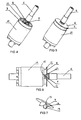
- Figures 1-7 illustrate an embodiment of the electric motor of the invention with a rotor braking device comprising a stator 2, a rotor 10 and a shaft 6 fixed to the rotor 10.
- a short-circuit ring 11 is fixed to an end of the rotor 10 and the shaft 6 extends through the short-circuit ring 11.
- a brake body 4 in the form of a circular plate rings the shaft 6 and is seated (when power is on) on the end of the short circuit ring 11.
- a friction body 7 is provided between the upperside of the brake body 4 and a front end cover 5 which is stable with respect to the stator 2.
- a spring 8 between the rotor 10 and the underside of the brake body 4 biases the brake body 4 against the friction body 7.
- a substantially cylindrical projection 12 on the underside of the brake body 4 extends coaxially within the short circuit ring 11.
- the projection 12 is provided with a recess 15 bounded by at least one beveled surface 13 which opens towards the short-circuit ring 11.
- a pin 9 is mounted radially on the shaft 6 and extends through the recess 15.
- the short-circuit ring 11 is provided with an opening 14 and the axis of the pin 9 lies in the opening 14.
- a magnetic conducting ring 3 is disposed between the rotor 10 and the brake body 4 surrounding the short-circuit ring 11 coaxially but is distant from the brake body 4.
- the magnetic conducting ring 3 exerts a force on the brake body 4 which overcomes the elastic force exerted by the spring 8.
- the brake body 4 is released and urged towards the friction body 7 by the spring 8 where its rotation is arrested and a braking force is exerted on the rotor 10.
- the rotating pin 9 is guided along the beveled surface 13 and causes the brake body 4 to move further into engagement with the friction body 7 to shorten the braking time.
Landscapes
- Engineering & Computer Science (AREA)
- Power Engineering (AREA)
- Connection Of Motors, Electrical Generators, Mechanical Devices, And The Like (AREA)
Abstract
Description
- an elongate projection on the underside of the brake body, wherein the elongate projection is provided with a recess which is bounded by at least one beveled surface; and
- a pin mounted radially on the shaft and extending through the recess.
Claims (6)
- An electric motor comprising:characterized in that the electric motor further comprises:a stator [2];a rotor [10];a front end cover [5] which is stable with respect to the stator [2];a short-circuit ring [11] fixed to an end of the rotor [10];a shaft [6] fixed to the rotor [10] and extending through the short-circuit ring [11];a brake body [4] ringing the shaft [6];a friction body [7] between the brake body [4] and the front end cover [5];a spring [8] between the rotor [10] and the brake body [4] with a tendency to bias the brake body [4] against the friction body [7],an elongate projection [12] on the underside of the brake body [4], wherein the elongate projection [12] is provided with a recess [15] which is bounded by at least one beveled surface [13]; anda pin [9] mounted radially on the shaft [6] and extending through the recess [15].
- An electric motor as claimed in claim 1 further comprising
a magnetic conducting ring [3] between the rotor [10] and the brake body [4] which surrounds the short-circuit ring [11] coaxially but is separate from the brake body [4]. - An electric motor as claimed in claim 1 or 2, wherein the short-circuit ring [3] is provided with at least one opening [14] and the axis of the pin [9] lies in the opening [14].
- An electric motor as claimed in any preceding claim wherein the brake body [4] is a substantially planar member.
- An electric motor as claimed in any preceding claim wherein the elongate projection is a substantially cylindrical projection [12].
- A brake body as defined in any preceding claim.
Applications Claiming Priority (2)
| Application Number | Priority Date | Filing Date | Title |
|---|---|---|---|
| CN02157256 | 2002-12-24 | ||
| CNA021572569A CN1510818A (en) | 2002-12-24 | 2002-12-24 | Motor with rotor brake mechanism |
Publications (2)
| Publication Number | Publication Date |
|---|---|
| EP1445849A2 true EP1445849A2 (en) | 2004-08-11 |
| EP1445849A3 EP1445849A3 (en) | 2004-11-17 |
Family
ID=32602089
Family Applications (1)
| Application Number | Title | Priority Date | Filing Date |
|---|---|---|---|
| EP03257935A Withdrawn EP1445849A3 (en) | 2002-12-24 | 2003-12-16 | Motor |
Country Status (2)
| Country | Link |
|---|---|
| EP (1) | EP1445849A3 (en) |
| CN (1) | CN1510818A (en) |
Cited By (2)
| Publication number | Priority date | Publication date | Assignee | Title |
|---|---|---|---|---|
| WO2008009552A3 (en) * | 2006-07-17 | 2008-04-03 | Siemens Ag | Rotor comprising an integrated brake for an electrical machine |
| EP2209187A3 (en) * | 2009-01-16 | 2011-12-07 | Becker-Antriebe GmbH | Tubular drive |
Families Citing this family (2)
| Publication number | Priority date | Publication date | Assignee | Title |
|---|---|---|---|---|
| CN102664485B (en) * | 2012-04-24 | 2014-01-01 | 宁波百型机械科技有限公司 | Braking structure for motor |
| CN113489270B (en) * | 2021-06-11 | 2023-06-06 | 北京精密机电控制设备研究所 | Modularized composite motor assembly |
Family Cites Families (7)
| Publication number | Priority date | Publication date | Assignee | Title |
|---|---|---|---|---|
| DE1118339B (en) * | 1958-08-28 | 1961-11-30 | Siemens Ag | Electric motor with a brake disc arranged axially displaceable on the motor shaft |
| FR1254134A (en) * | 1960-04-12 | 1961-02-17 | Braking device adaptable to electric motors | |
| DE3036091C2 (en) * | 1980-09-25 | 1986-01-30 | Hanning Elektro-Werke GmbH & Co, 4811 Oerlinghausen | Electric motor with automatic brake |
| DE3217637A1 (en) * | 1982-05-11 | 1983-11-17 | Hanning Elektro-Werke Gmbh & Co, 4800 Bielefeld | Electric motor with automatically operating brake |
| DE3407731A1 (en) * | 1984-03-02 | 1985-09-05 | Licentia Patent-Verwaltungs-Gmbh, 6000 Frankfurt | Electric motor with an automatically acting brake |
| DE3825114A1 (en) * | 1988-07-23 | 1990-01-25 | Licentia Gmbh | ELECTRIC MOTOR WITH SELF-ACTING BRAKE |
| DE3935968C2 (en) * | 1989-10-28 | 1993-11-25 | Licentia Gmbh | Electric motor with the brake acting automatically when the motor is switched off |
-
2002
- 2002-12-24 CN CNA021572569A patent/CN1510818A/en active Pending
-
2003
- 2003-12-16 EP EP03257935A patent/EP1445849A3/en not_active Withdrawn
Cited By (2)
| Publication number | Priority date | Publication date | Assignee | Title |
|---|---|---|---|---|
| WO2008009552A3 (en) * | 2006-07-17 | 2008-04-03 | Siemens Ag | Rotor comprising an integrated brake for an electrical machine |
| EP2209187A3 (en) * | 2009-01-16 | 2011-12-07 | Becker-Antriebe GmbH | Tubular drive |
Also Published As
| Publication number | Publication date |
|---|---|
| EP1445849A3 (en) | 2004-11-17 |
| CN1510818A (en) | 2004-07-07 |
Similar Documents
| Publication | Publication Date | Title |
|---|---|---|
| US4878404A (en) | Electric screwdriver | |
| CN107302275B (en) | Rotating device | |
| US11628553B2 (en) | Power tool | |
| US8653707B2 (en) | Motor having an encoder to detect rotation of a rotating body | |
| EP2124021B1 (en) | Rotary angle detecting device | |
| GB2370697A (en) | Mounting arrangement for a balance plate in a dc brushless motor | |
| JPH0785641B2 (en) | Electric motor with disk brake | |
| CN113228476A (en) | Motor | |
| EP0798709A3 (en) | Outer rotor motor | |
| KR101899799B1 (en) | Motor having resolver | |
| JP3788905B2 (en) | Vehicle lamp and drive device for rotation | |
| EP1434332A2 (en) | Motor with brake | |
| JP2006296020A (en) | Rotor of rotary electric machine and rotary electric machine | |
| JP4035436B2 (en) | Recording disk chucking mechanism and recording disk drive motor provided with the same | |
| JP3910359B2 (en) | Vehicle lamp | |
| WO2006114881A1 (en) | Electromagnetic brake device for small-sized motor | |
| KR20130010643A (en) | With built-in rotation sensor magnetic brake | |
| JP2006068593A (en) | Vibration motor | |
| KR20250023817A (en) | In-wheel motor with electronic stopping brake | |
| CA2589447C (en) | Power hand tool | |
| CN215682048U (en) | Motor with mechanical brake | |
| JP2000356228A (en) | Electromagnetic clutch | |
| JP3453035B2 (en) | Electrical component | |
| EP1443629B1 (en) | Motor | |
| CN223912370U (en) | Motor brake with pressure bearing structure and servo motor |
Legal Events
| Date | Code | Title | Description |
|---|---|---|---|
| PUAI | Public reference made under article 153(3) epc to a published international application that has entered the european phase |
Free format text: ORIGINAL CODE: 0009012 |
|
| AK | Designated contracting states |
Kind code of ref document: A2 Designated state(s): AT BE BG CH CY CZ DE DK EE ES FI FR GB GR HU IE IT LI LU MC NL PT RO SE SI SK TR |
|
| AX | Request for extension of the european patent |
Extension state: AL LT LV MK |
|
| PUAL | Search report despatched |
Free format text: ORIGINAL CODE: 0009013 |
|
| AK | Designated contracting states |
Kind code of ref document: A3 Designated state(s): AT BE BG CH CY CZ DE DK EE ES FI FR GB GR HU IE IT LI LU MC NL PT RO SE SI SK TR |
|
| AX | Request for extension of the european patent |
Extension state: AL LT LV MK |
|
| 17P | Request for examination filed |
Effective date: 20050207 |
|
| 17Q | First examination report despatched |
Effective date: 20050519 |
|
| AKX | Designation fees paid |
Designated state(s): DE FR GB IT |
|
| STAA | Information on the status of an ep patent application or granted ep patent |
Free format text: STATUS: THE APPLICATION IS DEEMED TO BE WITHDRAWN |
|
| 18D | Application deemed to be withdrawn |
Effective date: 20050930 |