EP1445542A1 - Cooking apparatus - Google Patents
Cooking apparatus Download PDFInfo
- Publication number
- EP1445542A1 EP1445542A1 EP03256985A EP03256985A EP1445542A1 EP 1445542 A1 EP1445542 A1 EP 1445542A1 EP 03256985 A EP03256985 A EP 03256985A EP 03256985 A EP03256985 A EP 03256985A EP 1445542 A1 EP1445542 A1 EP 1445542A1
- Authority
- EP
- European Patent Office
- Prior art keywords
- heater
- elastic
- cooking apparatus
- free ends
- set forth
- Prior art date
- Legal status (The legal status is an assumption and is not a legal conclusion. Google has not performed a legal analysis and makes no representation as to the accuracy of the status listed.)
- Granted
Links
Images


Classifications
-
- A—HUMAN NECESSITIES
- A47—FURNITURE; DOMESTIC ARTICLES OR APPLIANCES; COFFEE MILLS; SPICE MILLS; SUCTION CLEANERS IN GENERAL
- A47J—KITCHEN EQUIPMENT; COFFEE MILLS; SPICE MILLS; APPARATUS FOR MAKING BEVERAGES
- A47J37/00—Baking; Roasting; Grilling; Frying
- A47J37/06—Roasters; Grills; Sandwich grills
- A47J37/07—Roasting devices for outdoor use; Barbecues
- A47J37/0704—Roasting devices for outdoor use; Barbecues with horizontal fire box
- A47J37/0709—Roasting devices for outdoor use; Barbecues with horizontal fire box with electric heating elements
-
- A—HUMAN NECESSITIES
- A63—SPORTS; GAMES; AMUSEMENTS
- A63B—APPARATUS FOR PHYSICAL TRAINING, GYMNASTICS, SWIMMING, CLIMBING, OR FENCING; BALL GAMES; TRAINING EQUIPMENT
- A63B69/00—Training appliances or apparatus for special sports
- A63B69/36—Training appliances or apparatus for special sports for golf
- A63B69/3623—Training appliances or apparatus for special sports for golf for driving
- A63B69/3632—Clubs or attachments on clubs, e.g. for measuring, aligning
- A63B69/3638—Normal golf clubs with directly attached weights
-
- A—HUMAN NECESSITIES
- A63—SPORTS; GAMES; AMUSEMENTS
- A63B—APPARATUS FOR PHYSICAL TRAINING, GYMNASTICS, SWIMMING, CLIMBING, OR FENCING; BALL GAMES; TRAINING EQUIPMENT
- A63B53/00—Golf clubs
- A63B53/04—Heads
- A63B53/06—Heads adjustable
-
- A—HUMAN NECESSITIES
- A63—SPORTS; GAMES; AMUSEMENTS
- A63B—APPARATUS FOR PHYSICAL TRAINING, GYMNASTICS, SWIMMING, CLIMBING, OR FENCING; BALL GAMES; TRAINING EQUIPMENT
- A63B53/00—Golf clubs
- A63B53/14—Handles
-
- A—HUMAN NECESSITIES
- A63—SPORTS; GAMES; AMUSEMENTS
- A63B—APPARATUS FOR PHYSICAL TRAINING, GYMNASTICS, SWIMMING, CLIMBING, OR FENCING; BALL GAMES; TRAINING EQUIPMENT
- A63B60/00—Details or accessories of golf clubs, bats, rackets or the like
- A63B60/06—Handles
- A63B60/08—Handles characterised by the material
-
- A—HUMAN NECESSITIES
- A63—SPORTS; GAMES; AMUSEMENTS
- A63B—APPARATUS FOR PHYSICAL TRAINING, GYMNASTICS, SWIMMING, CLIMBING, OR FENCING; BALL GAMES; TRAINING EQUIPMENT
- A63B53/00—Golf clubs
- A63B53/04—Heads
- A63B2053/0491—Heads with added weights, e.g. changeable, replaceable
-
- A—HUMAN NECESSITIES
- A63—SPORTS; GAMES; AMUSEMENTS
- A63B—APPARATUS FOR PHYSICAL TRAINING, GYMNASTICS, SWIMMING, CLIMBING, OR FENCING; BALL GAMES; TRAINING EQUIPMENT
- A63B2102/00—Application of clubs, bats, rackets or the like to the sporting activity ; particular sports involving the use of balls and clubs, bats, rackets, or the like
- A63B2102/32—Golf
Definitions
- the present invention relates, in general, to a cooking apparatus and, more particularly, to a heater mounting unit for a cooking apparatus.
- meats or processed meat tastes best when cooked on a grill.
- a conventional cooking apparatus using the grill includes a cabinet, ceramic heaters placed in both side portions of the cabinet, a grill unit positioned on a top of the cabinet to support food to be cooked by heat thereon, and reflecting plates mounted behind the ceramic heaters to reflect heat radiated toward a position behind the ceramic heaters to the grill unit.
- Each of the ceramic heaters has a projection at a center of a rear side thereof.
- a power supply line is connected to the ceramic heater through the projection.
- the reflecting plates are each provided with a receiving hole into which the projection is inserted.
- the projection is provided with a clip groove provided in an edge thereof to receive a plate-shaped clip therein, and a leaf spring designed to be elastically disposed to fix the clip inserted into the clip groove to the reflecting plate, thus mounting the ceramic heater on the reflecting plate.
- a conventional cooking apparatus as described above is problematic in that a structure to mount the ceramic member on the reflecting plate is complicated. Thus, too much time is required to manufacture and assemble the cooking apparatus.
- the conventional cooking apparatus is generally connected to an external power supply through a back of the cabinet.
- power supply lines are positioned lengthwise through side portions of the cabinet, thus causing an assembly process and an internal construction of the cooking apparatus to be complicated.
- a cooking apparatus including a cabinet, at least one heater mounted in the cabinet, a grill unit positioned on a top of the cabinet to allow food to be cooked while being laid thereon, at least one reflecting plate mounted behind the heater to reflect heat radiated toward a position behind the heater, and at least one elastic mounting unit to mount the heater on the reflecting plate through elastic deformation thereof.
- the elastic mounting unit includes at least one pair of elastic parts and the elastic parts each have a fixed end that is fixed to the reflecting plate and a free end that is elastically movable.
- the heater is held between the free ends of the pair of elastic parts through elastic deformation of the free ends of the pair of elastic parts.
- the free ends of the elastic parts are elastically deformed to hold upper and lower portions of the heater.
- the free ends of the elastic parts have heater seats so that the upper and lower portions of the heater are inserted thereinto and seated thereon by a certain extent.
- the elastic mounting unit includes at least one elastic part, and the elastic part has a fixed end that is fixed to the reflecting plate and two free ends that are elastically movable.
- the heater is held between the free ends through elastic deformation of the free ends.
- the free ends of the elastic part are elastically deformed to hold upper and lower portions of the heater, respectively.
- the free ends of the elastic part have extended parts extended to face each other at both ends of the free ends, respectively, in order to prevent the heater from being removed from the elastic mounting unit, and the fixed end of the elastic part has a support part that is projected to support a back of the heater so as to firmly support the heater.
- the heater is provided on a back thereof with power supply terminals.
- FIG 1 is an exploded perspective view of a cooking apparatus 100, according to an embodiment of the present invention.
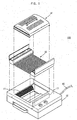
- Figure 2 is a perspective view of the cooking apparatus of Figure 1 with characteristic parts exploded therefrom.
- the cooking apparatus 100 according to the embodiment of the present invention includes a cabinet 10, two ceramic heaters 11, a grill unit 12, two reflecting plates 13, a plurality of elastic mounting units, and a cover 14.
- the ceramic heaters 11 are placed in side portions of the cabinet 10, and are each provided on a back thereof with power supply terminals 11a.
- the grill unit 12 is positioned on a top of the cabinet 10 to support food to be cooked thereon.
- the reflecting plate 13 is situated behind each of the ceramic heaters 11 to reflect heat radiated toward a position behind each of the ceramic heaters 11 to the grill unit 12 (see Figure 2).
- the elastic mounting units each include two pairs of upper and lower elastic parts 20 and 30 elastically deformed to hold upper and lower portions of the ceramic heater 11, thus mounting the ceramic heater 11 on the reflecting plate 13.
- the cover 14 surrounds a space above the grill unit 12.
- the power supply terminals 11a are positioned on the back of the ceramic heater 11 to simplify the arrangement of an external power supply line 15 connected to a back of the cooking apparatus 100.
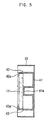
- FIG 3 is a sectional view taken along line III-III of Figure 2.
- each elastic mounting unit includes two pairs of the upper and lower elastic parts 20 and 30, and the upper and lower elastic parts 20 and 30 each have a fixed end 21 or 31 that is fixed to the reflecting plate 13 and a free end 22 or 32 that is elastically movable.
- the free ends 22 and 32 of the upper and lower elastic parts 20 and 30 are elastically deformed to hold the upper and lower portions of the ceramic heater 11.
- the free ends 22 and 32 of the upper and lower elastic parts 20 and 30 each have a heater seat 23 or 33 which the upper and lower portions of the ceramic heater 11 are respectively inserted into and seated on by a certain extent.
- the ceramic heater 11 is inserted into and seated on the heater seats 23 and 33, thus being held between the free ends 22 and 32 of the upper and lower elastic parts 20 and 30 through the elastic deformation of the free ends 22 and 32.
- Figures 4A and 4B sequentially show a method of mounting the ceramic heater 11 on the elastic mounting unit having two pairs of upper and lower elastic parts 20 and 30. Firstly, as shown in Figure 4A, a user inserts the lower portion of the ceramic heater 11 into the heater seats 33 of the lower elastic parts 30 of the elastic mounting unit, and applies a certain amount of force in a downward direction so that the upper portion of the ceramic heater 11 is not caught by the upper elastic parts 20 at the time the upper portion of the ceramic heater 11 is inserted into the heater seats 23.
- the ceramic heater 11 is mounted on the reflecting plate 13 in a state as shown in Figure 4B in a simple manner.
- FIG 5 is a sectional view of an elastic mounting unit through the use of which the ceramic heater 11 is mounted on the reflecting plate 13, according to another embodiment of the present invention.
- the elastic mounting unit includes two elastic parts, and the elastic parts each have a fixed end 41 that is fixed to the reflecting plate 13 and two free ends 42 and 43 that are elastically movable.
- the ceramic heater 11 is seated between the free ends 42 and 43 through the elastic deformation of the free ends 42 and 43.
- the free ends 42 and 43 have extended parts 42a and 43a that are extended to face each other at both ends of the free ends 42 and 43, respectively, so as to prevent the ceramic heater 11 from being removed from the elastic mounting unit.
- the fixed end 41 includes a support part 41a that is projected to support the back of the ceramic heater 11 so as to firmly support the ceramic heater 11. Accordingly, the fixed end 41 serves as the heater seat of the elastic mounting unit shown in Figure 3.
- a process of assembling the cooking apparatus is similar to that described with reference to Figures 3 and 4.
- the present invention provides a cooking apparatus, in which a heater is assembled to a cooking unit in a simple manner, thereby reducing an assembly time of the cooking apparatus and consequently improving an efficiency of production. Additionally, a heater mounting unit and a power supply line are installed in a simple manner, so that the cooking apparatus may have a simple internal construction.
Landscapes
- Health & Medical Sciences (AREA)
- General Health & Medical Sciences (AREA)
- Physical Education & Sports Medicine (AREA)
- Engineering & Computer Science (AREA)
- Food Science & Technology (AREA)
- Baking, Grill, Roasting (AREA)
- Electric Stoves And Ranges (AREA)
Abstract
Description
- The present invention relates, in general, to a cooking apparatus and, more particularly, to a heater mounting unit for a cooking apparatus.
- Generally, meats or processed meat tastes best when cooked on a grill.
- A conventional cooking apparatus using the grill includes a cabinet, ceramic heaters placed in both side portions of the cabinet, a grill unit positioned on a top of the cabinet to support food to be cooked by heat thereon, and reflecting plates mounted behind the ceramic heaters to reflect heat radiated toward a position behind the ceramic heaters to the grill unit.
- Each of the ceramic heaters has a projection at a center of a rear side thereof. A power supply line is connected to the ceramic heater through the projection. The reflecting plates are each provided with a receiving hole into which the projection is inserted. The projection is provided with a clip groove provided in an edge thereof to receive a plate-shaped clip therein, and a leaf spring designed to be elastically disposed to fix the clip inserted into the clip groove to the reflecting plate, thus mounting the ceramic heater on the reflecting plate.
- However, a conventional cooking apparatus as described above is problematic in that a structure to mount the ceramic member on the reflecting plate is complicated. Thus, too much time is required to manufacture and assemble the cooking apparatus.
- Additionally, the conventional cooking apparatus is generally connected to an external power supply through a back of the cabinet. In this case, power supply lines are positioned lengthwise through side portions of the cabinet, thus causing an assembly process and an internal construction of the cooking apparatus to be complicated.
- It is an aim of the present invention to provide a cooking apparatus provided with a heater mounting unit that mounts a heater in a simple manner and allows an internal construction of the cooking apparatus to be simple.
- Other aims and advantages of the invention will be set forth in part in the description which follows and, in part, will be obvious from the description, or may be learned by practice of the invention.
- According to the present invention there is provided an apparatus and method as set forth in the appended claims. Preferred features of the invention will be apparent from the dependent claims, and the description which follows.
- In one aspect of the present invention there is provided a cooking apparatus including a cabinet, at least one heater mounted in the cabinet, a grill unit positioned on a top of the cabinet to allow food to be cooked while being laid thereon, at least one reflecting plate mounted behind the heater to reflect heat radiated toward a position behind the heater, and at least one elastic mounting unit to mount the heater on the reflecting plate through elastic deformation thereof.
- Preferably, the elastic mounting unit includes at least one pair of elastic parts and the elastic parts each have a fixed end that is fixed to the reflecting plate and a free end that is elastically movable. The heater is held between the free ends of the pair of elastic parts through elastic deformation of the free ends of the pair of elastic parts. In this case, the free ends of the elastic parts are elastically deformed to hold upper and lower portions of the heater. Additionally, the free ends of the elastic parts have heater seats so that the upper and lower portions of the heater are inserted thereinto and seated thereon by a certain extent.
- Preferably, the elastic mounting unit includes at least one elastic part, and the elastic part has a fixed end that is fixed to the reflecting plate and two free ends that are elastically movable. The heater is held between the free ends through elastic deformation of the free ends. In this case, the free ends of the elastic part are elastically deformed to hold upper and lower portions of the heater, respectively. Additionally, the free ends of the elastic part have extended parts extended to face each other at both ends of the free ends, respectively, in order to prevent the heater from being removed from the elastic mounting unit, and the fixed end of the elastic part has a support part that is projected to support a back of the heater so as to firmly support the heater.
- Preferably, the heater is provided on a back thereof with power supply terminals.
- For a better understanding of the invention, and to show how embodiments of the same may be carried into effect, reference will now be made, by way of example, to the accompanying diagrammatic drawings in which:
- Figure 1 is an exploded perspective view of a cooking apparatus, according to an embodiment of the present invention;
- Figure 2 is a perspective view of the cooking apparatus of Figure 1 with characteristic parts exploded therefrom;
- Figure 3 is a sectional view taken along line III-III of Figure 2;
- Figures 4A and 4B show operations of a construction shown in Figure 3; and
- Figure 5 is a sectional view of a elastic mounting unit, according to another embodiment of the present invention.
-
- Figure 1 is an exploded perspective view of a
cooking apparatus 100, according to an embodiment of the present invention. Figure 2 is a perspective view of the cooking apparatus of Figure 1 with characteristic parts exploded therefrom. Referring to Figures 1 and 2, thecooking apparatus 100 according to the embodiment of the present invention includes acabinet 10, twoceramic heaters 11, agrill unit 12, two reflectingplates 13, a plurality of elastic mounting units, and acover 14. Theceramic heaters 11 are placed in side portions of thecabinet 10, and are each provided on a back thereof withpower supply terminals 11a. Thegrill unit 12 is positioned on a top of thecabinet 10 to support food to be cooked thereon. The reflectingplate 13 is situated behind each of theceramic heaters 11 to reflect heat radiated toward a position behind each of theceramic heaters 11 to the grill unit 12 (see Figure 2). The elastic mounting units each include two pairs of upper and lowerelastic parts ceramic heater 11, thus mounting theceramic heater 11 on the reflectingplate 13. Thecover 14 surrounds a space above thegrill unit 12. - In the above description, the
power supply terminals 11a are positioned on the back of theceramic heater 11 to simplify the arrangement of an externalpower supply line 15 connected to a back of thecooking apparatus 100. - Figure 3 is a sectional view taken along line III-III of Figure 2. As shown in Figure 3, each elastic mounting unit includes two pairs of the upper and lower
elastic parts elastic parts end plate 13 and afree end free ends elastic parts ceramic heater 11. As illustrated in Figure 3, thefree ends elastic parts heater seat ceramic heater 11 are respectively inserted into and seated on by a certain extent. Theceramic heater 11 is inserted into and seated on theheater seats free ends elastic parts free ends - Figures 4A and 4B sequentially show a method of mounting the
ceramic heater 11 on the elastic mounting unit having two pairs of upper and lowerelastic parts ceramic heater 11 into theheater seats 33 of the lowerelastic parts 30 of the elastic mounting unit, and applies a certain amount of force in a downward direction so that the upper portion of theceramic heater 11 is not caught by the upperelastic parts 20 at the time the upper portion of theceramic heater 11 is inserted into theheater seats 23. Thereafter, if the upper portion of theceramic heater 11 is pushed in a direction of thedeflecting plate 13, that is, in the direction shown by an arrow in Figure 4A, and the force applied to the lowerelastic parts 30 is removed, the upper portion of theceramic heater 11 is inserted into and seated on theheater seats 23 of the upperelastic parts 20. Accordingly, theceramic heater 11 is mounted on the reflectingplate 13 in a state as shown in Figure 4B in a simple manner. - Figure 5 is a sectional view of an elastic mounting unit through the use of which the
ceramic heater 11 is mounted on the reflectingplate 13, according to another embodiment of the present invention. As shown in Figure 5, the elastic mounting unit includes two elastic parts, and the elastic parts each have a fixedend 41 that is fixed to the reflectingplate 13 and twofree ends ceramic heater 11 is seated between thefree ends free ends free ends parts free ends ceramic heater 11 from being removed from the elastic mounting unit. The fixedend 41 includes asupport part 41a that is projected to support the back of theceramic heater 11 so as to firmly support theceramic heater 11. Accordingly, the fixedend 41 serves as the heater seat of the elastic mounting unit shown in Figure 3. In the case where a cooking apparatus having the elastic mounting unit as shown in Figure 5 is assembled, a process of assembling the cooking apparatus is similar to that described with reference to Figures 3 and 4. - As is apparent from the above description, the present invention provides a cooking apparatus, in which a heater is assembled to a cooking unit in a simple manner, thereby reducing an assembly time of the cooking apparatus and consequently improving an efficiency of production. Additionally, a heater mounting unit and a power supply line are installed in a simple manner, so that the cooking apparatus may have a simple internal construction.
- Although a few preferred embodiments have been shown and described, it will be appreciated by those skilled in the art that various changes and modifications might be made without departing from the scope of the invention, as defined in the appended claims.
- Attention is directed to all papers and documents which are filed concurrently with or previous to this specification in connection with this application and which are open to public inspection with this specification, and the contents of all such papers and documents are incorporated herein by reference.
- All of the features disclosed in this specification (including any accompanying claims, abstract and drawings), and/or all of the steps of any method or process so disclosed, may be combined in any combination, except combinations where at least some of such features and/or steps are mutually exclusive.
- Each feature disclosed in this specification (including any accompanying claims, abstract and drawings) may be replaced by alternative features serving the same, equivalent or similar purpose, unless expressly stated otherwise. Thus, unless expressly stated otherwise, each feature disclosed is one example only of a generic series of equivalent or similar features.
- The invention is not restricted to the details of the foregoing embodiment(s). The invention extends to any novel one, or any novel combination, of the features disclosed in this specification (including any accompanying claims, abstract and drawings), or to any novel one, or any novel combination, of the steps of any method or process so disclosed.
Claims (18)
- A cooking apparatus, comprising:a cabinet (10);at least one heater (11) mounted in the cabinet (10);a grill unit (12) positioned on a top of the cabinet (10) to allow food to be cooked while being laid thereon;at least one reflecting plate (13) mounted behind the heater (11) to reflect heat radiated toward a position behind the heater (11); andat least one elastic mounting unit (20, 30) to mount the heater (11) on the reflecting plate (13) through an elastic deformation thereof.
- The cooking apparatus as set forth in claim 1, wherein the elastic mounting unit (20, 30) comprises:at least one pair of elastic parts (20, 30), the elastic parts (20, 30) each having a fixed end (21, 31) that is fixed to the reflecting plate (13) and a free end (22, 32) that is elastically movable, the heater (11) being held between the free ends (22, 32) of the pair of elastic parts (20, 30) through an elastic deformation of the free ends (22, 32) of the pair of elastic parts (20, 30).
- The cooking apparatus as set forth in claim 2, wherein the free ends (22, 32) of the elastic parts (20, 30) are elastically deformed to hold upper and lower portions of the heater (11).
- The cooking apparatus as set forth in claim 3, wherein the free ends (22, 32) of the elastic parts (20, 30) have heater seats (23, 33) so that the upper and lower portions of the heater (11) are inserted thereinto and seated thereon by a certain extent.
- The cooking apparatus as set forth in claim 1, wherein the elastic mounting unit (20, 30) comprises:at least one elastic part, the elastic part having a fixed end (41) that is fixed to the reflecting plate (13) and two free ends (42, 43) that are elastically movable, the heater (11) being held between the free ends (42, 43) through an elastic deformation of the free ends (42, 43).
- The cooking apparatus as set forth in claim 5, wherein the free ends (42, 43) of the elastic part are elastically deformed to hold upper and lower portions of the heater (11), respectively.
- The cooking apparatus as set forth in claim 6, wherein:the free ends (42, 43) of the elastic part have extended parts (42a, 43a) extended to face each other at both ends of the free ends (42, 43), respectively, to prevent the heater (11) from being removed from the elastic mounting unit; andthe fixed end (41) of the elastic part has a support part (41a) that is projected to support a back of the heater (11) so as to firmly support the heater (11).
- The cooking apparatus as set forth in any preceding claim, wherein the heater (11) is provided on a back thereof with power supply terminals (11a).
- A cooking apparatus having a cabinet (10) and a plurality of heaters (11) mounted in the cabinet (10), comprising:a grill unit (12) located in the cabinet (10) to allow food to be cooked while being laid thereon;a plurality of reflecting plates (13) mounted behind the respective heaters (11) to reflect heat radiated toward a position behind the respective heaters (11); anda plurality of elastic mounting units (20, 30) to mount the respective heaters (11) on the respective plates through an elastic deformation thereof.
- The cooking apparatus as set forth in claim 9, wherein each of the elastic mounting units (20, 30) comprise:at least one pair of elastic parts (20, 30), the elastic parts (20, 30) each having a fixed end (21, 31) that is fixed to the respective reflecting plate (13) and a free end (22, 32) that is elastically movable, the respective heater (11) being held between the free ends (22, 32) of the pair of elastic parts (20, 30) through an elastic deformation of the free ends (22, 32) of the pair of elastic parts (20, 30).
- The cooking apparatus as set forth in claim 10, wherein the free ends (22, 32) of the elastic parts (20, 30) are elastically deformed to hold the heater (11).
- The cooking apparatus as set forth in claim 11, wherein the free ends (22, 32) of the elastic parts (20, 30) have heater seats (23, 33) so that portions of the heater (11) are inserted thereinto and seated thereon.
- The cooking apparatus as set forth in any of claims 9 to 12, wherein each of the elastic mounting unit (20, 30) comprise:at least one elastic part, the elastic part having a fixed end (41) that is fixed to the respective reflecting plate (13) and two free ends (42, 43) that are elastically movable, the respective heater (11) being held between the free ends (42, 43) through an elastic deformation of the free ends (42, 43).
- The cooking apparatus as set forth in claim 13, wherein the free ends (42, 43) of the elastic part are elastically deformed to hold portions of the heater (11), respectively.
- The cooking apparatus as set forth in claim 14, wherein:the free ends (42, 43) of the elastic part (20, 30) have extended parts (42a, 43a) extended to face each other at both ends of the free ends (42, 43), respectively, to prevent the heater (11) from being removed from the elastic mounting unit; andthe fixed end (41) of the elastic part has a support part (41a) that is projected to support a back of the heater (11) so as to firmly support the heater (11).
- The cooking apparatus as set forth in claim 13, 14 or 15, wherein the free ends (42, 43) and the fixed end (41) are integrally formed in one piece.
- The cooking apparatus as set forth in claim 15 or 16, wherein the support part (41a) is integrally formed with the free ends (42, 43) and the fixed end (41) and between pairs of each free end (42, 43) and fixed end (41).
- The cooking apparatus as set forth in any of claims 9 to 16, further comprising:power supply terminals (11a) provided behind the respective heater (11) to supply power to the heater (11).
Applications Claiming Priority (2)
| Application Number | Priority Date | Filing Date | Title |
|---|---|---|---|
| KR1020030007558A KR20040071019A (en) | 2003-02-06 | 2003-02-06 | Cooking unit |
| KR2003007558 | 2003-02-06 |
Publications (2)
| Publication Number | Publication Date |
|---|---|
| EP1445542A1 true EP1445542A1 (en) | 2004-08-11 |
| EP1445542B1 EP1445542B1 (en) | 2006-06-14 |
Family
ID=36650868
Family Applications (1)
| Application Number | Title | Priority Date | Filing Date |
|---|---|---|---|
| EP03256985A Expired - Lifetime EP1445542B1 (en) | 2003-02-06 | 2003-11-05 | Cooking apparatus |
Country Status (6)
| Country | Link |
|---|---|
| US (1) | US7312426B2 (en) |
| EP (1) | EP1445542B1 (en) |
| JP (1) | JP2004305706A (en) |
| KR (1) | KR20040071019A (en) |
| CN (1) | CN1242717C (en) |
| DE (1) | DE60306097T2 (en) |
Families Citing this family (10)
| Publication number | Priority date | Publication date | Assignee | Title |
|---|---|---|---|---|
| KR20040071021A (en) * | 2003-02-06 | 2004-08-11 | 삼성전자주식회사 | Grill and cooking unit with the same |
| US7867081B2 (en) * | 2003-12-08 | 2011-01-11 | Igt | System for join-up incentive messaging and bonusing |
| KR100588159B1 (en) | 2004-12-14 | 2006-06-09 | 삼성전자주식회사 | Grill device |
| BR112013017519A2 (en) * | 2011-02-07 | 2019-09-24 | Takita Res & Development Co Ltd | electric grill |
| US11454677B2 (en) | 2016-07-01 | 2022-09-27 | Weber-Stephen Products Llc | Wireless control and status monitoring for electric grill with current protection circuitry |
| US10551893B2 (en) | 2016-07-01 | 2020-02-04 | Weber-Stephen Products Llc | Digital power supply with wireless monitoring and control |
| US10537199B2 (en) | 2016-07-01 | 2020-01-21 | Weber-Stephen Products Llc | Digital power supply |
| US10524312B2 (en) | 2016-07-01 | 2019-12-31 | Weber-Stephen Products Llc | Electric grill with current protection circuitry |
| KR200487062Y1 (en) * | 2016-08-12 | 2018-07-31 | 주식회사 파세코 | Vertical grill cooker |
| IT201700115086A1 (en) * | 2017-10-12 | 2019-04-12 | Moretti Forni S P A | PERFECT ELECTRIC OVEN |
Citations (4)
| Publication number | Priority date | Publication date | Assignee | Title |
|---|---|---|---|---|
| US1673296A (en) * | 1926-12-27 | 1928-06-12 | Bernard O Mcmanus | Electric heater, toaster, and cooker |
| US3154004A (en) * | 1961-06-19 | 1964-10-27 | Knapp Monarch Co | Oven toaster |
| GB1096730A (en) * | 1965-06-09 | 1967-12-29 | Lazarus Benjamin De Vries | Improvements in or relating to irradiation apparatus |
| US3630970A (en) * | 1968-06-24 | 1971-12-28 | Minnesota Mining & Mfg | Resistor |
Family Cites Families (18)
| Publication number | Priority date | Publication date | Assignee | Title |
|---|---|---|---|---|
| US2030047A (en) * | 1934-05-17 | 1936-02-11 | Leo A Bonzagni | Combination broiler and toaster |
| US2778912A (en) * | 1954-07-19 | 1957-01-22 | Westinghouse Electric Corp | Toasting apparatus |
| US3074342A (en) * | 1959-03-24 | 1963-01-22 | Jack S Wachtel | Combination convertible toaster and warming oven |
| US3152242A (en) | 1963-02-25 | 1964-10-06 | Gen Electric | Cooking appliance or toaster |
| US3371659A (en) | 1966-09-14 | 1968-03-05 | Tom S. Paspalas | Throw-away portable stove |
| US4450343A (en) * | 1981-10-19 | 1984-05-22 | Dundon Gerard M | High output, long duration, quick response, radiant electrical heater |
| US4508024A (en) | 1984-04-09 | 1985-04-02 | Perkins Gary M | Indoor-outdoor convertible cooker |
| US4865864A (en) | 1985-03-27 | 1989-09-12 | Rijswijck Willem V | Air heated oven and heating method |
| US4893609A (en) | 1986-09-26 | 1990-01-16 | Teledyne Industries, Inc. | Wind-resistant outdoor heating appliance |
| FR2670274B1 (en) | 1990-12-07 | 1996-04-26 | Seb Sa | ELECTRIC COOKING APPARATUS WITH REFLECTOR. |
| US5189945A (en) | 1991-11-18 | 1993-03-02 | Hennick Donald C | Water cooled barbecue grill |
| GB9325566D0 (en) | 1993-12-14 | 1994-02-16 | Makris Andreas | Horizontal gas grill |
| US5372121A (en) | 1994-05-02 | 1994-12-13 | General Electric Company | Cooktop grate with improved stability |
| FR2724833B1 (en) | 1994-09-26 | 1997-01-17 | Seb Sa | COOKING APPARATUS AND CATALYST FORMING DEVICE PROVIDED WITH SUCH AN APPARATUS |
| US5535733A (en) | 1995-05-12 | 1996-07-16 | Pyromid, Inc. | Heat radiator for outdoor cooking unit |
| US20010039884A1 (en) | 1997-07-07 | 2001-11-15 | Alan L. Backus | Simplified device to quickly cook food |
| US6125838A (en) | 1998-12-22 | 2000-10-03 | Grills And Gadgets, Inc. | Gas grill with internal baffles for use in high wind conditions |
| US6293276B1 (en) | 2000-07-31 | 2001-09-25 | Andrea Gonzella Owens | Cook grill top lid |
-
2003
- 2003-02-06 KR KR1020030007558A patent/KR20040071019A/en not_active Withdrawn
- 2003-10-20 CN CNB2003101014554A patent/CN1242717C/en not_active Expired - Fee Related
- 2003-10-20 US US10/687,603 patent/US7312426B2/en not_active Expired - Fee Related
- 2003-11-05 EP EP03256985A patent/EP1445542B1/en not_active Expired - Lifetime
- 2003-11-05 DE DE60306097T patent/DE60306097T2/en not_active Expired - Lifetime
- 2003-11-25 JP JP2003394701A patent/JP2004305706A/en active Pending
Patent Citations (4)
| Publication number | Priority date | Publication date | Assignee | Title |
|---|---|---|---|---|
| US1673296A (en) * | 1926-12-27 | 1928-06-12 | Bernard O Mcmanus | Electric heater, toaster, and cooker |
| US3154004A (en) * | 1961-06-19 | 1964-10-27 | Knapp Monarch Co | Oven toaster |
| GB1096730A (en) * | 1965-06-09 | 1967-12-29 | Lazarus Benjamin De Vries | Improvements in or relating to irradiation apparatus |
| US3630970A (en) * | 1968-06-24 | 1971-12-28 | Minnesota Mining & Mfg | Resistor |
Also Published As
| Publication number | Publication date |
|---|---|
| JP2004305706A (en) | 2004-11-04 |
| CN1518940A (en) | 2004-08-11 |
| CN1242717C (en) | 2006-02-22 |
| DE60306097T2 (en) | 2007-01-04 |
| US20040163550A1 (en) | 2004-08-26 |
| KR20040071019A (en) | 2004-08-11 |
| DE60306097D1 (en) | 2006-07-27 |
| US7312426B2 (en) | 2007-12-25 |
| EP1445542B1 (en) | 2006-06-14 |
Similar Documents
| Publication | Publication Date | Title |
|---|---|---|
| EP1445542A1 (en) | Cooking apparatus | |
| EP1517093B1 (en) | Modular grill cooker and multipurpose cooking apparatus having the same | |
| EP2016338B1 (en) | Cooktop | |
| KR20100089083A (en) | Heating device and heat exchanger | |
| EP3539422A1 (en) | Auxiliary backrest for a chair | |
| EP1941818A3 (en) | Barbecue grill | |
| EP3705784A1 (en) | Oven burner cover screen with improved mesh configuration | |
| JP2024000089A (en) | Heater unit, heater structure, and heating cooker | |
| US5847364A (en) | Radiant heater support system | |
| JP2012022775A (en) | Cooker | |
| US9217573B2 (en) | Cook top unit for cooker | |
| KR20130011488A (en) | Electric oven | |
| AU781401B2 (en) | Shell structure for a heating appliance, and method of manufacturing heating appliance including same | |
| US6223739B1 (en) | Barbecue grill | |
| JP4566047B2 (en) | Cooker | |
| CN215127514U (en) | Electric oven | |
| US20250359666A1 (en) | Built-in system including a built-in cooking appliance and a fixing device for fixing the built-in cooking appliance to a furniture unit | |
| EP1445985A3 (en) | Electic heaters | |
| JP3533949B2 (en) | Cooking device door | |
| JP2015036608A (en) | Heating cooker | |
| CN110953637A (en) | Electric heater | |
| US20060151467A1 (en) | Cooking apparatus | |
| JP2003142250A (en) | High frequency heating equipment | |
| JP2018040549A (en) | Heat cooker | |
| JP6227929B2 (en) | Cooker |
Legal Events
| Date | Code | Title | Description |
|---|---|---|---|
| PUAI | Public reference made under article 153(3) epc to a published international application that has entered the european phase |
Free format text: ORIGINAL CODE: 0009012 |
|
| AK | Designated contracting states |
Kind code of ref document: A1 Designated state(s): AT BE BG CH CY CZ DE DK EE ES FI FR GB GR HU IE IT LI LU MC NL PT RO SE SI SK TR |
|
| AX | Request for extension of the european patent |
Extension state: AL LT LV MK |
|
| 17P | Request for examination filed |
Effective date: 20050204 |
|
| AKX | Designation fees paid |
Designated state(s): DE FR GB |
|
| RBV | Designated contracting states (corrected) |
Designated state(s): DE FR GB |
|
| GRAP | Despatch of communication of intention to grant a patent |
Free format text: ORIGINAL CODE: EPIDOSNIGR1 |
|
| GRAS | Grant fee paid |
Free format text: ORIGINAL CODE: EPIDOSNIGR3 |
|
| GRAA | (expected) grant |
Free format text: ORIGINAL CODE: 0009210 |
|
| AK | Designated contracting states |
Kind code of ref document: B1 Designated state(s): DE FR GB |
|
| REG | Reference to a national code |
Ref country code: GB Ref legal event code: FG4D |
|
| REF | Corresponds to: |
Ref document number: 60306097 Country of ref document: DE Date of ref document: 20060727 Kind code of ref document: P |
|
| ET | Fr: translation filed | ||
| PLBE | No opposition filed within time limit |
Free format text: ORIGINAL CODE: 0009261 |
|
| STAA | Information on the status of an ep patent application or granted ep patent |
Free format text: STATUS: NO OPPOSITION FILED WITHIN TIME LIMIT |
|
| 26N | No opposition filed |
Effective date: 20070315 |
|
| PGFP | Annual fee paid to national office [announced via postgrant information from national office to epo] |
Ref country code: FR Payment date: 20101123 Year of fee payment: 8 |
|
| PGFP | Annual fee paid to national office [announced via postgrant information from national office to epo] |
Ref country code: DE Payment date: 20101104 Year of fee payment: 8 |
|
| PGFP | Annual fee paid to national office [announced via postgrant information from national office to epo] |
Ref country code: GB Payment date: 20101103 Year of fee payment: 8 |
|
| GBPC | Gb: european patent ceased through non-payment of renewal fee |
Effective date: 20111105 |
|
| REG | Reference to a national code |
Ref country code: FR Ref legal event code: ST Effective date: 20120731 |
|
| REG | Reference to a national code |
Ref country code: DE Ref legal event code: R119 Ref document number: 60306097 Country of ref document: DE Effective date: 20120601 |
|
| PG25 | Lapsed in a contracting state [announced via postgrant information from national office to epo] |
Ref country code: GB Free format text: LAPSE BECAUSE OF NON-PAYMENT OF DUE FEES Effective date: 20111105 |
|
| PG25 | Lapsed in a contracting state [announced via postgrant information from national office to epo] |
Ref country code: FR Free format text: LAPSE BECAUSE OF NON-PAYMENT OF DUE FEES Effective date: 20111130 |
|
| PG25 | Lapsed in a contracting state [announced via postgrant information from national office to epo] |
Ref country code: DE Free format text: LAPSE BECAUSE OF NON-PAYMENT OF DUE FEES Effective date: 20120601 |