EP1445483A1 - Internal combustion engine starting apparatus - Google Patents
Internal combustion engine starting apparatus Download PDFInfo
- Publication number
- EP1445483A1 EP1445483A1 EP04002599A EP04002599A EP1445483A1 EP 1445483 A1 EP1445483 A1 EP 1445483A1 EP 04002599 A EP04002599 A EP 04002599A EP 04002599 A EP04002599 A EP 04002599A EP 1445483 A1 EP1445483 A1 EP 1445483A1
- Authority
- EP
- European Patent Office
- Prior art keywords
- combustion engine
- internal combustion
- motor
- lift
- pulley
- Prior art date
- Legal status (The legal status is an assumption and is not a legal conclusion. Google has not performed a legal analysis and makes no representation as to the accuracy of the status listed.)
- Withdrawn
Links
- 238000002485 combustion reaction Methods 0.000 title claims abstract description 164
- 230000005540 biological transmission Effects 0.000 claims abstract description 38
- 239000007858 starting material Substances 0.000 claims description 17
- 239000003638 chemical reducing agent Substances 0.000 claims description 13
- 238000004880 explosion Methods 0.000 claims description 13
- 238000005299 abrasion Methods 0.000 description 4
- 230000001133 acceleration Effects 0.000 description 3
- 238000010276 construction Methods 0.000 description 3
- 238000006073 displacement reaction Methods 0.000 description 3
- 238000000034 method Methods 0.000 description 3
- 230000002411 adverse Effects 0.000 description 2
- 230000001276 controlling effect Effects 0.000 description 2
- 239000000446 fuel Substances 0.000 description 2
- 230000003213 activating effect Effects 0.000 description 1
- 238000007792 addition Methods 0.000 description 1
- 238000002347 injection Methods 0.000 description 1
- 239000007924 injection Substances 0.000 description 1
- 239000000203 mixture Substances 0.000 description 1
- 230000001105 regulatory effect Effects 0.000 description 1
- 230000000717 retained effect Effects 0.000 description 1
Images


Classifications
-
- F—MECHANICAL ENGINEERING; LIGHTING; HEATING; WEAPONS; BLASTING
- F02—COMBUSTION ENGINES; HOT-GAS OR COMBUSTION-PRODUCT ENGINE PLANTS
- F02N—STARTING OF COMBUSTION ENGINES; STARTING AIDS FOR SUCH ENGINES, NOT OTHERWISE PROVIDED FOR
- F02N15/00—Other power-operated starting apparatus; Component parts, details, or accessories, not provided for in, or of interest apart from groups F02N5/00 - F02N13/00
- F02N15/02—Gearing between starting-engines and started engines; Engagement or disengagement thereof
- F02N15/022—Gearing between starting-engines and started engines; Engagement or disengagement thereof the starter comprising an intermediate clutch
- F02N15/026—Gearing between starting-engines and started engines; Engagement or disengagement thereof the starter comprising an intermediate clutch of the centrifugal type
-
- F—MECHANICAL ENGINEERING; LIGHTING; HEATING; WEAPONS; BLASTING
- F02—COMBUSTION ENGINES; HOT-GAS OR COMBUSTION-PRODUCT ENGINE PLANTS
- F02N—STARTING OF COMBUSTION ENGINES; STARTING AIDS FOR SUCH ENGINES, NOT OTHERWISE PROVIDED FOR
- F02N11/00—Starting of engines by means of electric motors
- F02N11/08—Circuits specially adapted for starting of engines
- F02N11/0814—Circuits specially adapted for starting of engines comprising means for controlling automatic idle-start-stop
- F02N11/0818—Conditions for starting or stopping the engine or for deactivating the idle-start-stop mode
-
- F—MECHANICAL ENGINEERING; LIGHTING; HEATING; WEAPONS; BLASTING
- F02—COMBUSTION ENGINES; HOT-GAS OR COMBUSTION-PRODUCT ENGINE PLANTS
- F02N—STARTING OF COMBUSTION ENGINES; STARTING AIDS FOR SUCH ENGINES, NOT OTHERWISE PROVIDED FOR
- F02N11/00—Starting of engines by means of electric motors
- F02N11/08—Circuits specially adapted for starting of engines
- F02N11/0848—Circuits specially adapted for starting of engines with means for detecting successful engine start, e.g. to stop starter actuation
-
- F—MECHANICAL ENGINEERING; LIGHTING; HEATING; WEAPONS; BLASTING
- F02—COMBUSTION ENGINES; HOT-GAS OR COMBUSTION-PRODUCT ENGINE PLANTS
- F02N—STARTING OF COMBUSTION ENGINES; STARTING AIDS FOR SUCH ENGINES, NOT OTHERWISE PROVIDED FOR
- F02N11/00—Starting of engines by means of electric motors
- F02N11/08—Circuits specially adapted for starting of engines
- F02N11/087—Details of the switching means in starting circuits, e.g. relays or electronic switches
-
- F—MECHANICAL ENGINEERING; LIGHTING; HEATING; WEAPONS; BLASTING
- F02—COMBUSTION ENGINES; HOT-GAS OR COMBUSTION-PRODUCT ENGINE PLANTS
- F02N—STARTING OF COMBUSTION ENGINES; STARTING AIDS FOR SUCH ENGINES, NOT OTHERWISE PROVIDED FOR
- F02N15/00—Other power-operated starting apparatus; Component parts, details, or accessories, not provided for in, or of interest apart from groups F02N5/00 - F02N13/00
- F02N15/02—Gearing between starting-engines and started engines; Engagement or disengagement thereof
- F02N15/04—Gearing between starting-engines and started engines; Engagement or disengagement thereof the gearing including disengaging toothed gears
- F02N15/043—Gearing between starting-engines and started engines; Engagement or disengagement thereof the gearing including disengaging toothed gears the gearing including a speed reducer
-
- F—MECHANICAL ENGINEERING; LIGHTING; HEATING; WEAPONS; BLASTING
- F02—COMBUSTION ENGINES; HOT-GAS OR COMBUSTION-PRODUCT ENGINE PLANTS
- F02N—STARTING OF COMBUSTION ENGINES; STARTING AIDS FOR SUCH ENGINES, NOT OTHERWISE PROVIDED FOR
- F02N15/00—Other power-operated starting apparatus; Component parts, details, or accessories, not provided for in, or of interest apart from groups F02N5/00 - F02N13/00
- F02N15/02—Gearing between starting-engines and started engines; Engagement or disengagement thereof
- F02N15/08—Gearing between starting-engines and started engines; Engagement or disengagement thereof the gearing being of friction type
-
- Y—GENERAL TAGGING OF NEW TECHNOLOGICAL DEVELOPMENTS; GENERAL TAGGING OF CROSS-SECTIONAL TECHNOLOGIES SPANNING OVER SEVERAL SECTIONS OF THE IPC; TECHNICAL SUBJECTS COVERED BY FORMER USPC CROSS-REFERENCE ART COLLECTIONS [XRACs] AND DIGESTS
- Y10—TECHNICAL SUBJECTS COVERED BY FORMER USPC
- Y10T—TECHNICAL SUBJECTS COVERED BY FORMER US CLASSIFICATION
- Y10T74/00—Machine element or mechanism
- Y10T74/13—Machine starters
- Y10T74/131—Automatic
- Y10T74/134—Clutch connection
Definitions
- the present invention relates to an internal combustion engine starting apparatus installed on a vehicle that runs relying on the internal combustion engine.
- the invention concerns particularly to an internal combustion engine starting apparatus suitable especially for an idle stop system that performs the temporary-stopping and re-starting of the internal combustion engine at an intersection.
- the vehicle that has an idle stop system is becoming being in practical use.
- the system stops the internal combustion engine on the vehicle when the vehicle makes a halt at an intersection and re-starts the internal combustion engine on the vehicle's re-starting.
- the vehicle that has the idle stop system is limited to such vehicle like a hybrid car that uses therein a combination of an internal combustion engine and a motor.
- the motor used in the hybrid car is generally an alternating current motor driven by a 42-volt power.
- use of an idle stop system is intended for a vehicle that is driven only by an internal combustion engine, use of a 42-volt alternating current motor is the most probable idea. This idea however has not been realized due to unacceptable strain on vehicle cost increase.
- the purpose of the present invention is to provide an internal combustion starting apparatus that emits no noise and gives lesser affection to length of service life in terms of frequency of use of the apparatus.
- the present invention may provide an internal combustion engine starting apparatus with a motor that drives said internal combustion engine; power transmission means that transmits driving power of said motor to the crankshaft of said internal combustion engine, said means being arranged between a first pulley fitted on the output shaft of said motor and a second pulley fitted on the crankshaft of said internal combustion engine; and/or a lift off type one-way cam clutch arranged between said motor and said internal combustion engine, wherein a cam is lifted off by the centrifugal force causing release of power transmission engagement between an inner element and an outer element.
- said power transmission means can be means for power-reducing transmission that reductively transmit power from said first pulley to said second pulley, and/or that said lift off type one-way cam clutch can be arranged between the output shaft of said motor and said first pulley.
- said motor can be provided with a reducer therein, said inner element of said lift off type one-way cam clutch can be integrally arranged on the output shaft of said reducer, and/or said outer element can be integrally arranged on said second pulley.
- said lift off type one-way cam clutch can be set so that said cam lifts off when the number of revolution thereof falls between such speeds that one number of revolution at which said inner combustion engine can self-perform complete explosion and/or the other number of revolution at which said internal combustion engine can run idle maintaining self-revolution.
- further said configuration can be comprised of a control means that increases a load on said internal combustion engine while the cam of said lift off type one-way cam clutch is being lifted off.
- said configuration may further comprise a relay that conveys electrical power supplied from a battery to said motor, a relay driving circuit that drives said relay, and/or an engine control unit that controls the internal combustion engine, wherein, at the time of initial starting-up, said relay is activated through operating an ignition switch to cause said motor to be driven. Further, at the time of re-starting after idle stop, said engine control unit may send a command to said relay driving circuit so that said relay is activated to cause said motor to be driven.
- said configuration may comprise a starter motor that drives the crankshaft through engagement with the ring gear fitted on the crankshaft of said internal combustion engine, a relay that feeds electrical power supplied from a battery to said motor, a relay driving circuit that drives said relay, and/or an engine control unit that controls the internal combustion engine, wherein, at the time of initial starting-up, said starter motor is driven through operating an ignition switch. Further, at the time of re-starting after idle stop, said engine control unit may send a command to said relay driving circuit so that said relay is activated to cause said motor to be driven.
- the present invention can provide an internal combustion engine starting apparatus that starts an internal combustion engine with a motor that drives said internal combustion engine and/or power transmission means that transmits driving power of said motor to the crankshaft of said internal combustion engine, wherein said power transmission means shuts off transmission of power from said internal combustion engine to said motor when the number of revolution of the crankshaft of said internal combustion engine rises beyond specified number of revolution.
- the present invention can provide an internal combustion engine starting apparatus that starts an internal combustion engine with a motor that drives said internal combustion engine, and/or power transmission means that transmits driving power of said motor to the crankshaft of said internal combustion engine, said means being arranged between a first pulley fitted on the output shaft of said motor and a second pulley fitted on the crankshaft of said internal combustion engine; a lift off type one-way cam clutch arranged between said motor and said internal combustion engine, wherein a cam is lifted off by the centrifugal force causing release of power transmission engagement between an inner element and an outer element; and/or a control means that increases a load on said internal combustion engine while the cam of said lift off type one-way cam clutch is being lifted off.
- This configuration may be suitable for a vehicle that uses a small gasoline engine having an engine displacement of 2000 cc or less for example.
- FIG. 2 An entire configuration of the internal combustion engine starting apparatus according to the present invention is explained using FIG. 2 and FIG. 2.
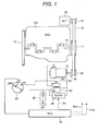
- FIG. 1 is an illustration of the entire configuration of the internal combustion engine starting apparatus according to the present invention.
- FIG. 2 is a side elevation of the apparatus in FIG. 1.
- the crank pulley 11 in the reduction side is fitted on the crankshaft 10 of the internal combustion engine 100.
- the other end of the crankshaft 10 has the ring gear 12 being fitted thereon.
- the motor pulley 22 in the over-drive side is fitted on the output shaft 21 of the direct current motor 20 via the lift off type one-way clutch 23.
- the lift off type one-way clutch 23 is a clutch that transmits the rotation of the output shaft 21 of the direct current motor 20 in one-way to the motor pulley 22 and opens the connection between the output shaft 21 and the motor pulley 22 causing them to be completely isolated each from the other when the number of revolution of the motor pulley 22 rises beyond specified number of revolution. Details of the construction of the lift off type one-way clutch 23 will be described later using FIG. 3.
- the direct current motor 20 has a reducer built-in, which is not illustrated.
- the output pulley 31 is fitted on the output shaft of the alternator 30.
- the power transmission belt 40 is arranged over the crank pulley 11 in the reduction side, the motor pulley 22 in the over-drive side, and the output pulley 31.
- the direct current motor 20 to be used is a motor driven by a 12-volt direct current voltage and having a maximum output 1.2 kW.
- the reduction ratio across the crank pulley 11 in the reduction side and the motor pulley 22 in the over-drive side is set at 2.5.
- the ignition switch 50 has three switching positions: off position (OFF), drive position (D), and start position (ST).
- OFF off position
- D drive position
- ST start position
- the engine control unit (ECU) 70 is excited by the battery 90.
- the relay 60 is excited by the battery 90 closing the contact 61 to allow the battery 90 to flow current to the direct current motor 20, which causes the direct current motor 20 to be rotated.
- a reduced power which is a power speed-reduced by the internal reducer not illustrated, is transmitted through the train formed by, and in this order, the output shaft 21 - the lift off type one-way cam clutch 23 - the power transmission belt 40 - the crank pulley 11 - the crankshaft 10 to make the cranking of the internal combustion engine 100.
- the revolution of the output shaft 21 of the direct current motor 20 is conveyed to the crankshaft 10 with a reduction rate of 1/2.5.
- the contact 61 opens causing the direct current motor 20 to stop.
- the engine control unit 70 On a vehicle stop, the engine control unit 70 outputs an engine stop signal SEST to stop the internal combustion engine 100 when the engine control unit 70 determines that the vehicle stop satisfies idle stop conditions such as the brake being pedaled and the vehicle speed being zero. Stopping the internal combustion engine 100 is achieved by bringing the signal for regulating fuel volume to be fed to the fuel injection valve, which is not illustrated, down to zero followed by stopping the ignition signal to be sent out to the igniting device, which is not illustrated.
- the engine control unit 70 After the idle stop, when the status satisfies re-starting conditions such as acceleration pedaling being active, the engine control unit 70 outputs a relay-ON signal SR to the relay driving (R-DRV) circuit 80. Then the relay driving circuit 80 excites the relay 60 causing the contact 61 to close to allow the direct current motor 20 to rotate, of which rotation cranks the internal combustion engine 100. On determination of the internal combustion engine 100 being under a complete explosion state, the ECU 70 outputs a relay-OFF signal SR to the relay driving circuit 80 making the contact 61 open to cause the direct current motor 20 to stop.
- R-DRV relay driving
- composition of the lift off type one-way clutch 23 that is used in the internal combustion engine starting apparatus according to the present invention is explained using FIG. 3.
- FIG. 3 is a fragmentary cross-sectional view to show construction of the lift off type one-way clutch 23 to be used in the internal combustion engine starting apparatus according to the present invention.
- Reference signs in the Figure that are same as those in FIG. 1 denote the same parts.
- the lift off type one-way cam clutch 23 is comprised of the cam 23 a, the outer element 23b, and the inner element 23c.
- the outer element 23b of the lift off type cam clutch 23 and the motor pulley 22 are integrated. Further, the inner element 23c and the output shaft 21 are integrated.
- the cam 23a arranged between the motor pulley 22 and the output shaft 21 lifts off by the centrifugal force.
- the lift off type one-way clutch 23 then transmits rotational power of the output shaft 21 of the direct current motor 20 to the motor pulley 22 via engagements of the cam 23a with the inner element 23c and the outer element 23b.
- the cam 23a slips preventing the rotational power from being transmitted from the outer element 23b to the inner element 23c.
- This feature is the one-way clutch.
- the cam 23a lifts off to open the transmission connection between the output shaft 21 and the motor pulley 22 causing them to be completely isolated each from the other.
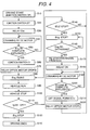
- FIG. 4 is a flow chart that shows the operation of the internal combustion engine starting apparatus according to the present invention.
- FIG. 5 is an illustration that explains the operation of the lift off type one-way clutch to be used in the internal combustion engine starting apparatus according to the present invention.
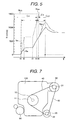
- the vertical axis denotes number of rotation (r/min) and the horizontal axis time T.
- the ignition switch 50 rests at the off (OFF) position.
- step s20 the turning of the ignition switch 50 by a driver to ST (start) position causes the contact 61 of the relay 60 to close in the step s30.
- the status of the relay 60 is ON.
- the battery 90 feeds current to the direct current motor 20 and the armature (not illustrated) of the direct current motor 20 rotates.
- the cam 23a of the lift off type one-way cam clutch 23 is under engaged state CE. Therefore, a reduced power, which is a power speed-reduced by the internal reducer not illustrated, is transmitted through the train formed by, and in this order, the output shaft 21 - the lift off type one-way cam clutch 23 - the motor pulley 22 - the power transmission belt 40 - the crank pulley 11 - the crankshaft 10 to make the cranking of the internal combustion engine 100.
- the time period between the times t1 and t2 indicates that the internal combustion engine 100 is in the cranking state.
- the driver judges whether or not the internal combustion engine 100 is in the complete explosion state and turns back the ignition switch 50 to D (drive) position in the step s60 when the engine status is under the complete explosion state.
- the time t3 in FIG. 5 shows the time when the internal combustion engine reaches the complete explosion state.
- the combustion engine 100 self-rotates relying on its self-explosion and the number of revolution Ne sharply rises.
- the number of revolution Nm of the direct current motor 20 rises at a rate of 2.5 times the number of revolution Ne of the internal combustion engine 100.
- the number of revolution Nm of the inner element 23c which is integrated with the output shaft 21 of the direct current motor 20, does not rise more than that.
- the number of revolution NL0 for lift off is set between 1000 r/min, which is a revolution 2.5 times a revolution of 400 r/min at which revolution the internal combustion engine 100 can perform the complete explosion, and 1750 r/min, which is a revolution 2.5 times a revolution of 700 r/min at which revolution the internal combustion engine 100 can run idle maintaining self-revolution (so-called idling speed of revolution).
- such number of revolution NL0 for lift off is set at 1500 r/min. Thereby, a starting failure is prevented.
- the direct current motor 20 becomes not a load to the internal combustion engine 100 resulting in a sudden release of load to the internal combustion engine 100.
- the engine control unit 70 sends a revolution-suppressing signal SND to the alternator 30 to control the alternator 30 so that the load to the internal combustion engine 100 is increased to suppress such sharp rise in the number of revolution.
- the sharp rise in the number of revolution resulted from complete explosion is suppressed after the time t5 as the solid line in FIG.
- FIG. 5 shows by the method of: providing a dummy load in the alternator 30; passing current through the dummy load using an IC regulator provided inside the alternator 30 to falsely increase the load; and thereby eliminating fluctuation of the amount of load before and after the lift off.
- IC regulator provided inside the alternator 30
- driving a compressor or lighting a headlamp triggering by the revolution-suppressing signal SND after the lift off is a probable method other than providing a dummy load in the alternator 30.
- the internal combustion engine 100 then becomes idling state.
- the vehicle begins running in the step s90 and stops in the step s100.
- the engine control unit 70 judges in the step s110 whether or not the ignition switch 50 is in the off (OFF) state.
- the state is the off (OFF) state
- the internal combustion engine is stopped in the step s120 and the driving ceases in the step s130.
- step s110 tells that the ignition switch 50 is not in the off (OFF) state
- step s140 another judgment is performed in the step s140 to examine whether idle stop conditions are satisfied or not.
- an idle stop condition a state in which vehicle speed is zero with the brake being pedaled can be one of conditions for example. If the idle stop conditions are not satisfied, the operation returns to the step s80 to continue idling.
- idle stop conditions are satisfied, the internal combustion engine 100 is stopped in the step s150.
- the judgment whether or not the internal combustion engine is to be re-started is performed in the step s160.
- a judgment criterion occurrence of acceleration pedaling for example is used as the criterion to re-start the internal combustion engine. If re-starting condition is not satisfied, the stop state of the internal combustion engine in the step s150 is retained.
- the engine control unit 70 outputs a relay ON signal SEST to the relay driving circuit 80in the step s170. Then the contact 61 closes in the step s180 causing the relay 60 to be brought to ON state and the direct current motor 20 rotates in the step s190.
- a reduced power which is a power speed-reduced by the internal reducer not illustrate, is transmitted through the train formed by, and in this order, the output shaft 21 - the lift off type one-way cam clutch 23 - the motor pulley 22 - the power transmission belt 40 - the crank pulley 11 - the crankshaft 10 to make the cranking of the internal combustion engine 100.
- the time t1 in FIG. 5 is the timing when the relay 60 becomes ON. After the time t1, the cranking of the internal combustion engine 100 begins. Succeeding states are the same states as those in previous descriptions related to FIG. 5.
- the ECU 70 determines that the internal combustion engine 100 is in the complete explosion state in the step s200, the ECU 70 outputs a relay OFF signal SEST to the relay driving circuit 80 in the step s210. Then, the contact 61 opens in the step s220 causing the direct current motor 20 to stop with the ceasing from so-called the re-starting in the idle stop.
- the lift off type one-way cam clutch 23 is arranged between the output shaft 21 of the direct current motor 20 and the motor pulley 22, arranging in any place between the crankshaft 10 of the internal combustion engine 100 and the rotor shaft of the direct current motor 20 is acceptable.
- arranging the lift off type one-way cam clutch 23 between the crankshaft 10 of the internal combustion engine 100 and the crank pulley 11, or, when the reducer is accommodated inside the direct current motor 20, arranging between the rotor shaft of the direct current motor 20 and the input shaft of the reducer is also practicable.
- the most suitable location among these places is the place, especially, between the output shaft 21 of the direct current motor 20 and said motor pulley 22 as shown in FIG. 1.
- the number of revolution for lift off is set at a value between, as stated previously, 1000 r/min and 1750 r/min, for example at 1500 r/min.
- the number of revolution for lift off might involve an error about plus/minus 100 r/min because of dimensional accuracy of the lift off type one-way cam clutch 23.
- 1500 plus/minus 100 r/min is assumable as stated above, accommodating within a planned range from 1000 r/min to 1750 r/min becomes practicable; then designing the lift off type one-way cam clutch 23 becomes easy.
- the number of revolution for lift off is set at a value between 400 r/min and 700 r/min, for example at 600 r/min, when the reduction ratio across the crank pulley 11 and the motor pulley 22 is assumed to be 2.5.
- the error in the number of revolution for lift off is assumed to be plus/minus 100 r/min and accordingly 600 plus/minus 100 r/min, it is necessary to improve accuracy of the lift off type one-way cam clutch 23 for accommodating within a planned range from 400 r/min to 700 r/min.
- the power of the direct current motor 20 is transmitted with the power transmission belt 40 to the internal combustion engine 100 and accordingly noise, which will be emitted when the pinion on the starter motor and the ring gear fitted on the crankshaft engage at the time of starting the internal combustion engine using the starter motor, is eliminated.
- the inner element 23c becomes non-contacting state with the cam 23a because the cam 23a is pulled by the centrifugal force when the number of revolution of the lift off type one-way cam clutch 23, which rotates at a number of revolution 2.5 times of the internal combustion engine 100, reaches the preset number of revolution for lift off (1500 r/min for example). Therefore, the lift off type one-way cam clutch 23 and the direct current motor 20 will not break even the internal combustion engine 100 rotates at a high speed.
- the internal combustion engine starting apparatus becomes obtainable in a easier and more economical manner compared with the case like a hybrid vehicle which uses an expensive item such as a 42-volt-driven alternating current motor.
- FIG. 6 and FIG. 7 another configuration and the operation of an internal combustion engine starting apparatus according to the present invention.
- This configuration may be suitable for a vehicle that uses a large gasoline engine having an engine displacement of 2000 cc or more and a vehicle that uses a diesel engine for example.
- FIG. 6 is an illustration of the entire configuration of the internal combustion engine starting apparatus according to the present invention.
- FIG. 7 is a side elevation of the apparatus in FIG. 6. Reference signs in the Figure that are the same as those in FIG. 1 and FIG. 2 denote the same parts.
- This configuration according to the present invention has the starter motor 95 therein in addition to the same configuration as shown in FIG. 1.
- ST start
- the internal combustion engine 100 is started by the power of the existing starter motor 95 being reduced by the ring gear 12 fitted on the crankshaft 10.
- the internal combustion engine 100 is started by the power of the direct current motor 20 being deceleratively transmitted through the train composed of the motor pulley 22 - the power transmission belt 40 - the crank pulley 11.
- the load for the initial starting is large. Therefore, use of a direct current motor having considerably large capacity is required if initial cranking by the direct current motor 20 is intended.
- the starter motor 95 is such unit that an existing vehicle already has been provided with. Then, uses of the starter motor in the initial starting and of the small size direct current motor in the re-starting in the idle stop state after warming-up can reduce the electrical power consumption.
- a 12-volt-driven motor which is an economical item, having some 1.2 kW of capacity can be used for the direct current motor 20.
- noise at the time of re-starting in the idle stop of the internal combustion engine can be eliminated because the power of the direct current motor 20 is transmitted by the power transmission belt 40 to the internal combustion engine 100.
- the lift off type one-way cam clutch 23 and the direct current motor 20 will not break even the internal combustion engine 100 rotates at a high speed because the lift off type one-way cam clutch 23 becomes non-contacting state when the number of revolution thereof reaches the preset number of revolution for lift off. Further to the above, even the internal combustion engine 100 becomes high speed rotating state, abrasion or wear in clutch components such as the cam 23a, the outer element 23b, or the inner element 23c and abrasion or wear of the brush in the direct current motor 20 are suppressed with elongated life time of the apparatus.
- the internal combustion engine starting apparatus becomes obtainable in a easier and more economical manner compared with the case like a hybrid vehicle which uses an expensive item such as a 42-volt-driven alternating current motor.
Landscapes
- Engineering & Computer Science (AREA)
- Chemical & Material Sciences (AREA)
- Combustion & Propulsion (AREA)
- Mechanical Engineering (AREA)
- General Engineering & Computer Science (AREA)
- Output Control And Ontrol Of Special Type Engine (AREA)
- Devices For Conveying Motion By Means Of Endless Flexible Members (AREA)
- Pulleys (AREA)
- One-Way And Automatic Clutches, And Combinations Of Different Clutches (AREA)
- Control Of Vehicle Engines Or Engines For Specific Uses (AREA)
Abstract
Description
- The present invention relates to an internal combustion engine starting apparatus installed on a vehicle that runs relying on the internal combustion engine. The invention concerns particularly to an internal combustion engine starting apparatus suitable especially for an idle stop system that performs the temporary-stopping and re-starting of the internal combustion engine at an intersection.
- As a recent trend, a vehicle that has an idle stop system is becoming being in practical use. The system stops the internal combustion engine on the vehicle when the vehicle makes a halt at an intersection and re-starts the internal combustion engine on the vehicle's re-starting. At present however, the vehicle that has the idle stop system is limited to such vehicle like a hybrid car that uses therein a combination of an internal combustion engine and a motor. The motor used in the hybrid car is generally an alternating current motor driven by a 42-volt power. When use of an idle stop system is intended for a vehicle that is driven only by an internal combustion engine, use of a 42-volt alternating current motor is the most probable idea. This idea however has not been realized due to unacceptable strain on vehicle cost increase.
- When, however, a plan that applies an idle stop system to a vehicle driven only by an internal combustion engine is intended, following ideas may be practicable based on the use of a motor driven by a 12-volt direct current as a starting apparatus for the internal combustion engine: 1) A use of a starter motor in a conventional configuration, and 2) A use of another start-up motor aside from the starter motor. In the first idea, which uses a starter motor, the internal combustion engine is started by the starter motor that has a pinion thereon, wherein the pinion engages, only at the time of starting, with a ring gear fitted on the crankshaft of the internal combustion engine. In the second idea, which uses another start-up motor, an arrangement is known, wherein, as the Laid-Open Japanese Patent Specification 2001-65441 for example shows, the start-up motor and the crankshaft of the internal combustion engine are linked full-time by a belt or a chain through a one-way clutch like a roller clutch and the internal combustion engine is started by making the clutch on only at the time of starting.
- However; 1) The art, wherein the internal combustion engine is re-started relying on the starter motor, brings a noise problem resulted from gear mesh sound that is emitted when the ring gear fitted on the crankshaft of the internal combustion engine engages with the pinion on the starter motor. The starter motor is used in the ordinary initial starting of an internal combustion engine. A probable gear mesh sound that will be emitted at such starting, however, would be not very intolerable to a driver because the driver is prepared to sense such noisy sound since the starting of the internal combustion engine by turning the ignition switch is the driver's intention. In an idle stop system however, the meshing sound emitted at the time of re-starting is sensed by the driver as noise. This is because of that, after making an engine stop due to halt on a red signal at an intersection, the internal combustion engine is re-started by, for example, an action for acceleration pedaling and this re-starting is hardly to be defined as a driver-initiated re-starting. Moreover, the gear meshing sound tends to be taken as intolerable noise appearing as a problem in the employing of an idle stop system since the frequency of re-starting in the idle stop system is considerably high.
- 2) The art, wherein another start-up motor is used, brings a life problem in that the length of service life of the apparatus in terms of frequency of use meets with problems such as breakage of a clutch, reduction of life of clutch mechanism, and reduction of life of the brush in a motor. These problems arise from a high-speed dragged-revolution of such clutch and motor, which are linked full-time to the internal combustion engine by a belt, caused by the internal combustion engine rotation that takes place once the engine starts. Between the motor and the internal combustion engine, a one-way clutch, which transmits the driving power from the motor in one direction, is installed. A roller clutch, used as a one-way clutch, allows transmission of reversing torque comes from the internal combustion engine adversely to the motor because of its mechanism. This adverse transmission brings a problem in that the clutch and the motor make dragged-revolution connecting to lowered life of the apparatus.
- The purpose of the present invention is to provide an internal combustion starting apparatus that emits no noise and gives lesser affection to length of service life in terms of frequency of use of the apparatus.
- (1) To attain above-mentioned purpose, the present invention may provide an internal combustion engine starting apparatus with a motor that drives said internal combustion engine; power transmission means that transmits driving power of said motor to the crankshaft of said internal combustion engine, said means being arranged between a first pulley fitted on the output shaft of said motor and a second pulley fitted on the crankshaft of said internal combustion engine; and/or a lift off type one-way cam clutch arranged between said motor and said internal combustion engine, wherein a cam is lifted off by the centrifugal force causing release of power transmission engagement between an inner element and an outer element.
- By this arrangement, gear mesh noise that the meshing of the pinion with the ring gear emits can be eliminated, and lesser affection is given to the length of service life in terms of frequency of use of the apparatus even the internal combustion engine rotates at a high speed after being started thanks to the lifting off of the cam of the one-way clutch that takes place at a pre-set number of revolution.
- (2) In the configuration mentioned in (1) above, further said power transmission means can be means for power-reducing transmission that reductively transmit power from said first pulley to said second pulley, and/or that said lift off type one-way cam clutch can be arranged between the output shaft of said motor and said first pulley.
- (3) In the configuration mentioned in (2) above, further said motor can be provided with a reducer therein, said inner element of said lift off type one-way cam clutch can be integrally arranged on the output shaft of said reducer, and/or said outer element can be integrally arranged on said second pulley.
- (4) In the configuration mentioned in (1) above, further said lift off type one-way cam clutch can be set so that said cam lifts off when the number of revolution thereof falls between such speeds that one number of revolution at which said inner combustion engine can self-perform complete explosion and/or the other number of revolution at which said internal combustion engine can run idle maintaining self-revolution.
- (5) In the configuration mentioned in (1) above, further said configuration can be comprised of a control means that increases a load on said internal combustion engine while the cam of said lift off type one-way cam clutch is being lifted off.
- (6) In the configuration mentioned in (1) above, said configuration may further comprise a relay that conveys electrical power supplied from a battery to said motor, a relay driving circuit that drives said relay, and/or an engine control unit that controls the internal combustion engine, wherein, at the time of initial starting-up, said relay is activated through operating an ignition switch to cause said motor to be driven. Further, at the time of re-starting after idle stop, said engine control unit may send a command to said relay driving circuit so that said relay is activated to cause said motor to be driven.
- (7) In the configuration mentioned in (1) above, further said configuration may comprise a starter motor that drives the crankshaft through engagement with the ring gear fitted on the crankshaft of said internal combustion engine, a relay that feeds electrical power supplied from a battery to said motor, a relay driving circuit that drives said relay, and/or an engine control unit that controls the internal combustion engine, wherein, at the time of initial starting-up, said starter motor is driven through operating an ignition switch. Further, at the time of re-starting after idle stop, said engine control unit may send a command to said relay driving circuit so that said relay is activated to cause said motor to be driven.
- (8) To attain above-mentioned purpose, the present invention can provide an internal combustion engine starting apparatus that starts an internal combustion engine with a motor that drives said internal combustion engine and/or power transmission means that transmits driving power of said motor to the crankshaft of said internal combustion engine, wherein said power transmission means shuts off transmission of power from said internal combustion engine to said motor when the number of revolution of the crankshaft of said internal combustion engine rises beyond specified number of revolution.
- By this arrangement, gear mesh noise that the meshing of a pinion with a ring gear emits can be eliminated, and lesser affection is given to the length of service life in terms of frequency of use of the apparatus even the internal combustion engine rotates at a high speed after being started thanks to the shutting off of the transmission of power from the internal combustion engine conveyed by the power transmission means.
- (9) To attain above-mentioned purpose, the present invention can provide an internal combustion engine starting apparatus that starts an internal combustion engine with a motor that drives said internal combustion engine, and/or power transmission means that transmits driving power of said motor to the crankshaft of said internal combustion engine, said means being arranged between a first pulley fitted on the output shaft of said motor and a second pulley fitted on the crankshaft of said internal combustion engine; a lift off type one-way cam clutch arranged between said motor and said internal combustion engine, wherein a cam is lifted off by the centrifugal force causing release of power transmission engagement between an inner element and an outer element; and/or a control means that increases a load on said internal combustion engine while the cam of said lift off type one-way cam clutch is being lifted off.
- By this arrangement, gear mesh noise that the meshing of a pinion with a ring gear emits can be eliminated, and lesser affection is given to the length of service life in terms of frequency of use of the apparatus even said internal combustion engine rotates at a high speed after being started preventing a revving-up at the time of lift off of the cam thanks to the shutting off of the transmission of power from the internal combustion engine conveyed by the power transmission means.
- The present invention will be understood more fully from the detailed description given hereinafter and from the accompanying drawings of the preferred embodiment of the present invention, which, however, should not be taken to be limitative to the invention, but are for explanation and understanding only.
- In the drawings:
- FIG. 1 is an illustration of an entire configuration of the internal combustion engine starting apparatus according to the present invention.
- FIG. 2 is a side elevation of the apparatus shown in FIG. 1.
- FIG. 3 is a fragmentary cross-sectional view to show construction of the lift off type one-way clutch to be used in the internal combustion engine starting apparatus according to the present invention.
- FIG. 4 is a flow chart that shows the operation of the internal combustion engine starting apparatus according to the present invention.
- FIG. 5 is an illustration that explains the operation of the lift off type one-way clutch to be used in the internal combustion engine starting apparatus according to the present invention.
- FIG. 6 is an illustration of the entire configuration of the internal combustion engine starting apparatus according to the present invention.
- FIG. 7 is a side elevation view of the apparatus in FIG. 6.
-
- The present invention will be discussed hereinafter in detail according to the present invention with reference to the accompanying drawings. In the following description, numerous specific details are set forth in order to provide a thorough understanding of the present invention. It will be obvious, however, to those skilled in the art that the present invention may be practiced without these specific details. In other instance, well-known structures are not shown in detail in order to avoid unnecessary obscurity of the present invention.
- The following explains, using FIG. 1 to FIG. 5, the configuration and the operation of an internal combustion engine starting apparatus according to the present invention. This configuration may be suitable for a vehicle that uses a small gasoline engine having an engine displacement of 2000 cc or less for example.
- Firstly, an entire configuration of the internal combustion engine starting apparatus according to the present invention is explained using FIG. 2 and FIG. 2.
- FIG. 1 is an illustration of the entire configuration of the internal combustion engine starting apparatus according to the present invention. FIG. 2 is a side elevation of the apparatus in FIG. 1.
- As shown in FIG. 1, the
crank pulley 11 in the reduction side is fitted on thecrankshaft 10 of theinternal combustion engine 100. The other end of thecrankshaft 10 has thering gear 12 being fitted thereon. Themotor pulley 22 in the over-drive side is fitted on theoutput shaft 21 of the directcurrent motor 20 via the lift off type one-way clutch 23. The lift off type one-way clutch 23 is a clutch that transmits the rotation of theoutput shaft 21 of the directcurrent motor 20 in one-way to themotor pulley 22 and opens the connection between theoutput shaft 21 and themotor pulley 22 causing them to be completely isolated each from the other when the number of revolution of themotor pulley 22 rises beyond specified number of revolution. Details of the construction of the lift off type one-way clutch 23 will be described later using FIG. 3. - The direct
current motor 20 has a reducer built-in, which is not illustrated. Theoutput pulley 31 is fitted on the output shaft of thealternator 30. As shown in FIG. 1 and FIG. 2, thepower transmission belt 40 is arranged over thecrank pulley 11 in the reduction side, themotor pulley 22 in the over-drive side, and theoutput pulley 31. When theinternal combustion engine 100 has an engine displacement of 1500 cc, the directcurrent motor 20 to be used is a motor driven by a 12-volt direct current voltage and having a maximum output 1.2 kW. The reduction ratio across thecrank pulley 11 in the reduction side and themotor pulley 22 in the over-drive side is set at 2.5. - The
ignition switch 50 has three switching positions: off position (OFF), drive position (D), and start position (ST). When a driver turns theignition switch 50 into the drive position (D), the engine control unit (ECU) 70 is excited by thebattery 90. When the driver further turns theignition switch 50 into the start position (ST), therelay 60 is excited by thebattery 90 closing thecontact 61 to allow thebattery 90 to flow current to the directcurrent motor 20, which causes the directcurrent motor 20 to be rotated. When the directcurrent motor 20 rotates, a reduced power, which is a power speed-reduced by the internal reducer not illustrated, is transmitted through the train formed by, and in this order, the output shaft 21 - the lift off type one-way cam clutch 23 - the power transmission belt 40 - the crank pulley 11 - thecrankshaft 10 to make the cranking of theinternal combustion engine 100. In this transmission, the revolution of theoutput shaft 21 of the directcurrent motor 20 is conveyed to thecrankshaft 10 with a reduction rate of 1/2.5. When the driver turns theignition switch 50 back to D (drive) position, thecontact 61 opens causing the directcurrent motor 20 to stop. - On a vehicle stop, the
engine control unit 70 outputs an engine stop signal SEST to stop theinternal combustion engine 100 when theengine control unit 70 determines that the vehicle stop satisfies idle stop conditions such as the brake being pedaled and the vehicle speed being zero. Stopping theinternal combustion engine 100 is achieved by bringing the signal for regulating fuel volume to be fed to the fuel injection valve, which is not illustrated, down to zero followed by stopping the ignition signal to be sent out to the igniting device, which is not illustrated. - After the idle stop, when the status satisfies re-starting conditions such as acceleration pedaling being active, the
engine control unit 70 outputs a relay-ON signal SR to the relay driving (R-DRV)circuit 80. Then therelay driving circuit 80 excites therelay 60 causing thecontact 61 to close to allow the directcurrent motor 20 to rotate, of which rotation cranks theinternal combustion engine 100. On determination of theinternal combustion engine 100 being under a complete explosion state, theECU 70 outputs a relay-OFF signal SR to therelay driving circuit 80 making thecontact 61 open to cause the directcurrent motor 20 to stop. - Next, composition of the lift off type one-way clutch 23 that is used in the internal combustion engine starting apparatus according to the present invention is explained using FIG. 3.
- FIG. 3 is a fragmentary cross-sectional view to show construction of the lift off type one-way clutch 23 to be used in the internal combustion engine starting apparatus according to the present invention. Reference signs in the Figure that are same as those in FIG. 1 denote the same parts.
- The lift off type one-way cam clutch 23 is comprised of the
cam 23 a, theouter element 23b, and theinner element 23c. Theouter element 23b of the lift offtype cam clutch 23 and themotor pulley 22 are integrated. Further, theinner element 23c and theoutput shaft 21 are integrated. - The
cam 23a arranged between themotor pulley 22 and theoutput shaft 21 lifts off by the centrifugal force. The lift off type one-way clutch 23 then transmits rotational power of theoutput shaft 21 of the directcurrent motor 20 to themotor pulley 22 via engagements of thecam 23a with theinner element 23c and theouter element 23b. When themotor pulley 22 rotates, thecam 23a slips preventing the rotational power from being transmitted from theouter element 23b to theinner element 23c. This feature is the one-way clutch. When the number of revolution of themotor pulley 22 rises beyond specified number of revolution thecam 23a lifts off to open the transmission connection between theoutput shaft 21 and themotor pulley 22 causing them to be completely isolated each from the other. - Next, the operation of the internal combustion engine starting apparatus according to the present invention is explained using FIG. 4 and FIG. 5.
- FIG. 4 is a flow chart that shows the operation of the internal combustion engine starting apparatus according to the present invention. FIG. 5 is an illustration that explains the operation of the lift off type one-way clutch to be used in the internal combustion engine starting apparatus according to the present invention. In FIG. 5, the vertical axis denotes number of rotation (r/min) and the horizontal axis time T.
- At the time of driving start in the step s10, the
ignition switch 50 rests at the off (OFF) position. - Next, in the step s20, the turning of the
ignition switch 50 by a driver to ST (start) position causes thecontact 61 of therelay 60 to close in the step s30. At the time t1 in FIG. 5, the status of therelay 60 is ON. - Then in the successive step s40, the
battery 90 feeds current to the directcurrent motor 20 and the armature (not illustrated) of the directcurrent motor 20 rotates. In this step, thecam 23a of the lift off type one-way cam clutch 23 is under engaged state CE. Therefore, a reduced power, which is a power speed-reduced by the internal reducer not illustrated, is transmitted through the train formed by, and in this order, the output shaft 21 - the lift off type one-way cam clutch 23 - the motor pulley 22 - the power transmission belt 40 - the crank pulley 11 - thecrankshaft 10 to make the cranking of theinternal combustion engine 100. In FIG. 5, the time period between the times t1 and t2 indicates that theinternal combustion engine 100 is in the cranking state. Also in FIG. 5, the solid line Ne shows the number of revolution of thecrankshaft 10 of theinternal combustion engine 100 and the dotted line Nm shows the number of revolution of theoutput shaft 21 of the directcurrent motor 20. Because the reduction ratio across themotor pulley 22 and thecrank pulley 11 is set at 1/2.5, Nm is given a speed determined by Nm = 2.5 x Ne. - In the step s50, the driver judges whether or not the
internal combustion engine 100 is in the complete explosion state and turns back theignition switch 50 to D (drive) position in the step s60 when the engine status is under the complete explosion state. The time t3 in FIG. 5 shows the time when the internal combustion engine reaches the complete explosion state. After the time t3, thecombustion engine 100 self-rotates relying on its self-explosion and the number of revolution Ne sharply rises. As the consequence to this, the number of revolution Nm of the directcurrent motor 20 rises at a rate of 2.5 times the number of revolution Ne of theinternal combustion engine 100. When the number of revolution of the directcurrent motor 20 at the time t4 goes up to its idling speed, the number of revolution Nm of theinner element 23c, which is integrated with theoutput shaft 21 of the directcurrent motor 20, does not rise more than that. - After the time t4 however, the number of revolution of the
outer element 23b, which is integrated with themotor pulley 22, rises to the number of revolution Nmo (shown in a two-dot chain line in FIG. 5), which is 2.5 times the number of revolution Ne of theinternal combustion engine 100, as the revolution of saidinternal combustion engine 100 rises. Then, theouter element 23b and theinner element 23c idle with the state of theinner element 23c being slipped (touching) on thecam 23a which is in contact with theouter element 23b. This means that, in FIG. 5, thecam 23a of the lift off type one-way cam clutch 23 is under engaged state CE before the time t4 but saidcam 23a of said lift off type one-way cam clutch 23 becomes a slipping state CS after the time t4. - When the numbers of revolution of the
internal combustion engine 100, themotor pulley 22, theouter element 23b, and thecam 23a Nmo rise to reach a state such that themotor pulley 22 in the over-driving side, theouter element 23b, thecam 23a rotate at a pre-set number of revolution NL0 for lift off at the time t5, thecam 23a lifts off pulled by the centrifugal force. Then, saidouter element 23b and saidinner element 23c idle with the state of theinner element 23c being under non-contact state with saidcam 23a. Consequently, thecam 23a of the lift off type one-way cam clutch 23 becomes a lifted-off state (CLO), a non-contact state. The number of revolution NL0 for lift off is set between 1000 r/min, which is a revolution 2.5 times a revolution of 400 r/min at which revolution theinternal combustion engine 100 can perform the complete explosion, and 1750 r/min, which is a revolution 2.5 times a revolution of 700 r/min at which revolution theinternal combustion engine 100 can run idle maintaining self-revolution (so-called idling speed of revolution). In the example shown in FIG. 5, such number of revolution NL0 for lift off is set at 1500 r/min. Thereby, a starting failure is prevented. - When the lift off type one-way cam clutch 23 lifts off at the time t5, the direct
current motor 20 becomes not a load to theinternal combustion engine 100 resulting in a sudden release of load to theinternal combustion engine 100. This invites a sharp rise in the number of revolution (so-called a revving-up) as the alternate long and short dash line Neu in FIG. 5 shows. Here, theengine control unit 70 sends a revolution-suppressing signal SND to thealternator 30 to control thealternator 30 so that the load to theinternal combustion engine 100 is increased to suppress such sharp rise in the number of revolution. To be more specific, the sharp rise in the number of revolution resulted from complete explosion is suppressed after the time t5 as the solid line in FIG. 5 shows by the method of: providing a dummy load in thealternator 30; passing current through the dummy load using an IC regulator provided inside thealternator 30 to falsely increase the load; and thereby eliminating fluctuation of the amount of load before and after the lift off. As another method of eliminating fluctuation of the amount of load, driving a compressor or lighting a headlamp triggering by the revolution-suppressing signal SND after the lift off is a probable method other than providing a dummy load in thealternator 30. - When the driver rests the
ignition switch 50 at the drive (D) position in the step s60, thecontact 61 opens in the step s70 causing therelay 60 to be OFF then the directcurrent motor 20 stops. On this stop, both the directcurrent motor 20 and theinner element 23c make stops but theouter element 23b alone continues rotation (idling) dragged by theinternal combustion engine 100. - In the step s80, the
internal combustion engine 100 then becomes idling state. The vehicle begins running in the step s90 and stops in the step s100. - On the vehicle stop, the
engine control unit 70 judges in the step s110 whether or not theignition switch 50 is in the off (OFF) state. When the state is the off (OFF) state, the internal combustion engine is stopped in the step s120 and the driving ceases in the step s130. - When the judgment performed in the step s110 tells that the
ignition switch 50 is not in the off (OFF) state, another judgment is performed in the step s140 to examine whether idle stop conditions are satisfied or not. As an idle stop condition, a state in which vehicle speed is zero with the brake being pedaled can be one of conditions for example. If the idle stop conditions are not satisfied, the operation returns to the step s80 to continue idling. When idle stop conditions are satisfied, theinternal combustion engine 100 is stopped in the step s150. - In the idle stop state, the judgment whether or not the internal combustion engine is to be re-started is performed in the step s160. As a judgment criterion, occurrence of acceleration pedaling for example is used as the criterion to re-start the internal combustion engine. If re-starting condition is not satisfied, the stop state of the internal combustion engine in the step s150 is retained. When re-starting condition is satisfied, the
engine control unit 70 outputs a relay ON signal SEST to the relay driving circuit 80in the step s170. Then thecontact 61 closes in the step s180 causing therelay 60 to be brought to ON state and the directcurrent motor 20 rotates in the step s190. When the directcurrent motor 20 rotates, a reduced power, which is a power speed-reduced by the internal reducer not illustrate, is transmitted through the train formed by, and in this order, the output shaft 21 - the lift off type one-way cam clutch 23 - the motor pulley 22 - the power transmission belt 40 - the crank pulley 11 - thecrankshaft 10 to make the cranking of theinternal combustion engine 100. The time t1 in FIG. 5 is the timing when therelay 60 becomes ON. After the time t1, the cranking of theinternal combustion engine 100 begins. Succeeding states are the same states as those in previous descriptions related to FIG. 5. - It is however necessary to increase the output of the direct
current motor 20 for cranking the internal combustion engine at its initial starting in the step s40 because an internal combustion engine imposes a heavy load on a cranking when the internal combustion engine is cool. Assuming that required output of the directcurrent motor 20 for such initial start is 12 V, 1.2 kW, required output of the directcurrent motor 20 for cranking to re-start the internal combustion engine after idle stop can be reduced to, for example, 0.6 kW because the internal combustion engine has been warmed up. When exciting the directcurrent motor 20 through activating therelay driving circuit 80 using theengine control unit 70, the power consumption for re-starting can be reduced by reducing the current to be passed through the directcurrent motor 20. - When the
ECU 70 determines that theinternal combustion engine 100 is in the complete explosion state in the step s200, theECU 70 outputs a relay OFF signal SEST to therelay driving circuit 80 in the step s210. Then, thecontact 61 opens in the step s220 causing the directcurrent motor 20 to stop with the ceasing from so-called the re-starting in the idle stop. - Additionally, although above explanation describes that the lift off type one-way cam clutch 23 is arranged between the
output shaft 21 of the directcurrent motor 20 and themotor pulley 22, arranging in any place between thecrankshaft 10 of theinternal combustion engine 100 and the rotor shaft of the directcurrent motor 20 is acceptable. For example, arranging the lift off type one-way cam clutch 23 between thecrankshaft 10 of theinternal combustion engine 100 and thecrank pulley 11, or, when the reducer is accommodated inside the directcurrent motor 20, arranging between the rotor shaft of the directcurrent motor 20 and the input shaft of the reducer is also practicable. The most suitable location among these places is the place, especially, between theoutput shaft 21 of the directcurrent motor 20 and saidmotor pulley 22 as shown in FIG. 1. In this case, the number of revolution for lift off is set at a value between, as stated previously, 1000 r/min and 1750 r/min, for example at 1500 r/min. In this instance, the number of revolution for lift off might involve an error about plus/minus 100 r/min because of dimensional accuracy of the lift off type one-way cam clutch 23. However, when 1500 plus/minus 100 r/min is assumable as stated above, accommodating within a planned range from 1000 r/min to 1750 r/min becomes practicable; then designing the lift off type one-way cam clutch 23 becomes easy. In contrast to the above, when the lift off type one-way cam clutch 23 is arranged between thecrankshaft 10 of theinternal combustion engine 100 and thecrank pulley 11, the number of revolution for lift off is set at a value between 400 r/min and 700 r/min, for example at 600 r/min, when the reduction ratio across thecrank pulley 11 and themotor pulley 22 is assumed to be 2.5. In this setting, when the error in the number of revolution for lift off is assumed to be plus/minus 100 r/min and accordingly 600 plus/minus 100 r/min, it is necessary to improve accuracy of the lift off type one-way cam clutch 23 for accommodating within a planned range from 400 r/min to 700 r/min. When said lift off type one-way cam clutch 23 is arranged between the rotor shaft of the directcurrent motor 20 and the input shaft of the reducer, the number of revolution for lift off is a product of the inverse number of the reduction ratio of the reducer. Although this feature makes designing a lift off type one-way cam clutch easy, the life time becomes shorter because themotor pulley 22 and the reducer are rotated by dragging by the internal combustion engine once the internal combustion engine begins complete explosion. - According to the above explained, the power of the direct
current motor 20 is transmitted with thepower transmission belt 40 to theinternal combustion engine 100 and accordingly noise, which will be emitted when the pinion on the starter motor and the ring gear fitted on the crankshaft engage at the time of starting the internal combustion engine using the starter motor, is eliminated. - Although the
internal combustion engine 100, the directcurrent motor 20, and the lift off type one-way cam clutch 23 are linked fulltime by thepower transmission belt 40, theinner element 23c becomes non-contacting state with thecam 23a because thecam 23a is pulled by the centrifugal force when the number of revolution of the lift off type one-way cam clutch 23, which rotates at a number of revolution 2.5 times of theinternal combustion engine 100, reaches the preset number of revolution for lift off (1500 r/min for example). Therefore, the lift off type one-way cam clutch 23 and the directcurrent motor 20 will not break even theinternal combustion engine 100 rotates at a high speed. Further to the above, even theinternal combustion engine 100 becomes high speed rotating state, abrasion or wear in clutch components such as thecam 23a, theouter element 23b, or theinner element 23c and abrasion or wear of a brush in the directcurrent motor 20 are suppressed with elongated life time of the apparatus. - Moreover, because of that the combined use of the direct
current motor 100, which is an economical item, with existing components (therelay 60, the rely drivingcircuit 61, thepower transmission belt 60, theECU 70, thealternator 30, thebattery 90, and the ignition switch 50) is employed, the internal combustion engine starting apparatus becomes obtainable in a easier and more economical manner compared with the case like a hybrid vehicle which uses an expensive item such as a 42-volt-driven alternating current motor. - Further, even if the sudden decrease of a load after the lift off of the
cam 23a occurs, a sharp rise in the number of revolution (so-called a revving-up) attributable to the complete explosion can be suppressed because the load on theinternal combustion engine 100 is increased by controlling thealternator 30. - The following explains, using FIG. 6 and FIG. 7, another configuration and the operation of an internal combustion engine starting apparatus according to the present invention. This configuration may be suitable for a vehicle that uses a large gasoline engine having an engine displacement of 2000 cc or more and a vehicle that uses a diesel engine for example.
- FIG. 6 is an illustration of the entire configuration of the internal combustion engine starting apparatus according to the present invention. FIG. 7 is a side elevation of the apparatus in FIG. 6. Reference signs in the Figure that are the same as those in FIG. 1 and FIG. 2 denote the same parts.
- This configuration according to the present invention has the
starter motor 95 therein in addition to the same configuration as shown in FIG. 1. Only when the internal combustion engine is started in the state wherein theignition switch 50 rests at the start (ST) position, i.e. the state so-called initial starting, theinternal combustion engine 100 is started by the power of the existingstarter motor 95 being reduced by thering gear 12 fitted on thecrankshaft 10. In contrast to this, when the internal combustion engine is started in the state wherein theignition switch 50 rests at the drive (D) position, i.e. so-called re-starting after the idle stop, theinternal combustion engine 100 is started by the power of the directcurrent motor 20 being deceleratively transmitted through the train composed of the motor pulley 22 - the power transmission belt 40 - thecrank pulley 11. - Especially in a vehicle that uses a large gasoline engine or a diesel engine, the load for the initial starting is large. Therefore, use of a direct current motor having considerably large capacity is required if initial cranking by the direct
current motor 20 is intended. However, thestarter motor 95 is such unit that an existing vehicle already has been provided with. Then, uses of the starter motor in the initial starting and of the small size direct current motor in the re-starting in the idle stop state after warming-up can reduce the electrical power consumption. In re-starting a 3000 cc gasoline engine vehicle having the idle stop system for example, a 12-volt-driven motor, which is an economical item, having some 1.2 kW of capacity can be used for the directcurrent motor 20. - According to the present invention, noise at the time of re-starting in the idle stop of the internal combustion engine can be eliminated because the power of the direct
current motor 20 is transmitted by thepower transmission belt 40 to theinternal combustion engine 100. - The lift off type one-way cam clutch 23 and the direct
current motor 20 will not break even theinternal combustion engine 100 rotates at a high speed because the lift off type one-way cam clutch 23 becomes non-contacting state when the number of revolution thereof reaches the preset number of revolution for lift off. Further to the above, even theinternal combustion engine 100 becomes high speed rotating state, abrasion or wear in clutch components such as thecam 23a, theouter element 23b, or theinner element 23c and abrasion or wear of the brush in the directcurrent motor 20 are suppressed with elongated life time of the apparatus. - Moreover, because of that the combined use of the direct
current motor 100, which is an economical item, with existing components (therelay 60, the rely drivingcircuit 61, thepower transmission belt 40, theECU 70, thealternator 30, thebattery 90, and the ignition switch 50) is employed, the internal combustion engine starting apparatus becomes obtainable in a easier and more economical manner compared with the case like a hybrid vehicle which uses an expensive item such as a 42-volt-driven alternating current motor. - Further, even if the sudden decrease of a load after the lift off of the
cam 23a occurs, a sharp rise in the number of revolution (so-called a revving-up) attributable to the complete explosion can be suppressed because the load on theinternal combustion engine 100 is increased by controlling thealternator 30. - Although the present invention has been illustrated and described with respect to exemplary embodiments thereof, it should be understood by those skilled in the art that the foregoing and various other changes, omission and additions may be made therein and thereto, without departing from the spirit and scope of the present invention. Therefore, the present invention should not be understood as limited to the specific embodiment set out above but to include all possible embodiments which can be embodied within a scope encompassed and equivalent thereof with respect to the feature set out in the appended claims.
Claims (9)
- An internal combustion engine starting apparatus that starts an internal combustion engine (100) comprising
a motor(20) that drives said internal combustion engine (100);
a power transmission means (40) that transmits driving power of said motor (20) to the crankshaft (10) of said internal combustion engine (100), said means being arranged between a first pulley (22) fitted on the output shaft (21) of said motor (20) and a second pulley (11) fitted on the crankshaft (10) of said internal combustion engine (100); and
a lift off type one-way cam clutch (23) arranged between said motor (20) and said internal combustion engine (100), wherein a cam (23a) is lifted off by the centrifugal force causing release of power transmission engagement between an inner element (23c) and an outer element (23b). - An internal combustion engine starting apparatus according to Claim 1,
wherein
said power transmission means (40) is means for power-reducing transmission that reductively transmits power from said first pulley (22) to said second pulley (11), and
said lift off type one-way cam clutch (23) is arranged between the output shaft (21) of said motor and said first pulley (22). - An internal combustion engine starting apparatus according to Claim 1 or 2,
wherein
said motor (20) is provided with a reducer therein,
said inner element (23c) of said lift off type one-way clutch (23) is integrally arranged on the output shaft (21) of said reducer, and
said outer element (23b) is integrally arranged on said second pulley (11). - An internal combustion engine starting apparatus according to at least one of the Claims 1 to 3, wherein said lift off type one-way cam clutch (23) is set so that said cam (23a) lifts off when a number of revolution thereof falls between such speeds wherein one number of revolution at which said inner combustion engine (100) can self-perform complete explosion and the other number of revolution at which said internal combustion engine (100) can run idle maintaining self-revolution.
- An internal combustion engine starting apparatus according to at least one of the Claims 1 to 4, further comprising a control means (70) that increases a load on said internal combustion engine (100) while the cam of said lift off type one-way cam clutch (23) is being lifted off.
- An internal combustion engine starting apparatus according to at least one of the Claims 1 to 5, further comprising
a relay (60) that conveys electrical power supplied from a battery (90) to said motor (20),
a relay driving circuit (80) that drives said relay (60), and
an engine control unit (70) that controls the internal combustion engine (100),
wherein,
at the time of initial starting-up, said relay (60) is activated through operating an ignition switch (50) to cause said motor (20) to be driven, and,
at the time of re-starting after idle stop, said engine control unit (70) sends a command to said relay driving circuit (80) so that said relay (60) is activated to cause said motor (20) to be driven. - An internal combustion engine starting apparatus according to at least one of the Claims 1 to 6, further comprising
a starter motor (95) that drives the crankshaft (10) of said internal combustion engine (100) through engagement with the ring gear (12) fitted on the crankshaft (10),
a relay (60) that feeds electrical power supplied from a battery (90) to the motor (20),
a relay driving circuit (80) that drives said relay (60), and
an engine control unit (70) that controls the internal combustion engine (100), wherein,
at the time of initial starting-up, said starter motor (95) is driven through operating an ignition switch (50), and,
at the time of re-starting after idle stop, said engine control unit (70) sends a command to said relay driving circuit (80) so that said relay (60) is activated to cause said motor (20) to be driven. - An internal combustion engine starting apparatus that starts an internal combustion engine (100) comprising
a motor (20) that drives said internal combustion engine (100), and
power transmission means (40) that transmits driving power of said motor (20) to the crankshaft (10) of said internal combustion engine (100), wherein said power transmission means shuts off transmission of power from said internal combustion engine (100) to said motor (20) when the number of revolution of the crankshaft (10) of said internal combustion engine (100) rises beyond specified number of revolution. - An internal combustion engine starting apparatus that starts an internal combustion engine (100) comprising
a motor (20) that drives said internal combustion engine (100), and
a power transmission means (40) that transmits driving power of said motor (20) to the crankshaft (10) of said internal combustion engine (100), said means being arranged between a first pulley (22) fitted on the output shaft (21) of said motor (20) and a second pulley (11) fitted on the crankshaft (10) of said internal combustion engine (100);
a lift off type one-way cam clutch (23) arranged between said motor (20) and said internal combustion engine (100), wherein a cam (23a) is lifted off by the centrifugal force causing release of power transmission engagement between an inner element (23c) and an outer element (23b); and
a control means (70) that increases a load on said internal combustion engine (100) while the cam (23a) of said lift off type one-way cam clutch (23) is being lifted off.
Applications Claiming Priority (2)
| Application Number | Priority Date | Filing Date | Title |
|---|---|---|---|
| JP2003029029A JP2004239159A (en) | 2003-02-06 | 2003-02-06 | Internal combustion engine starter |
| JP2003029029 | 2003-02-06 |
Publications (1)
| Publication Number | Publication Date |
|---|---|
| EP1445483A1 true EP1445483A1 (en) | 2004-08-11 |
Family
ID=32652988
Family Applications (1)
| Application Number | Title | Priority Date | Filing Date |
|---|---|---|---|
| EP04002599A Withdrawn EP1445483A1 (en) | 2003-02-06 | 2004-02-05 | Internal combustion engine starting apparatus |
Country Status (4)
| Country | Link |
|---|---|
| US (1) | US20050022770A1 (en) |
| EP (1) | EP1445483A1 (en) |
| JP (1) | JP2004239159A (en) |
| CN (1) | CN1519469A (en) |
Families Citing this family (15)
| Publication number | Priority date | Publication date | Assignee | Title |
|---|---|---|---|---|
| DE10219695A1 (en) * | 2002-05-02 | 2003-11-20 | Daimler Chrysler Ag | Drive system for a motor vehicle with an electric machine |
| FR2875556B1 (en) * | 2004-09-23 | 2009-04-17 | Valeo Equip Electr Moteur | METHOD FOR CONTROLLING A REVERSIBLE ELECTRICAL MACHINE |
| US8166945B2 (en) * | 2007-03-20 | 2012-05-01 | Litens Automotive Partnership | Starter and accessory drive system and method for hybrid drive vehicles |
| EP2312150A4 (en) * | 2008-06-10 | 2015-09-09 | Nissan Motor | Controller of internal combustion engine |
| US8833324B2 (en) * | 2010-10-01 | 2014-09-16 | Cummins Inc. | Inertia assisted engine cranking |
| KR101287862B1 (en) | 2011-01-10 | 2013-07-18 | 임명식 | apparatus for controlling engine and method for controlling the same |
| CN103597200B (en) * | 2011-09-07 | 2016-08-31 | 三菱电机株式会社 | starter for vehicle |
| DE102013209752A1 (en) * | 2012-06-13 | 2013-12-19 | Schaeffler Technologies AG & Co. KG | Method for controlling a drive train with pulley generator |
| JP6171917B2 (en) * | 2013-12-18 | 2017-08-02 | 株式会社デンソー | Engine starter |
| US9481236B2 (en) | 2014-03-13 | 2016-11-01 | GM Global Technology Operations LLC | Powertrain for a vehicle |
| US9657705B2 (en) * | 2014-03-13 | 2017-05-23 | GM Global Technology Operations LLC | Powertrain for a vehicle and an electromechanical apparatus coupleable to an engine |
| CN103939253A (en) * | 2014-05-05 | 2014-07-23 | 苏玉琴 | Belt starting device |
| DE112016002139B4 (en) * | 2015-05-12 | 2021-08-12 | Mitsubishi Electric Corporation | Engine generator, machine starting device and method for machine starting control |
| CN104989575A (en) * | 2015-06-15 | 2015-10-21 | 苏细调 | Belt starting device |
| EP3217002B1 (en) * | 2016-03-09 | 2024-08-28 | Ford Global Technologies, LLC | Method and system for providing torque-assist |
Citations (5)
| Publication number | Priority date | Publication date | Assignee | Title |
|---|---|---|---|---|
| US5905346A (en) * | 1995-05-19 | 1999-05-18 | Toyota Jidosha Kabushiki Kaisha | Power output apparatus and method of controlling the same |
| US6032632A (en) * | 1996-06-03 | 2000-03-07 | Robert Bosch Gmbh | Starting and driving unit for internal combustion engine of motor vehicle |
| DE10060835A1 (en) * | 2000-12-07 | 2002-06-13 | Ina Schaeffler Kg | Starting unit for an internal combustion engine |
| EP1270934A2 (en) * | 2001-06-22 | 2003-01-02 | Denso Corporation | Engine-starting apparatus having overrunning clutch |
| EP1293665A2 (en) * | 2001-09-13 | 2003-03-19 | Denso Corporation | Engine starter having clutch for connection to engine |
Family Cites Families (3)
| Publication number | Priority date | Publication date | Assignee | Title |
|---|---|---|---|---|
| US3750782A (en) * | 1971-10-08 | 1973-08-07 | Ford Motor Co | High speed overrunning clutch |
| US6148979A (en) * | 1998-01-20 | 2000-11-21 | Brigham Young University | Compliant overrunning clutch with centrifugal throw-out |
| US6848552B2 (en) * | 2003-04-16 | 2005-02-01 | Ntn Corporation | Starter pulley with integral clutch |
-
2003
- 2003-02-06 JP JP2003029029A patent/JP2004239159A/en not_active Withdrawn
- 2003-12-17 CN CNA2003101231221A patent/CN1519469A/en active Pending
-
2004
- 2004-02-04 US US10/771,142 patent/US20050022770A1/en not_active Abandoned
- 2004-02-05 EP EP04002599A patent/EP1445483A1/en not_active Withdrawn
Patent Citations (5)
| Publication number | Priority date | Publication date | Assignee | Title |
|---|---|---|---|---|
| US5905346A (en) * | 1995-05-19 | 1999-05-18 | Toyota Jidosha Kabushiki Kaisha | Power output apparatus and method of controlling the same |
| US6032632A (en) * | 1996-06-03 | 2000-03-07 | Robert Bosch Gmbh | Starting and driving unit for internal combustion engine of motor vehicle |
| DE10060835A1 (en) * | 2000-12-07 | 2002-06-13 | Ina Schaeffler Kg | Starting unit for an internal combustion engine |
| EP1270934A2 (en) * | 2001-06-22 | 2003-01-02 | Denso Corporation | Engine-starting apparatus having overrunning clutch |
| EP1293665A2 (en) * | 2001-09-13 | 2003-03-19 | Denso Corporation | Engine starter having clutch for connection to engine |
Also Published As
| Publication number | Publication date |
|---|---|
| CN1519469A (en) | 2004-08-11 |
| JP2004239159A (en) | 2004-08-26 |
| US20050022770A1 (en) | 2005-02-03 |
Similar Documents
| Publication | Publication Date | Title |
|---|---|---|
| EP1445483A1 (en) | Internal combustion engine starting apparatus | |
| CN101892934B (en) | System for controlling a starter for starting an internal combustion engine | |
| US6705266B2 (en) | Starter for internal combustion engine | |
| US6378479B1 (en) | Starting system for internal combustion engine | |
| JP5875664B1 (en) | Engine start control device and engine start control method | |
| US20100065001A1 (en) | Starter and Accessory Drive System And Method For Hybrid Drive Vehicles | |
| US20150096518A1 (en) | Vehicle starting system | |
| US20180135583A1 (en) | Motor generator, engine starting device, and engine start control method | |
| EP2818691A1 (en) | Engine startup device of idling-stop vehicle | |
| EP1270934B1 (en) | Engine-starting apparatus having overrunning clutch | |
| EP2895733B1 (en) | Control device of vehicle and control method of vehicle | |
| JP4003530B2 (en) | ENGINE START SYSTEM, ENGINE START METHOD, AND START CONTROL DEVICE | |
| CN100497934C (en) | Controller controlling electric machine operated to start internal combustion engine | |
| JP2000274336A (en) | Starter for internal combustion engine | |
| JP6333443B1 (en) | Engine starter | |
| JP2006348868A (en) | Engine start system | |
| JP4214812B2 (en) | Idle stop device | |
| WO2010067673A1 (en) | Roller clutch device, and starter and engine start device both using same | |
| JP4158633B2 (en) | Engine start control device for idle stop car | |
| JP2010106886A (en) | Vehicle control device | |
| JP3985621B2 (en) | ENGINE START DEVICE, START CONTROL DEVICE, START SYSTEM, AND START METHOD | |
| JPWO2016194605A1 (en) | Engine starter for vehicle | |
| JP2005188447A (en) | Engine starter | |
| CN213981015U (en) | Idling start-stop engine | |
| JP3687368B2 (en) | Vehicle start control device |
Legal Events
| Date | Code | Title | Description |
|---|---|---|---|
| PUAI | Public reference made under article 153(3) epc to a published international application that has entered the european phase |
Free format text: ORIGINAL CODE: 0009012 |
|
| AK | Designated contracting states |
Kind code of ref document: A1 Designated state(s): AT BE BG CH CY CZ DE DK EE ES FI FR GB GR HU IE IT LI LU MC NL PT RO SE SI SK TR |
|
| AX | Request for extension of the european patent |
Extension state: AL LT LV MK |
|
| 17P | Request for examination filed |
Effective date: 20041202 |
|
| AKX | Designation fees paid |
Designated state(s): DE |
|
| 17Q | First examination report despatched |
Effective date: 20050523 |
|
| RBV | Designated contracting states (corrected) |
Designated state(s): DE |
|
| STAA | Information on the status of an ep patent application or granted ep patent |
Free format text: STATUS: THE APPLICATION IS DEEMED TO BE WITHDRAWN |
|
| 18D | Application deemed to be withdrawn |
Effective date: 20051203 |