EP1445476A1 - Valve needle and metering device comprising same - Google Patents
Valve needle and metering device comprising same Download PDFInfo
- Publication number
- EP1445476A1 EP1445476A1 EP03002398A EP03002398A EP1445476A1 EP 1445476 A1 EP1445476 A1 EP 1445476A1 EP 03002398 A EP03002398 A EP 03002398A EP 03002398 A EP03002398 A EP 03002398A EP 1445476 A1 EP1445476 A1 EP 1445476A1
- Authority
- EP
- European Patent Office
- Prior art keywords
- valve needle
- guide element
- valve
- section
- cross
- Prior art date
- Legal status (The legal status is an assumption and is not a legal conclusion. Google has not performed a legal analysis and makes no representation as to the accuracy of the status listed.)
- Withdrawn
Links
Images

Classifications
-
- F—MECHANICAL ENGINEERING; LIGHTING; HEATING; WEAPONS; BLASTING
- F02—COMBUSTION ENGINES; HOT-GAS OR COMBUSTION-PRODUCT ENGINE PLANTS
- F02M—SUPPLYING COMBUSTION ENGINES IN GENERAL WITH COMBUSTIBLE MIXTURES OR CONSTITUENTS THEREOF
- F02M61/00—Fuel-injectors not provided for in groups F02M39/00 - F02M57/00 or F02M67/00
- F02M61/04—Fuel-injectors not provided for in groups F02M39/00 - F02M57/00 or F02M67/00 having valves, e.g. having a plurality of valves in series
- F02M61/08—Fuel-injectors not provided for in groups F02M39/00 - F02M57/00 or F02M67/00 having valves, e.g. having a plurality of valves in series the valves opening in direction of fuel flow
-
- F—MECHANICAL ENGINEERING; LIGHTING; HEATING; WEAPONS; BLASTING
- F02—COMBUSTION ENGINES; HOT-GAS OR COMBUSTION-PRODUCT ENGINE PLANTS
- F02M—SUPPLYING COMBUSTION ENGINES IN GENERAL WITH COMBUSTIBLE MIXTURES OR CONSTITUENTS THEREOF
- F02M61/00—Fuel-injectors not provided for in groups F02M39/00 - F02M57/00 or F02M67/00
- F02M61/04—Fuel-injectors not provided for in groups F02M39/00 - F02M57/00 or F02M67/00 having valves, e.g. having a plurality of valves in series
- F02M61/10—Other injectors with elongated valve bodies, i.e. of needle-valve type
- F02M61/12—Other injectors with elongated valve bodies, i.e. of needle-valve type characterised by the provision of guiding or centring means for valve bodies
Definitions
- the present invention relates to a valve needle for a high-pressure fuel injector, in which axial movement of the valve needle in a valve cartridge controls opening and closing of a metering opening of the injector.
- the valve needle is of the type which comprises a needle body with a cylindrical upper portion, the needle body having an end part provided with a plunger for closing the metering opening, and an elongated guide element having an upstream inlet step and a downstream outlet step and surrounding a lower portion of the needle body, the guide element providing a close sliding fit of the valve needle in the valve cartridge, and wherein the space between the cylindrical upper portion and the valve cartridge defines a fluid passage having a first cross section and the space between the guide element and the valve cartridge defines a fluid passage having a second cross section.
- the present invention further relates to a metering device for dosing pressurized fluids, particularly an injection valve for a fuel injection system in an internal combustion engine, comprising such a valve needle.
- valve needle In the production of injection valves for high-pressure direct-injection gasoline engines controlled by a piezoelectric actuator, the fit between the valve needle and the surrounding cartridge presents many geometrical and manufacturing requirements.
- the valve needle has two guide elements surrounding the needle body and providing a close sliding fit of the valve needle in the cartridge.
- the lower guide element generally has four flat surfaces separated by rounded portions that provide the sliding fit of the valve needle.
- valve needle with the features of appended claim 1.
- Advantageous embodiments of the invention are disclosed in the dependent claims 2 to 13.
- the invention also coprises a metering device for dosing pressurized fluids comprising such a valve needle according to independent claim 14.
- the size of the second cross section of the fluid passage between the guide element and the valve cartridge is about 45% or more of the size of the first cross section of the fluid passage between the cylindrical upper portion and the valve cartridge.
- the size of the second cross section is even about 60% or more of the size of the first cross section.
- the invention is based on the idea that the large transitions in the cross section between the needle and the cartridge that arise in conventional designs at the inlet and outlet steps of the guide element profile significantly contribute to the problem of circumferential spray asymmetry.
- the available flow section in the guide element section can be reduced by about 70% compared to the value above the guide element. Conversely, the available flow section can be increased by about 80% from the guide element section to the recessed section below the guide element.
- the solution according to the present invention avoids these large transitions and thereby attains a significantly improved flow stability.
- the guide element has two, three, or four longitudinally extending recessed portions separated by rounded guide portions that provide the close sliding fit of the valve needle.
- the recessed portions are formed with a concave surface.
- the recessed portions may be formed with a convex surface.
- the recess depth of the recessed portions increases from the upstream inlet step to the downstream outlet step of the guide element.
- the inlet step, the outlet step, or both steps of the guide element may advantageously be chamfered.
- the chamfer has suitably a cone angle between about 5° and about 45°, preferably between about 10° and about 30°.
- the chamfer of the inlet step and the outlet step each have a cone angle of about 15°.
- the chamfer of the inlet step has a cone angle of about 15°
- the chamfer of the outlet step has a cone angle of about 30°.
- the inlet step and/or the outlet step of the guide element may advantageously be rounded to further smoothen the transition region between the guide element and the needle body.
- the valve needle has an upper guide element for dampening pressure peaks arising from opening and closing actions of the valve needle, and a lower guide element which is formed by the elongated guide element described above.
- the valve needle has only a single guide element, which is formed by the elongated guide element described above.
- the guide element is arranged in a higher position as compared to the lower guide element of a design with two guide elements. Thereby the volume of the fuel accumulation chamber located immediately upstream of the plunger of the valve is increased.
- a metering device for dosing pressurized fluids particularly an injection valve for a fuel injection system in an internal combustion engine, comprises a housing having an end part provided with fuel admission holes leading to an outlet passage terminating with a metering opening, the lower part of the housing forming a valve cartridge surrounding the outlet passage, and an axially moveable valve needle of the type described above.
- the valve needle slides in the valve cartridge and controls opening and closing of the metering opening by its axial movement.
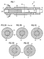
- FIG. 1 shows a schematic axial cross section of a high-pressure fuel injector valve 10 with a valve needle according to a specific embodiment of the invention.
- the needle body 12 of the valve needle comprises an upper guide element 14 and an elongated lower guide element 18, which are separated by a cylindrical upper portion 16.
- the needle body 12 further contains a recessed lower portion 20 and a plunger 22.
- valve needle slides in a fluid passage 24 formed between the needle body 12 and an inner surface of the injector cartridge 26. Pressurized fuel to be injected in an engine cylinder enters the fluid passage 24 via the fuel admission holes 28.
- Both of the guide elements 14 and 18 have the function to precisely guide the sliding movement of the valve needle in the cartridge 26.
- the upper guide element 14 has further the function to dampen the pressure peaks arising from the opening and closing action of the valve needle and heading upstream to the dynamic sealing area.
- the cross section of the fluid passage 24 varies along the longitudinal axis of the valve needle.
- the size of the cross section 30 in the upper cylindrical portion 16 is taken as a reference value and is assigned a value of 100%. All other cross sections are measured relative to the size of this cross section 30.
- the size of the cross section 32 is typically larger than in the cylindrical portion 14. In the embodiment shown, the cross section 32 has a size of 110%.
- FIG. 2(b) to 2(e) The cross section of the fluid passage 24 in the region of the lower guide element 18 taken along the line II-II of Fig. 1 is shown in Figs. 2(b) to 2(e) for various preferred embodiments of the invention.
- FIG. 2(a) shows the fluid passage cross section for a valve needle according to the prior art, where the guide element 18P has a polygonal cross section with four flat surfaces separated by rounded portions.
- the relative size of the flow cross section in this prior art design is 30%. Therefore, flowing downstream along the fluid passage 24, the fuel encounters two significant transitions in the available flow cross section: a reduction from 100% to 30%, when entering the lower guide element region, and an increase from 30% to 110%, when leaving the guide element region. These fast transitions contribute significantly to the above mentioned problem of circumferential spray asymmetry.
- the elongated guide element 18 has four longitudinally extending recessed portions separated by rounded guide portions providing the close sliding fit of the valve needle.
- the flow cross section in the guide element section is increased to a value of 66%.
- Figures 2(c) to 2(e) show other guide element designs according to preferred embodiments of the invention with increasing cannel depth of the recessed portions. The flow cross section increases from 73% for the embodiment of Fig. 2(c) to 86% for the embodiment of Fig. 2(d) and to 99% for the embodiment of Fig. 2(e).
- Figure 3 illustrates another embodiment of a valve needle according to the invention.
- Figure 3(a) shows the part of the valve needle containing the lower guide element 18.
- the guide element 18 Moving downstream from the cylindrical upper portion 16, the guide element 18 has an upstream inlet step 44 and a downstream outlet step 46, which are shown in detail in Fig. 3(b) and 3(c), respectively.
- the four rounded portions 40 provide a sliding fit between the needle and the cartridge.
- the rounded portions are separated by four concave recessed channel portions 42.
- the depth of the channels 42 may increase from the upstream inlet step 44 to the downstream outlet step 46.
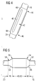
- FIG. 4 A further embodiment of a valve needle according to the invention is shown in Fig. 4.
- the elements of this embodiment correspond mostly to the elements of the embodiment of Fig. 3 with the exception that the inlet step 44 and the outlet step 46 are each provided with a chamfer 48 and 50, each with a cone angle of about 15°, to smoothen the transitions between the guide element section 18 and the adjacent needle sections 16 and 20.
- the inlet step 44, the outlet step or both steps may be rounded to further smoothen the transition.
- the rounding radii may be different for the inlet and outlet step and for the transition from the cylindrical upper portion 14 or the recessed portion 20 to the chamfer and for the transition from the chamfer to the inner section 40, 42 of the guide element.
- the upstream inlet step 44 has a chamfer 48 of 30° and rounding radii 52 and 54 of R 1 and R 1,5, respectively, and the downstream inlet step 46 has a chamfer 50 of 15° and rounding radii 56 and 58 of R 3 and R 1, respectively.
- Other practicable solutions comprise an upstream inlet step 44 that has a chamfer 48 of 15° and rounding radii 52 and 54 of R 1 and R 3, respectively, and the downstream inlet step 46 has a chamfer 50 of 15° and rounding radii 56 and 58 of R 1 and R 3, respectively.
- the upstream inlet step 44 has a chamfer 48 of 15° and rounding radii 52 and 54 of R 0,8 and R 2, respectively, and the downstream inlet steps 46 has a chamfer 50 of 15° and rounding radii 56 and 58 of R 3 and R 1, respectively.
- the inlet step 44 has a chamfer 48 of 30° and rounding radii 52 and 54 of R 0,5 and R 1,5, respectively, and the downstream inlet step 46 has a chamfer 50 of 15° and rounding radii 56 and 58 of R 3 and R 1, respectively.
Landscapes
- Engineering & Computer Science (AREA)
- Chemical & Material Sciences (AREA)
- Combustion & Propulsion (AREA)
- Mechanical Engineering (AREA)
- General Engineering & Computer Science (AREA)
- Fuel-Injection Apparatus (AREA)
Abstract
The invention relates to a valve needle for a high-pressure fuel injector, comprising a needle body (12) with a cylindrical upper portion (16), the needle body (12) having an end part provided with a plunger (22) for closing a metering opening, and an elongated guide element (18) having an upstream inlet step (44) and a downstream outlet step (46), wherein the space between the cylindrical upper portion (16) and the valve cartridge (26) defines a fluid passage (24) having a first cross section (30) and the space between the guide element (18) and the valve cartridge (26) defines a fluid passage (42) having a second cross section. According to the invention the size of the second cross section of the fluid passage (42) between the guide element (18) and the valve cartridge (26) is about 45% or more the size of the first cross section (30) of the fluid passage (24) between the cylindrical upper portion (16) and the valve cartridge (26). <IMAGE> <IMAGE>
Description
The present invention relates to a valve needle for a high-pressure
fuel injector, in which axial movement of the valve
needle in a valve cartridge controls opening and closing of a
metering opening of the injector. The valve needle is of the
type which comprises a needle body with a cylindrical upper
portion, the needle body having an end part provided with a
plunger for closing the metering opening, and an elongated
guide element having an upstream inlet step and a downstream
outlet step and surrounding a lower portion of the needle
body, the guide element providing a close sliding fit of the
valve needle in the valve cartridge, and wherein the space
between the cylindrical upper portion and the valve cartridge
defines a fluid passage having a first cross section and the
space between the guide element and the valve cartridge defines
a fluid passage having a second cross section.
The present invention further relates to a metering device
for dosing pressurized fluids, particularly an injection
valve for a fuel injection system in an internal combustion
engine, comprising such a valve needle.
In the production of injection valves for high-pressure direct-injection
gasoline engines controlled by a piezoelectric
actuator, the fit between the valve needle and the surrounding
cartridge presents many geometrical and manufacturing
requirements.
Typically, the valve needle has two guide elements surrounding
the needle body and providing a close sliding fit of the
valve needle in the cartridge. The lower guide element generally
has four flat surfaces separated by rounded portions
that provide the sliding fit of the valve needle.
In such designs the robustness of the valve needle to spray
asymmetry issues is a general issue.
It is therefore an object of the present invention to provide
a valve needle of the above mentioned type with a robust and
stable fuel path.
The above object is achieved by the valve needle with the
features of appended claim 1. Advantageous embodiments of the
invention are disclosed in the dependent claims 2 to 13.
The invention also coprises a metering device for dosing pressurized fluids comprising such a valve needle according toindependent claim 14.
The invention also coprises a metering device for dosing pressurized fluids comprising such a valve needle according to
According to the invention, in a valve needle with the features
of the preamble of claim 1, the size of the second
cross section of the fluid passage between the guide element
and the valve cartridge is about 45% or more of the size of
the first cross section of the fluid passage between the
cylindrical upper portion and the valve cartridge. Preferably,
the size of the second cross section is even about 60%
or more of the size of the first cross section.
The invention is based on the idea that the large transitions
in the cross section between the needle and the cartridge
that arise in conventional designs at the inlet and outlet
steps of the guide element profile significantly contribute
to the problem of circumferential spray asymmetry.
In conventional designs, the available flow section in the
guide element section can be reduced by about 70% compared to
the value above the guide element. Conversely, the available
flow section can be increased by about 80% from the guide
element section to the recessed section below the guide element.
The solution according to the present invention avoids
these large transitions and thereby attains a significantly
improved flow stability.
In a preferred embodiment of the invention, the guide element
has two, three, or four longitudinally extending recessed
portions separated by rounded guide portions that provide the
close sliding fit of the valve needle.
In an advantageous embodiment the recessed portions are
formed with a concave surface. Alternatively, the recessed
portions may be formed with a convex surface.
According to a further preferred embodiment of the invention,
the recess depth of the recessed portions increases from the
upstream inlet step to the downstream outlet step of the
guide element.
To provide a smooth transition between the guide element and
the needle body, the inlet step, the outlet step, or both
steps of the guide element may advantageously be chamfered.
The chamfer has suitably a cone angle between about 5° and
about 45°, preferably between about 10° and about 30°.
In a preferred embodiment, the chamfer of the inlet step and
the outlet step each have a cone angle of about 15°. According
to another preferred embodiment, the chamfer of the inlet
step has a cone angle of about 15°, and the chamfer of the
outlet step has a cone angle of about 30°.
The inlet step and/or the outlet step of the guide element
may advantageously be rounded to further smoothen the transition
region between the guide element and the needle body.
According to an especially preferred embodiment, the valve
needle has an upper guide element for dampening pressure
peaks arising from opening and closing actions of the valve
needle, and a lower guide element which is formed by the
elongated guide element described above.
In an alternative design, the valve needle has only a single
guide element, which is formed by the elongated guide element
described above. In such a design the guide element is arranged
in a higher position as compared to the lower guide
element of a design with two guide elements. Thereby the volume
of the fuel accumulation chamber located immediately
upstream of the plunger of the valve is increased.
According to the invention, a metering device for dosing
pressurized fluids, particularly an injection valve for a
fuel injection system in an internal combustion engine, comprises
a housing having an end part provided with fuel admission
holes leading to an outlet passage terminating with a
metering opening, the lower part of the housing forming a
valve cartridge surrounding the outlet passage, and an axially
moveable valve needle of the type described above. The
valve needle slides in the valve cartridge and controls opening
and closing of the metering opening by its axial movement.
In addition to the advantages mentioned above, the benefits
of the invention include
- a significant increment of the cross section between the guide element and the valve cartridge to 45% or more of the upstream flow cross section;
- reduced recirculations and a reduced stagnation line impact on the needle cartridge coupled profiles;
- a more stable path for the gasoline along the injector nozzle;
- fluid flow detachment, pressure losses and cavitation phenomena are significantly reduced or even eliminated; and
- the volume available for pressure pulsation damping in the region below, i.e. downstream of the guide element is increased.
The invention, both its construction an its method of operation
together with additional objects and advantages thereof,
will best be understood from the following description of
specific embodiments when read in connection with the accompanying
drawings, wherein
- Figure 1
- is a schematic axial cross section of the lower part of a valve needle according to a preferred embodiment of the invention, shown together with its surrounding cartridge;
- Figure 2
- shows in (a) a fluid passage cross section for a valve needle according to the prior art, and in (b) to (e) fluid passage cross sections of various preferred embodiments according to the invention, each taken along the line II-II of Fig. 1;
- Figure 3
- shows a perspective view of a valve needle according to another embodiment of the invention. In (a) the part of the valve needle containing the lower guide element is shown, and in (b) and (c) detailed views of the upstream inlet step and the downstream outlet step, respectively, are shown;
- Figure 4
- shows a perspective view of a valve needle according to a further embodiment of the invention; and
- Figure 5
- shows a schematic axial cross section of a valve needle'according to a still further embodiment of the invention.
Figure 1 shows a schematic axial cross section of a high-pressure
fuel injector valve 10 with a valve needle according
to a specific embodiment of the invention. The needle body 12
of the valve needle comprises an upper guide element 14 and
an elongated lower guide element 18, which are separated by a
cylindrical upper portion 16. The needle body 12 further contains
a recessed lower portion 20 and a plunger 22.
The valve needle slides in a fluid passage 24 formed between
the needle body 12 and an inner surface of the injector cartridge
26. Pressurized fuel to be injected in an engine cylinder
enters the fluid passage 24 via the fuel admission
holes 28. Both of the guide elements 14 and 18 have the function
to precisely guide the sliding movement of the valve
needle in the cartridge 26. The upper guide element 14 has
further the function to dampen the pressure peaks arising
from the opening and closing action of the valve needle and
heading upstream to the dynamic sealing area.
The cross section of the fluid passage 24 varies along the
longitudinal axis of the valve needle. The size of the cross
section 30 in the upper cylindrical portion 16 is taken as a
reference value and is assigned a value of 100%. All other
cross sections are measured relative to the size of this
cross section 30.
Below the lower guide element, in the recessed portion 20,
the size of the cross section 32 is typically larger than in
the cylindrical portion 14. In the embodiment shown, the
cross section 32 has a size of 110%.
The cross section of the fluid passage 24 in the region of
the lower guide element 18 taken along the line II-II of Fig.
1 is shown in Figs. 2(b) to 2(e) for various preferred embodiments
of the invention.
For comparison, Fig. 2(a) shows the fluid passage cross section
for a valve needle according to the prior art, where the
guide element 18P has a polygonal cross section with four
flat surfaces separated by rounded portions.
The relative size of the flow cross section in this prior art
design is 30%. Therefore, flowing downstream along the fluid
passage 24, the fuel encounters two significant transitions
in the available flow cross section: a reduction from 100% to
30%, when entering the lower guide element region, and an
increase from 30% to 110%, when leaving the guide element region.
These fast transitions contribute significantly to the
above mentioned problem of circumferential spray asymmetry.
It has also been observed that fluid recirculations occur in
the lower guide element section, which give rise to further
flow reductions. In addition, the stagnation line between the
needle body and the cartridge also affects the effective
cross section between the two coupled parts. The two phenomena
reduce the effective cross section in the guide element
section even below its already low geometric value.
In contrast, in the design of Fig. 2(b), the elongated guide
element 18 has four longitudinally extending recessed portions
separated by rounded guide portions providing the close
sliding fit of the valve needle. In this design, the flow
cross section in the guide element section is increased to a
value of 66%. Figures 2(c) to 2(e) show other guide element
designs according to preferred embodiments of the invention
with increasing cannel depth of the recessed portions. The
flow cross section increases from 73% for the embodiment of
Fig. 2(c) to 86% for the embodiment of Fig. 2(d) and to 99%
for the embodiment of Fig. 2(e).
Figure 3 illustrates another embodiment of a valve needle according
to the invention. Figure 3(a) shows the part of the
valve needle containing the lower guide element 18. Moving
downstream from the cylindrical upper portion 16, the guide
element 18 has an upstream inlet step 44 and a downstream
outlet step 46, which are shown in detail in Fig. 3(b) and
3(c), respectively. Again, the four rounded portions 40 provide
a sliding fit between the needle and the cartridge. The
rounded portions are separated by four concave recessed channel
portions 42. To further improve the design of Fig. 3, the
depth of the channels 42 may increase from the upstream inlet
step 44 to the downstream outlet step 46.
A further embodiment of a valve needle according to the invention
is shown in Fig. 4. The elements of this embodiment
correspond mostly to the elements of the embodiment of Fig. 3
with the exception that the inlet step 44 and the outlet step
46 are each provided with a chamfer 48 and 50, each with a
cone angle of about 15°, to smoothen the transitions between
the guide element section 18 and the adjacent needle sections
16 and 20.
In addition to being chamfered, the inlet step 44, the outlet
step or both steps may be rounded to further smoothen the
transition. The rounding radii may be different for the inlet
and outlet step and for the transition from the cylindrical
upper portion 14 or the recessed portion 20 to the chamfer
and for the transition from the chamfer to the inner section
40, 42 of the guide element.
These variations are summarized in the schematic axial cross
section of Fig. 5. In the embodiment shown, the upstream
inlet step 44 has a chamfer 48 of 30° and rounding radii 52
and 54 of R 1 and R 1,5, respectively, and the downstream
inlet step 46 has a chamfer 50 of 15° and rounding radii 56
and 58 of R 3 and R 1, respectively. Other practicable
solutions comprise an upstream inlet step 44 that has a
chamfer 48 of 15° and rounding radii 52 and 54 of R 1 and
R 3, respectively, and the downstream inlet step 46 has a
chamfer 50 of 15° and rounding radii 56 and 58 of R 1 and
R 3, respectively. In a further embodiment, the upstream
inlet step 44 has a chamfer 48 of 15° and rounding radii 52
and 54 of R 0,8 and R 2, respectively, and the downstream
inlet steps 46 has a chamfer 50 of 15° and rounding radii 56
and 58 of R 3 and R 1, respectively. In a still further
embodiment, the inlet step 44 has a chamfer 48 of 30° and
rounding radii 52 and 54 of R 0,5 and R 1,5, respectively,
and the downstream inlet step 46 has a chamfer 50 of 15° and
rounding radii 56 and 58 of R 3 and R 1, respectively.
The features disclosed in the foregoing description, in the
drawings, and in the claims may alone as well as in any possible
combination be important for the realization of the invention.
Claims (14)
- A valve needle for a high-pressure fuel injector, in which axial movement of the valve needle in a valve cartridge controls opening and closing of a metering opening of the injector, comprisingwherein the space between the cylindrical upper portion (16) and the valve cartridge (24) defines a fluid passage (24) having a first cross section (30) and the space between the guide element (18) and the valve cartridge (26) defines a fluid passage (24) having a second cross section,a needle body (12) with a cylindrical upper portion (16),the needle body (12) having an end part provided with a plunger (22) for closing the metering opening, andan elongated guide element (18) having an upstream inlet step (44) and a downstream outlet step (46) and surrounding a lower portion of the needle body (12), the guide element (18) providing a close sliding fit of the valve needle in the valve cartridge (26),
characterized in that
the size of the second cross section of the fluid passage (24) between the guide element (18) and the valve cartridge (26) is about 45% or more of the size of the first cross section (30) of the fluid passage (24) between the cylindrical upper portion (16) and the valve cartridge (26). - The valve needle according to claim 1,
characterized in that
the size of the second cross section is about 60% or more of the first cross section (30). - The valve needle according to claim 1 or 2,
characterized in that
the elongated guide element (18) has two, three, or four longitudinally extending recessed portions (42) separated by rounded guide portions (40) that provide the close sliding fit of the valve needle. - The valve needle according to claim 3,
characterized in that
the recessed portions (42) are formed with a concave surface. - The valve needle according to claim 3,
characterized in that
the recessed portions (42) are formed with a convex surface. - The valve needle according to any of claims 3 to 5,
characterized in that
the recess depth of the recessed portions (42) increases from the upstream inlet step (44) to the downstream outlet step (46) of the guide element (18). - The valve needle according to any of the preceding claims,
characterized in that
the inlet step (44) and/or the outlet step (46) of the guide element (18) is chamfered (48, 50) to provide a smooth transition to the needle body (12). - The valve needle according to claim 7,
characterized in that
the chamfer (48, 50) has a cone angle between about 5° and about 45°, preferably between about 10° and about 30°. - The valve needle according to claim 7 or 8,
characterized in that
the chamfer (48, 50) of the inlet step (44) and the outlet step (46) each have a cone angle of about 15°. - The valve needle according to claim 7 or 8,
characterized in that
the chamfer (48) of the inlet step (44) has a cone angle of about 15°, and the chamfer (50) of the outlet step (46) has a cone angle of about 30°. - The valve needle according to any of the preceding claims,
characterized in that
the inlet step (44) and/or the outlet step (44) of the guide element (18) is rounded. - The valve needle according to any of the preceding claims,
characterized in that
the valve needle has an upper guide element (14) for dampening pressure peaks arising from opening and closing actions of the valve needle, and a lower guide element formed by the elongated guide element (18). - The valve needle according to any of claims 1 to 11,
characterized in that
the valve needle has a single guide element formed by the elongated guide element (18). - A metering device for dosing pressurized fluids, particularly an injection valve for a fuel injection system in an internal combustion engine, comprisinga housing having an end part provided with fuel admission holes (28) leading to a fluid passage (24) terminating with a metering opening, the lower part of the housing forming a valve cartridge (26) surrounding the fluid passage (24), andan axially moveable valve needle according to any of the preceding claims, sliding in the valve cartridge (26) and controlling opening and closing of the metering opening by its axial movement.
Priority Applications (1)
| Application Number | Priority Date | Filing Date | Title |
|---|---|---|---|
| EP03002398A EP1445476A1 (en) | 2003-02-04 | 2003-02-04 | Valve needle and metering device comprising same |
Applications Claiming Priority (1)
| Application Number | Priority Date | Filing Date | Title |
|---|---|---|---|
| EP03002398A EP1445476A1 (en) | 2003-02-04 | 2003-02-04 | Valve needle and metering device comprising same |
Publications (1)
| Publication Number | Publication Date |
|---|---|
| EP1445476A1 true EP1445476A1 (en) | 2004-08-11 |
Family
ID=32605311
Family Applications (1)
| Application Number | Title | Priority Date | Filing Date |
|---|---|---|---|
| EP03002398A Withdrawn EP1445476A1 (en) | 2003-02-04 | 2003-02-04 | Valve needle and metering device comprising same |
Country Status (1)
| Country | Link |
|---|---|
| EP (1) | EP1445476A1 (en) |
Cited By (3)
| Publication number | Priority date | Publication date | Assignee | Title |
|---|---|---|---|---|
| EP2405127A1 (en) * | 2010-07-07 | 2012-01-11 | Wärtsilä Switzerland Ltd. | A fuel injector for internal combustion engines |
| EP2924275A1 (en) * | 2014-03-25 | 2015-09-30 | Liebherr Machines Bulle SA | Injector with increased flow cross section |
| CN105386895A (en) * | 2014-09-03 | 2016-03-09 | 罗伯特·博世有限公司 | Gaseous fuel gas injector with universal supporting member |
Citations (9)
| Publication number | Priority date | Publication date | Assignee | Title |
|---|---|---|---|---|
| DE2542727A1 (en) * | 1975-09-25 | 1977-03-31 | Bosch Gmbh Robert | IC engine direct injection fuel nozzle - has valve needle with adjustable restrictor |
| US4519547A (en) * | 1982-07-06 | 1985-05-28 | Robert Bosch Gmbh | Injection valve |
| JPH04311671A (en) * | 1991-04-08 | 1992-11-04 | Zexel Corp | Fuel injection valve |
| JPH04342869A (en) * | 1991-05-17 | 1992-11-30 | Nissan Motor Co Ltd | Fuel injection nozzle |
| DE4128821A1 (en) * | 1991-08-30 | 1993-03-04 | Bosch Gmbh Robert | ELECTROMAGNETICALLY OPERATED INJECTION VALVE |
| US5211340A (en) * | 1991-08-27 | 1993-05-18 | Zexel Corporation | Fuel injector |
| JPH10122093A (en) * | 1996-10-21 | 1998-05-12 | Daihatsu Motor Co Ltd | Fuel injection nozzle for diesel engine |
| DE19853266A1 (en) * | 1998-11-18 | 2000-05-31 | Siemens Ag | Fuel injection valve for IC engine |
| EP1026393A2 (en) * | 1999-02-05 | 2000-08-09 | Siemens Aktiengesellschaft | Injector for the injection system of an internal combustion engine |
-
2003
- 2003-02-04 EP EP03002398A patent/EP1445476A1/en not_active Withdrawn
Patent Citations (9)
| Publication number | Priority date | Publication date | Assignee | Title |
|---|---|---|---|---|
| DE2542727A1 (en) * | 1975-09-25 | 1977-03-31 | Bosch Gmbh Robert | IC engine direct injection fuel nozzle - has valve needle with adjustable restrictor |
| US4519547A (en) * | 1982-07-06 | 1985-05-28 | Robert Bosch Gmbh | Injection valve |
| JPH04311671A (en) * | 1991-04-08 | 1992-11-04 | Zexel Corp | Fuel injection valve |
| JPH04342869A (en) * | 1991-05-17 | 1992-11-30 | Nissan Motor Co Ltd | Fuel injection nozzle |
| US5211340A (en) * | 1991-08-27 | 1993-05-18 | Zexel Corporation | Fuel injector |
| DE4128821A1 (en) * | 1991-08-30 | 1993-03-04 | Bosch Gmbh Robert | ELECTROMAGNETICALLY OPERATED INJECTION VALVE |
| JPH10122093A (en) * | 1996-10-21 | 1998-05-12 | Daihatsu Motor Co Ltd | Fuel injection nozzle for diesel engine |
| DE19853266A1 (en) * | 1998-11-18 | 2000-05-31 | Siemens Ag | Fuel injection valve for IC engine |
| EP1026393A2 (en) * | 1999-02-05 | 2000-08-09 | Siemens Aktiengesellschaft | Injector for the injection system of an internal combustion engine |
Non-Patent Citations (3)
| Title |
|---|
| PATENT ABSTRACTS OF JAPAN vol. 017, no. 133 (M - 1383) 19 March 1993 (1993-03-19) * |
| PATENT ABSTRACTS OF JAPAN vol. 017, no. 198 (M - 1398) 19 April 1993 (1993-04-19) * |
| PATENT ABSTRACTS OF JAPAN vol. 1998, no. 10 31 August 1998 (1998-08-31) * |
Cited By (4)
| Publication number | Priority date | Publication date | Assignee | Title |
|---|---|---|---|---|
| EP2405127A1 (en) * | 2010-07-07 | 2012-01-11 | Wärtsilä Switzerland Ltd. | A fuel injector for internal combustion engines |
| EP2924275A1 (en) * | 2014-03-25 | 2015-09-30 | Liebherr Machines Bulle SA | Injector with increased flow cross section |
| CN105386895A (en) * | 2014-09-03 | 2016-03-09 | 罗伯特·博世有限公司 | Gaseous fuel gas injector with universal supporting member |
| CN105386895B (en) * | 2014-09-03 | 2019-11-19 | 罗伯特·博世有限公司 | Gas injector for gaseous fuel with universal bearing |
Similar Documents
| Publication | Publication Date | Title |
|---|---|---|
| US10982639B2 (en) | Fuel injector | |
| US8602328B2 (en) | Fuel injection device | |
| EP1811165B1 (en) | Common rail having orifice | |
| EP1965070B1 (en) | Fuel injection valve | |
| US20100193611A1 (en) | Throttle on a valve needle of a fuel injection valve for internal combustion engines | |
| US6802298B2 (en) | Pressure control valve for controlling operation of fuel injector | |
| JP2012154314A (en) | Fuel injection device | |
| US20120012681A1 (en) | Fuel injector having balanced and guided plunger | |
| US20030025004A1 (en) | Fuel injection valve | |
| US20060039811A1 (en) | Check valve, especially for a high pressure pump of a fuel injection device for an internal combustion engine | |
| CN1688807A (en) | Fuel injection valve for internal combustion engines | |
| CN1759240A (en) | The Fuelinjection nozzle that is used for internal-combustion engine | |
| EP1445476A1 (en) | Valve needle and metering device comprising same | |
| US7066397B2 (en) | Fuel injection valve | |
| CN105275694B (en) | Flow restricting passage in common rail injector | |
| CN1771390A (en) | Fuel injection valve for internal combustion engines | |
| CN100402834C (en) | Fuel injection valves for internal combustion engines | |
| KR20060015731A (en) | Fuel injection valve for internal combustion engine | |
| CN100564864C (en) | Valves used to control connections in high-pressure fluid systems | |
| EP2405127B1 (en) | A fuel injector for internal combustion engines | |
| US20150107560A1 (en) | Plunger for an internal combustion engine fuel pump | |
| US6247655B1 (en) | Fuel injection valve for internal combustion engines | |
| JP7416310B2 (en) | How to design a fuel injector | |
| WO2015020940A1 (en) | Fuel injector including a control valve having a guided check valve ball | |
| CN101010508A (en) | High-pressure pump for a fuel injection device of an internal combustion engine |
Legal Events
| Date | Code | Title | Description |
|---|---|---|---|
| PUAI | Public reference made under article 153(3) epc to a published international application that has entered the european phase |
Free format text: ORIGINAL CODE: 0009012 |
|
| AK | Designated contracting states |
Kind code of ref document: A1 Designated state(s): AT BE BG CH CY CZ DE DK EE ES FI FR GB GR HU IE IT LI LU MC NL PT SE SI SK TR |
|
| AX | Request for extension of the european patent |
Extension state: AL LT LV MK RO |
|
| AKX | Designation fees paid | ||
| REG | Reference to a national code |
Ref country code: DE Ref legal event code: 8566 |
|
| STAA | Information on the status of an ep patent application or granted ep patent |
Free format text: STATUS: THE APPLICATION IS DEEMED TO BE WITHDRAWN |
|
| 18D | Application deemed to be withdrawn |
Effective date: 20050212 |