EP1445472B1 - Dispositif de dosage avec joint dynamique - Google Patents
Dispositif de dosage avec joint dynamique Download PDFInfo
- Publication number
- EP1445472B1 EP1445472B1 EP20030002399 EP03002399A EP1445472B1 EP 1445472 B1 EP1445472 B1 EP 1445472B1 EP 20030002399 EP20030002399 EP 20030002399 EP 03002399 A EP03002399 A EP 03002399A EP 1445472 B1 EP1445472 B1 EP 1445472B1
- Authority
- EP
- European Patent Office
- Prior art keywords
- fluid chamber
- bottom cap
- valve needle
- actuator
- actuator assembly
- Prior art date
- Legal status (The legal status is an assumption and is not a legal conclusion. Google has not performed a legal analysis and makes no representation as to the accuracy of the status listed.)
- Expired - Fee Related
Links
- 238000007789 sealing Methods 0.000 title claims description 42
- 239000012530 fluid Substances 0.000 claims description 51
- 239000002184 metal Substances 0.000 claims description 37
- 238000002347 injection Methods 0.000 claims description 16
- 239000007924 injection Substances 0.000 claims description 16
- 238000003466 welding Methods 0.000 claims description 12
- 239000000446 fuel Substances 0.000 claims description 6
- 238000002485 combustion reaction Methods 0.000 claims description 5
- 238000004519 manufacturing process Methods 0.000 description 5
- 239000012528 membrane Substances 0.000 description 4
- 238000010276 construction Methods 0.000 description 1
- 230000001419 dependent effect Effects 0.000 description 1
- 238000002955 isolation Methods 0.000 description 1
- 239000000463 material Substances 0.000 description 1
- 238000000034 method Methods 0.000 description 1
- 238000012986 modification Methods 0.000 description 1
- 230000004048 modification Effects 0.000 description 1
- 230000003763 resistance to breakage Effects 0.000 description 1
- 238000000926 separation method Methods 0.000 description 1
- 239000000126 substance Substances 0.000 description 1
Images


Classifications
-
- F—MECHANICAL ENGINEERING; LIGHTING; HEATING; WEAPONS; BLASTING
- F16—ENGINEERING ELEMENTS AND UNITS; GENERAL MEASURES FOR PRODUCING AND MAINTAINING EFFECTIVE FUNCTIONING OF MACHINES OR INSTALLATIONS; THERMAL INSULATION IN GENERAL
- F16K—VALVES; TAPS; COCKS; ACTUATING-FLOATS; DEVICES FOR VENTING OR AERATING
- F16K41/00—Spindle sealings
- F16K41/10—Spindle sealings with diaphragm, e.g. shaped as bellows or tube
-
- F—MECHANICAL ENGINEERING; LIGHTING; HEATING; WEAPONS; BLASTING
- F02—COMBUSTION ENGINES; HOT-GAS OR COMBUSTION-PRODUCT ENGINE PLANTS
- F02M—SUPPLYING COMBUSTION ENGINES IN GENERAL WITH COMBUSTIBLE MIXTURES OR CONSTITUENTS THEREOF
- F02M51/00—Fuel-injection apparatus characterised by being operated electrically
- F02M51/06—Injectors peculiar thereto with means directly operating the valve needle
- F02M51/0603—Injectors peculiar thereto with means directly operating the valve needle using piezoelectric or magnetostrictive operating means
-
- F—MECHANICAL ENGINEERING; LIGHTING; HEATING; WEAPONS; BLASTING
- F02—COMBUSTION ENGINES; HOT-GAS OR COMBUSTION-PRODUCT ENGINE PLANTS
- F02M—SUPPLYING COMBUSTION ENGINES IN GENERAL WITH COMBUSTIBLE MIXTURES OR CONSTITUENTS THEREOF
- F02M61/00—Fuel-injectors not provided for in groups F02M39/00 - F02M57/00 or F02M67/00
- F02M61/16—Details not provided for in, or of interest apart from, the apparatus of groups F02M61/02 - F02M61/14
- F02M61/167—Means for compensating clearance or thermal expansion
-
- F—MECHANICAL ENGINEERING; LIGHTING; HEATING; WEAPONS; BLASTING
- F16—ENGINEERING ELEMENTS AND UNITS; GENERAL MEASURES FOR PRODUCING AND MAINTAINING EFFECTIVE FUNCTIONING OF MACHINES OR INSTALLATIONS; THERMAL INSULATION IN GENERAL
- F16K—VALVES; TAPS; COCKS; ACTUATING-FLOATS; DEVICES FOR VENTING OR AERATING
- F16K31/00—Actuating devices; Operating means; Releasing devices
- F16K31/004—Actuating devices; Operating means; Releasing devices actuated by piezoelectric means
- F16K31/007—Piezoelectric stacks
-
- F—MECHANICAL ENGINEERING; LIGHTING; HEATING; WEAPONS; BLASTING
- F02—COMBUSTION ENGINES; HOT-GAS OR COMBUSTION-PRODUCT ENGINE PLANTS
- F02M—SUPPLYING COMBUSTION ENGINES IN GENERAL WITH COMBUSTIBLE MIXTURES OR CONSTITUENTS THEREOF
- F02M2200/00—Details of fuel-injection apparatus, not otherwise provided for
- F02M2200/16—Sealing of fuel injection apparatus not otherwise provided for
Definitions
- the present invention relates to a metering device for dosing pressurized fluids, in particular an injection valve for a fuel injection system in an internal combustion engine, comprising a valve body with a fluid chamber for the pressurized fluid to be dosed, the fluid chamber terminating with a metering opening, an axially moveable valve needle passing through the fluid chamber, the valve needle having a first end that controls the opening and closing of the metering opening, and a second end that cooperates with an actuator assembly arranged in an actuator chamber and controlling the axial movement of the valve needle, and a sealing element hydraulically isolating the actuator chamber and the fluid chamber.
- Such a metering device is disclosed for example in the European Patent application EP 1 046 809 A2 .
- the valve body 1 comprises an actuator chamber 9 and a fluid chamber 2 terminating with a metering opening 3, between which chambers the sealing element 101 - 10n is arranged.
- the axially moveable valve needle 4 passes through the fluid chamber 2.
- the valve needle 4 has a first end 5 that controls the opening and closing of the metering opening 3, and a second end 6 that cooperates with the actuator assembly 7, 8 arranged in the actuator chamber 9 and controlling the axial movement of the valve needle 4.
- the actuator assembly comprises a piezo stack 7 and a bottom cap 8.
- the bottom cap 8 of the actuator assembly is in Hertzian contact with the second end 6 of the valve needle 4, since the second end 6 of the valve needle 4 is biased against the bottom cap 8 by a helical spring 12, which is axially compressed arranged between a spring seat 14 of the valve body 1 and an abutting washer 13 fastened to the valve needle 4.
- the sealing element 101 - 10n is formed by a metal bellows 101, an element able to be axially deformed and to guarantee the required separation between the two described volumes, e.g. gasoline in the fluid chamber 2 and the piezo stack 7 as part of the actuator assembly outside, i.e. in the actuator chamber 9.
- the top collar of the metal bellows 101 is attached to a washer 10m that is attached on the valve needle 4 and the bottom collar of the metal bellows 101 is attached to a ring element 10n attached to the inner cylindrical surface 11 of the valve body 1.
- the metal bellows 101 offers a high mechanical elasticity in the direction of movement of the valve needle 4, a sufficient resistance to fuel pressures of up to 500 bar, and a high reliability with respect to leakage throughout the required temperature range of -40 °C to +150 °C.
- an injector with such a metal bellows with these dimensions has disadvantages of high component and manufacturing costs, as well as a complex assembly, requiring two hermetic welds to attach the metal bellows to the washer 10m and to the ring element 10n, as well as two hermetic welds to attach the washer 10m to the valve needle 4 and the ring element 10n to the inner cylindrical surface 11 of the valve body 1.
- DE 100 16 247 A1 discloses an injection valve with a sealing membrane that provides isolation between a fluid chamber and an actuator chamber.
- the sealing membrane is formed as a washer with a central recess.
- a positioning element, that is connected with an actuator, has a piston that is arranged in the central recess of the sealing membrane.
- the sealing membrane is hermetically welded to the positioning element and to the valve body.
- the sealing element is formed by an elastic element that is hermetically fastened to the valve body and to a bottom cap of the actuator assembly or a thermal compensator, which bottom cap is in contact with the second end of the valve needle.
- the sealing element comprises a metallic washer which is hermetically connected at its inner diameter with the bottom cap of the actuator assembly and at its outer diameter with an inner cylindrical surface of the valve body. Such a metallic washer provides a rigid and secure connection between the respective components.
- the sealing element comprises a rubber ring designed to fit between the bottom cap of the actuator assembly and the inner surface, preferably a sealing seat, of the valve body and being arranged to be in contact with the metallic washer on the side of the actuator chamber. This confers robustness to the sealing.
- a conical part of the metallic washer is designed to resist a deformation due to peaks of pressure generated in the fluid chamber due to the impingement of forces from the bottom cap of the actuator assembly to the second end of the valve needle.
- the sealing element comprises a metal bellows which is hermetically connected at its upper collar with the bottom cap of the actuator assembly and at its lower collar with an inner cylindrical surface of the valve body.
- a metal bellows By using a metal bellows, the present invention can build on the experiences with prior art devices. A special arrangement of the metal bellows provides additional liberty with respect to the design of the device.
- the sealing element comprises a rubber element designed to fit between the metal bellows and the inner surface, preferably a sealing seat, of the valve body and being arranged to be in contact with the metal bellows on the side of the actuator chamber. Also in this embodiment, the elastic element can provide robustness to the sealing.
- the metal bellows is designed to resist a deformation due to peaks of pressure generated in the fluid chamber due to the impingement of forces from the bottom cap of the actuator assembly to the second end of the valve needle.
- the sealing element comprises a metal bellows which is hermetically connected at its upper collar with the bottom cap of the actuator assembly, and a flange that is hermetically connected or integrally combined with a lower collar of the metal bellows and hermetically connected with an inner cylindrical surface of the valve body.
- the sealing element comprises a rubber element designed to fit between the metal bellows and the flange. Thereby, rigidity is conferred to the metal bellows.
- the metal bellows is designed to resist a deformation due to peaks of pressure generated in the fluid chamber due to the impingement of forces from the bottom cap of the actuator assembly to the second end of the valve needle.
- the hermetical connection between two elements might comprise the welding of these elements.
- the hermetic sealing between the fluid chamber 2 and the actuator chamber 9 is performed by a metallic washer that comprises a conical part 10a rigidly and hermetically connected, e.g. by welding, at its inner diameter to an end stop surface of the bottom cap 8 of the piezoelectric actuator.
- the conical part 10a might also be rigidly connected, e.g. by welding, at its inner diameter to an end stop surface of a thermal compensator, in case such a compensator is inserted between the piezo stack 7 and the second end 6 of the valve needle 4.
- the outer diameter of the conical part 10a is hermetically connected to a ring part 10b of the metallic washer that is rigidly and hermetically connected, e.g. by welding, to the inner cylindrical surface 11 of the valve body 1.
- the conical part 10a of the metallic washer is able to resist to the deformations due to peaks of pressure within the fluid chamber.
- an elastic element 10c e.g. a rubber ring, might be arranged that might have a rectangular cross section, as shown in Fig. 1 . Since in this embodiment the helical spring 12 that provides the bias of the valve needle 4 to close the metering opening 3 is "immersed" in the fluid, the fluid chamber might be designed rather big which leads to less high peaks of pressure.
- the hermetic sealing between the fluid chamber 2 and the actuator chamber 9 is performed by a metal bellows 10d with standard and experienced dimensions, which is rigidly and hermetically connected, e.g. by welding, at its upper collar 10e to an end stop surface of the bottom cap 8 of the piezoelectric actuator.
- the upper collar 10e might also be rigidly connected, e.g. by welding, to an end stop surface of a thermal compensator, in case such a compensator is inserted between the piezo stack 7 and the second end 6 of the valve needle 4.
- the lower collar 10f of the metal bellows 10d is rigidly and hermetically connected, e.g.
- an elastic element 10g might be arranged that preferably shows a cross section adapted to that of the metal bellows 10d, as shown in Fig. 2 . Since also in this embodiment the helical spring 12 that provides the bias of the valve needle 4 to close the metering opening 3 is "immersed" in the fluid, the fluid chamber might be designed rather big which leads to less high peaks of pressure.
- the third preferred embodiment of the present invention comprises a modification of the second preferred embodiment of the present invention.
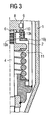
- the hermetic sealing between the fluid chamber 2 and the actuator chamber 9 is also performed by a metal bellows 10h with standard and experienced dimensions, which is rigidly and hermetically connected, e.g. by welding, at its upper collar 10i to an end stop surface of the bottom cap 8 of the piezoelectric actuator.
- the upper collar 10i might also be rigidly connected, e.g. by welding, to an end stop surface of a thermal compensator, in case such a compensator is inserted between the piezo stack 7 and the second end 6 of the valve needle 4.
- the lower collar 10j of the metal bellows 10d is rigidly and hermetically connected, e.g. by welding, to a flange or integrally formed as a flange that is rigidly and hermetically connected, e.g. by welding, to the inner cylindrical surface 11 of the valve body 1.
- the flange provides a surface oppositely arranged to the metal bellows 10d on the side of the actuator chamber 9.
- the metal bellows 10h is able to resist to the deformations due to peaks of pressure within the fluid chamber.
- an elastic element 10k might be arranged that preferably shows a cross section adapted to that of the metal bellows 10h, as shown in Fig. 3 .
- this third preferred embodiment ensures an easier manufacturing. Since also in this embodiment the helical spring 12 that provides the bias of the valve needle 4 to close the metering opening 3 is "immersed" in the fluid, the fluid chamber might be designed rather big which leads to less high peaks of pressure.
- a metering device for dosing pressurized fluids in particular an injection valve for a fuel injection system in an internal combustion engine, is disclosed in which the hermetic sealing between the fluid chamber for the pressurized fluid to be dosed and the actuator chamber is provided by an elastic element that is hermetically fastened to the valve body and to a bottom cap of the actuator assembly or a thermal compensator.
Landscapes
- Engineering & Computer Science (AREA)
- General Engineering & Computer Science (AREA)
- Mechanical Engineering (AREA)
- Chemical & Material Sciences (AREA)
- Combustion & Propulsion (AREA)
- Fuel-Injection Apparatus (AREA)
Claims (7)
- Dispositif de dosage pour doser des fluides pressurisés, en particulier une soupape d'injection pour un système d'injection de carburant dans un moteur à combustion interne, comprenant- un corps de soupape (1) ayant une chambre de fluide (2) destinée au fluide pressurisé devant être dosé, la chambre de fluide (2) se terminant par une ouverture de dosage (3),- un pointeau de soupape à déplacement axial (4) passant à travers la chambre de fluide (2), le pointeau de soupape (4) ayant une première extrémité (5) qui commande l'ouverture et la fermeture de l'ouverture de dosage (3), et une seconde extrémité (6) qui coopère avec un ensemble d'actionneur (7, 8) disposé dans une chambre d'actionneur (9), et commandant le déplacement axial du pointeau de soupape (4), et- un élément formant joint (10a - 10c ; 10d - 10g ; 10h - 10j ; 101 - 10n) isolant au plan hydraulique la chambre d'actionneur (9) et la chambre de fluide (2), l'élément formant joint (10a - 10c ; 10d - 10g ; 10h - 10j) étant constitué d'un élément élastique qui est hermétiquement fixé au corps de soupape (1) et à un culot inférieur (8) de l'ensemble d'actionneur (7, 8) ou à un compensateur thermique, lequel culot inférieur (8) est en contact avec la seconde extrémité (6) du pointeau de soupape (4), et comprenant une rondelle métallique (10a, 10b) qui est hermétiquement reliée, au niveau de son diamètre intérieur, au culot inférieur (8) de l'ensemble d'actionneur (7, 8) et, au niveau de son diamètre extérieur, à une surface cylindrique intérieure (11) du corps de soupape (1),caractérisé en ce que
l'élément formant joint comprend un anneau en caoutchouc (10c) conçu pour s'ajuster entre le culot inférieur (8) de l'ensemble d'actionneur (7, 8) ou un compensateur thermique, et la surface intérieure (11), de préférence un siège de joint (15), du corps de soupape (1), et disposé de façon à être en contact avec la rondelle métallique (10a, 10b) du côté de la chambre d'actionneur (9). - Dispositif de dosage selon la revendication 1, caractérisé en ce que
une partie conique (10a) de la rondelle métallique (10a, 10b) est conçue pour résister à une déformation due à des pics de pression générés dans la chambre de fluide (2) suite à l'impact de forces provenant du culot inférieur (8) de l'ensemble d'actionneur (7, 8) sur la seconde extrémité (6) du pointeau de soupape (4). - Dispositif de dosage pour doser des fluides pressurisés, en particulier une soupape d'injection pour un système d'injection de carburant dans un moteur à combustion interne, comprenant- un corps de soupape (1) ayant une chambre de fluide (2) destinée au fluide pressurisé devant être dosé, la chambre de fluide (2) se terminant par une ouverture de dosage (3),- un pointeau de soupape à déplacement axial (4) passant à travers la chambre de fluide (2), le pointeau de soupape (4) ayant une première extrémité (5) qui commande l'ouverture et la fermeture de l'ouverture de dosage (3), et une seconde extrémité (6) qui coopère avec un ensemble d'actionneur (7, 8) disposé dans une chambre d'actionneur (9) et commandant le déplacement axial du pointeau de soupape (4), et- un élément formant joint (10a - 10c ; 10d - 10g ; 10h - 10j ; 101 - 10n) isolant au plan hydraulique la chambre d'actionneur (9) et la chambre de fluide (2), l'élément formant joint (10a - 10c ; 10d - 10g ; 10h - 10j) étant constitué d'un élément élastique qui est hermétiquement fixé au corps de soupape (1) et à un culot inférieur (8) de l'ensemble d'actionneur (7, 8) ou à un compensateur thermique, lequel culot inférieur (8) est en contact avec la seconde extrémité (6) du pointeau de soupape (4),caractérisé en ce que
l'élément formant joint comprend un soufflet métallique (10d) qui est hermétiquement relié, au niveau de son bourrelet supérieur (10e), au culot inférieur (8) de l'ensemble d'actionneur (7, 8) ou à un compensateur thermique et, au niveau de son bourrelet inférieur (10f), à une surface cylindrique intérieure (11) du corps de soupape (1), ainsi qu'un élément en caoutchouc (10g) conçu pour s'ajuster entre le soufflet métallique (10d) et la surface intérieure (11), de préférence un siège de joint (15), du corps de soupape (1), et disposé de façon à être en contact avec le soufflet métallique (10d) du côté de la chambre d'actionneur (9). - Dispositif de dosage selon la revendication 3,
caractérisé en ce que
le soufflet métallique (10d) est conçu pour résister à une déformation due à des pics de pression générés dans la chambre de fluide (2) suite à l'impact de forces provenant du culot inférieur (8) de l'ensemble d'actionneur (7, 8) sur la seconde extrémité (6) du pointeau de soupape (4). - Dispositif de dosage pour doser des fluides pressurisés, en particulier une soupape d'injection pour un système d'injection de carburant dans un moteur à combustion interne, comprenant- un corps de soupape (1) ayant une chambre de fluide (2) destinée au fluide pressurisé devant être dosé, la chambre de fluide (2) se terminant par une ouverture de dosage (3),- un pointeau de soupape à déplacement axial (4) passant à travers la chambre de fluide (2), le pointeau de soupape (4) ayant une première extrémité (5) qui commande l'ouverture et la fermeture de l'ouverture de dosage (3), et une seconde extrémité (6) qui coopère avec un ensemble d'actionneur (7, 8) disposé dans une chambre d'actionneur (9) et commandant le déplacement axial du pointeau de soupape (4), et- un élément formant joint (10a - 10c ; 10d - 10g ; 10h - 10j ; 101 - 10n) isolant au plan hydraulique la chambre d'actionneur (9) et la chambre de fluide (2), l'élément formant joint (10a - 10c ; 10d - 10g ; 10h - 10j) étant constitué d'un élément élastique qui est hermétiquement fixé au corps de soupape (1) et à un culot inférieur (8) de l'ensemble d'actionneur (7, 8) ou à un compensateur thermique, lequel culot inférieur (8) est en contact avec la seconde extrémité (6) du pointeau de soupape (4),caractérisé en ce que
l'élément formant joint comprend- un soufflet métallique (10h) qui est hermétiquement relié, au niveau de son bourrelet supérieur (10i), au culot inférieur (8) de l'ensemble d'actionneur (7, 8) ou à un compensateur thermique,- une bride (10j) qui est hermétiquement reliée ou combinée d'un seul tenant à un bourrelet inférieur du soufflet métallique (10h) et hermétiquement soudée à une surface cylindrique intérieure (11) du corps de soupape (1), et- un élément en caoutchouc (10k) conçu pour s'ajuster entre le soufflet métallique (10h) et la bride (10j). - Dispositif de dosage selon la revendication 5,
caractérisé en ce que
le soufflet métallique (10h) est conçu pour résister à une déformation due à des pics de pression générés dans la chambre de fluide (2) suite à l'impact de forces provenant du culot inférieur (8) de l'ensemble d'actionneur (7, 8) sur la seconde extrémité (6) du pointeau de soupape (4). - Dispositif de dosage selon l'une quelconque des revendications 1 à 6,
caractérisé en ce que
la liaison hermétique entre deux éléments comprend le soudage de ces éléments.
Priority Applications (2)
| Application Number | Priority Date | Filing Date | Title |
|---|---|---|---|
| DE2003620212 DE60320212T2 (de) | 2003-02-04 | 2003-02-04 | Dosiervorrichtung mit dynamischer Dichtung |
| EP20030002399 EP1445472B1 (fr) | 2003-02-04 | 2003-02-04 | Dispositif de dosage avec joint dynamique |
Applications Claiming Priority (1)
| Application Number | Priority Date | Filing Date | Title |
|---|---|---|---|
| EP20030002399 EP1445472B1 (fr) | 2003-02-04 | 2003-02-04 | Dispositif de dosage avec joint dynamique |
Publications (2)
| Publication Number | Publication Date |
|---|---|
| EP1445472A1 EP1445472A1 (fr) | 2004-08-11 |
| EP1445472B1 true EP1445472B1 (fr) | 2008-04-09 |
Family
ID=32605312
Family Applications (1)
| Application Number | Title | Priority Date | Filing Date |
|---|---|---|---|
| EP20030002399 Expired - Fee Related EP1445472B1 (fr) | 2003-02-04 | 2003-02-04 | Dispositif de dosage avec joint dynamique |
Country Status (2)
| Country | Link |
|---|---|
| EP (1) | EP1445472B1 (fr) |
| DE (1) | DE60320212T2 (fr) |
Family Cites Families (7)
| Publication number | Priority date | Publication date | Assignee | Title |
|---|---|---|---|---|
| DE59706514D1 (de) * | 1996-09-30 | 2002-04-04 | Siemens Ag | Steller mit einem aktor mit steuerbarer länge und vorrichtung zur übertragung der auslenkung eines aktors |
| EP1046809B1 (fr) | 1999-04-20 | 2005-08-10 | Siemens Aktiengesellschaft | Dispositif de dosage d'un fluide |
| DE19946830A1 (de) * | 1999-09-30 | 2001-05-03 | Bosch Gmbh Robert | Ventil zum Steuern von Flüssigkeiten |
| DE19958704C2 (de) * | 1999-12-06 | 2002-10-02 | Siemens Ag | Vorrichtung zum Übertragen einer Aktorbewegung und Fluiddosierer mit einer solchen Vorrichtung |
| DE19962177A1 (de) * | 1999-12-22 | 2001-07-12 | Siemens Ag | Hydraulische Vorrichtung zum Übertragen einer Aktorbewegung |
| DE10016247B4 (de) * | 2000-03-31 | 2009-10-22 | Continental Automotive Gmbh | Einspritzventil mit einer Dichtmembran |
| DE10035168A1 (de) * | 2000-07-19 | 2002-02-07 | Siemens Ag | Stellantrieb, Ventil sowie Verfahren zum Herstellen eines Stellantriebs |
-
2003
- 2003-02-04 DE DE2003620212 patent/DE60320212T2/de not_active Expired - Lifetime
- 2003-02-04 EP EP20030002399 patent/EP1445472B1/fr not_active Expired - Fee Related
Also Published As
| Publication number | Publication date |
|---|---|
| DE60320212D1 (de) | 2008-05-21 |
| EP1445472A1 (fr) | 2004-08-11 |
| DE60320212T2 (de) | 2009-07-09 |
Similar Documents
| Publication | Publication Date | Title |
|---|---|---|
| US7044407B2 (en) | Fluid dosing device with a throttle point | |
| JP2005528548A (ja) | 流体のための調量装置、特に自動車用噴射弁 | |
| JP2003534512A (ja) | 圧電式アクチエータ | |
| US6948667B2 (en) | Fuel injector | |
| KR20050021538A (ko) | 압전식 액추에이터 모듈 및 그 조립 방법 | |
| EP0978650B1 (fr) | Joint d'étanchéité | |
| EP1445473B1 (fr) | Dispositif de dosage avec joint dynamique | |
| EP1445472B1 (fr) | Dispositif de dosage avec joint dynamique | |
| US6425376B1 (en) | Fuel injector | |
| JP4163962B2 (ja) | 圧電式のアクチュエータモジュール | |
| US20090102320A1 (en) | Piezoactuator | |
| US6899284B1 (en) | Fuel-injection valve | |
| EP1445480B1 (fr) | Dispositif de dosage avec joint d'étanchéité dynamique | |
| EP1391609B1 (fr) | Appareil de dosage avec une bague hydraulique | |
| US20060043213A1 (en) | Fuel injection valve | |
| EP1445478B1 (fr) | Elément d'étanchéité et aiguille de soupape pour un dispositif de dosage | |
| US20090260598A1 (en) | Arrangement with a piezoelectric actuator around which fluid media flow | |
| EP1813805A1 (fr) | Ensemble de compensation pour un injecteur | |
| EP1862668B1 (fr) | Dispositif de couplage et assemblage de liaison | |
| US20040046060A1 (en) | Fuel injection valve | |
| EP1391608B1 (fr) | Doseur avec unité de compensation thermique | |
| KR20040091753A (ko) | 연료 분사 밸브 | |
| EP3816431B1 (fr) | Injecteur de fluide pour moteur à combustion interne comprenant un élément compensateur de pression | |
| EP2067981B1 (fr) | Ensemble de vanne pour soupape d'injection, et soupape d'injection | |
| EP2476896A1 (fr) | Agencement d'actionneur à utiliser dans un injecteur de carburant |
Legal Events
| Date | Code | Title | Description |
|---|---|---|---|
| PUAI | Public reference made under article 153(3) epc to a published international application that has entered the european phase |
Free format text: ORIGINAL CODE: 0009012 |
|
| AK | Designated contracting states |
Kind code of ref document: A1 Designated state(s): AT BE BG CH CY CZ DE DK EE ES FI FR GB GR HU IE IT LI LU MC NL PT SE SI SK TR |
|
| AX | Request for extension of the european patent |
Extension state: AL LT LV MK RO |
|
| 17P | Request for examination filed |
Effective date: 20050207 |
|
| AKX | Designation fees paid |
Designated state(s): DE FR GB IT |
|
| GRAP | Despatch of communication of intention to grant a patent |
Free format text: ORIGINAL CODE: EPIDOSNIGR1 |
|
| GRAS | Grant fee paid |
Free format text: ORIGINAL CODE: EPIDOSNIGR3 |
|
| GRAA | (expected) grant |
Free format text: ORIGINAL CODE: 0009210 |
|
| AK | Designated contracting states |
Kind code of ref document: B1 Designated state(s): DE FR GB IT |
|
| REG | Reference to a national code |
Ref country code: GB Ref legal event code: FG4D |
|
| REF | Corresponds to: |
Ref document number: 60320212 Country of ref document: DE Date of ref document: 20080521 Kind code of ref document: P |
|
| ET | Fr: translation filed | ||
| PLBE | No opposition filed within time limit |
Free format text: ORIGINAL CODE: 0009261 |
|
| STAA | Information on the status of an ep patent application or granted ep patent |
Free format text: STATUS: NO OPPOSITION FILED WITHIN TIME LIMIT |
|
| 26N | No opposition filed |
Effective date: 20090112 |
|
| REG | Reference to a national code |
Ref country code: FR Ref legal event code: CD |
|
| REG | Reference to a national code |
Ref country code: FR Ref legal event code: PLFP Year of fee payment: 14 |
|
| REG | Reference to a national code |
Ref country code: FR Ref legal event code: PLFP Year of fee payment: 15 |
|
| REG | Reference to a national code |
Ref country code: FR Ref legal event code: PLFP Year of fee payment: 16 |
|
| PGFP | Annual fee paid to national office [announced via postgrant information from national office to epo] |
Ref country code: GB Payment date: 20180216 Year of fee payment: 16 |
|
| PGFP | Annual fee paid to national office [announced via postgrant information from national office to epo] |
Ref country code: FR Payment date: 20180223 Year of fee payment: 16 |
|
| GBPC | Gb: european patent ceased through non-payment of renewal fee |
Effective date: 20190204 |
|
| PG25 | Lapsed in a contracting state [announced via postgrant information from national office to epo] |
Ref country code: GB Free format text: LAPSE BECAUSE OF NON-PAYMENT OF DUE FEES Effective date: 20190204 |
|
| PG25 | Lapsed in a contracting state [announced via postgrant information from national office to epo] |
Ref country code: FR Free format text: LAPSE BECAUSE OF NON-PAYMENT OF DUE FEES Effective date: 20190228 |
|
| PGFP | Annual fee paid to national office [announced via postgrant information from national office to epo] |
Ref country code: IT Payment date: 20200225 Year of fee payment: 18 Ref country code: DE Payment date: 20200229 Year of fee payment: 18 |
|
| REG | Reference to a national code |
Ref country code: DE Ref legal event code: R084 Ref document number: 60320212 Country of ref document: DE |
|
| REG | Reference to a national code |
Ref country code: DE Ref legal event code: R119 Ref document number: 60320212 Country of ref document: DE |
|
| PG25 | Lapsed in a contracting state [announced via postgrant information from national office to epo] |
Ref country code: DE Free format text: LAPSE BECAUSE OF NON-PAYMENT OF DUE FEES Effective date: 20210901 |
|
| PG25 | Lapsed in a contracting state [announced via postgrant information from national office to epo] |
Ref country code: IT Free format text: LAPSE BECAUSE OF NON-PAYMENT OF DUE FEES Effective date: 20210204 |