EP1445471A1 - Terminal adapter and metering device comprising same - Google Patents
Terminal adapter and metering device comprising same Download PDFInfo
- Publication number
- EP1445471A1 EP1445471A1 EP03001635A EP03001635A EP1445471A1 EP 1445471 A1 EP1445471 A1 EP 1445471A1 EP 03001635 A EP03001635 A EP 03001635A EP 03001635 A EP03001635 A EP 03001635A EP 1445471 A1 EP1445471 A1 EP 1445471A1
- Authority
- EP
- European Patent Office
- Prior art keywords
- piezoelectric actuator
- adapter
- pins
- terminal adapter
- end pieces
- Prior art date
- Legal status (The legal status is an assumption and is not a legal conclusion. Google has not performed a legal analysis and makes no representation as to the accuracy of the status listed.)
- Granted
Links
- 238000005452 bending Methods 0.000 claims abstract description 15
- 239000000446 fuel Substances 0.000 claims abstract description 7
- 238000002347 injection Methods 0.000 claims description 11
- 239000007924 injection Substances 0.000 claims description 11
- 239000012530 fluid Substances 0.000 claims description 4
- 238000002485 combustion reaction Methods 0.000 claims description 2
- 230000005284 excitation Effects 0.000 description 3
- 238000009429 electrical wiring Methods 0.000 description 2
- 238000004519 manufacturing process Methods 0.000 description 2
- 238000010276 construction Methods 0.000 description 1
- 230000008602 contraction Effects 0.000 description 1
- 230000007423 decrease Effects 0.000 description 1
- 230000001419 dependent effect Effects 0.000 description 1
- 239000000463 material Substances 0.000 description 1
- 238000000034 method Methods 0.000 description 1
- 239000002991 molded plastic Substances 0.000 description 1
- 230000010355 oscillation Effects 0.000 description 1
- 230000037361 pathway Effects 0.000 description 1
- 239000000243 solution Substances 0.000 description 1
- 230000001131 transforming effect Effects 0.000 description 1
- 230000032258 transport Effects 0.000 description 1
- XLYOFNOQVPJJNP-UHFFFAOYSA-N water Substances O XLYOFNOQVPJJNP-UHFFFAOYSA-N 0.000 description 1
Images

Classifications
-
- F—MECHANICAL ENGINEERING; LIGHTING; HEATING; WEAPONS; BLASTING
- F02—COMBUSTION ENGINES; HOT-GAS OR COMBUSTION-PRODUCT ENGINE PLANTS
- F02M—SUPPLYING COMBUSTION ENGINES IN GENERAL WITH COMBUSTIBLE MIXTURES OR CONSTITUENTS THEREOF
- F02M61/00—Fuel-injectors not provided for in groups F02M39/00 - F02M57/00 or F02M67/00
- F02M61/16—Details not provided for in, or of interest apart from, the apparatus of groups F02M61/02 - F02M61/14
- F02M61/167—Means for compensating clearance or thermal expansion
-
- F—MECHANICAL ENGINEERING; LIGHTING; HEATING; WEAPONS; BLASTING
- F02—COMBUSTION ENGINES; HOT-GAS OR COMBUSTION-PRODUCT ENGINE PLANTS
- F02M—SUPPLYING COMBUSTION ENGINES IN GENERAL WITH COMBUSTIBLE MIXTURES OR CONSTITUENTS THEREOF
- F02M51/00—Fuel-injection apparatus characterised by being operated electrically
- F02M51/005—Arrangement of electrical wires and connections, e.g. wire harness, sockets, plugs; Arrangement of electronic control circuits in or on fuel injection apparatus
-
- F—MECHANICAL ENGINEERING; LIGHTING; HEATING; WEAPONS; BLASTING
- F02—COMBUSTION ENGINES; HOT-GAS OR COMBUSTION-PRODUCT ENGINE PLANTS
- F02M—SUPPLYING COMBUSTION ENGINES IN GENERAL WITH COMBUSTIBLE MIXTURES OR CONSTITUENTS THEREOF
- F02M51/00—Fuel-injection apparatus characterised by being operated electrically
- F02M51/06—Injectors peculiar thereto with means directly operating the valve needle
- F02M51/0603—Injectors peculiar thereto with means directly operating the valve needle using piezoelectric or magnetostrictive operating means
-
- F—MECHANICAL ENGINEERING; LIGHTING; HEATING; WEAPONS; BLASTING
- F02—COMBUSTION ENGINES; HOT-GAS OR COMBUSTION-PRODUCT ENGINE PLANTS
- F02M—SUPPLYING COMBUSTION ENGINES IN GENERAL WITH COMBUSTIBLE MIXTURES OR CONSTITUENTS THEREOF
- F02M61/00—Fuel-injectors not provided for in groups F02M39/00 - F02M57/00 or F02M67/00
- F02M61/04—Fuel-injectors not provided for in groups F02M39/00 - F02M57/00 or F02M67/00 having valves, e.g. having a plurality of valves in series
- F02M61/08—Fuel-injectors not provided for in groups F02M39/00 - F02M57/00 or F02M67/00 having valves, e.g. having a plurality of valves in series the valves opening in direction of fuel flow
-
- H—ELECTRICITY
- H01—ELECTRIC ELEMENTS
- H01R—ELECTRICALLY-CONDUCTIVE CONNECTIONS; STRUCTURAL ASSOCIATIONS OF A PLURALITY OF MUTUALLY-INSULATED ELECTRICAL CONNECTING ELEMENTS; COUPLING DEVICES; CURRENT COLLECTORS
- H01R13/00—Details of coupling devices of the kinds covered by groups H01R12/70 or H01R24/00 - H01R33/00
- H01R13/02—Contact members
- H01R13/04—Pins or blades for co-operation with sockets
- H01R13/05—Resilient pins or blades
-
- H—ELECTRICITY
- H01—ELECTRIC ELEMENTS
- H01R—ELECTRICALLY-CONDUCTIVE CONNECTIONS; STRUCTURAL ASSOCIATIONS OF A PLURALITY OF MUTUALLY-INSULATED ELECTRICAL CONNECTING ELEMENTS; COUPLING DEVICES; CURRENT COLLECTORS
- H01R31/00—Coupling parts supported only by co-operation with counterpart
- H01R31/06—Intermediate parts for linking two coupling parts, e.g. adapter
Definitions
- the present invention relates to a terminal adapter for an electrical connector supplying electrical power to a piezoelectric actuator in a high pressure fuel injector, in which the axially extendable piezoelectric actuator controls the axial movement of a valve needle to open and close a metering opening of the injector.
- the invention further relates to a metering device for dosing pressurized fluids comprising such a terminal adapter.
- EP 1 046 809 A2 discloses an injection valve of the above mentioned type.
- the housing and the piezoelectric actuator are generally fabricated from different materials and have different thermal coefficients of expansion, further measures must be taken to ensure that an injector valve of this type meets the requirements on the fuel flow rate and the geometry of the jet. Particularly important is the influence of the temperature on the principal functional parameters of the injector.
- the injector valves are typically equipped with a hydraulic thermal compensation unit. As the operation temperature increases, the thermal compensation unit recovers the clearance that would otherwise be created between the valve needle and the piezoelectric actuator.
- the electrical wiring connecting the upper side of the piezoelectric actuator with the outer side of the injector body must likewise permit the axial movements, i.e. the extensions and the contractions of the thermal compensator subgroup with high frequency. At the same time a reliable electrical contact to the piezoelectric actuator must be maintained.
- a bipolar and flexible wire coming out of the injector body provides the electrical connection to the piezoelectric actuator. Such a solution, however, can only be employed for test specimens and is not feasible for the standard mass production of injectors.
- a terminal adapter for an electrical connector with the features of appended claim 1.
- the invention also contains a metering device for dosing pressurized fluids comprising such a terminal adapter according to independent claim 5.
- Advantageous embodiments of the invention are disclosed in the dependent claims.
- the terminal adapter of the type mentioned above comprises a set of adapter pins, each of which has a first end piece and a second end piece, wherein the first end pieces provide electrical contact to the piezoelectric actuator and the second end pieces are adapted to be connected to an external power supply, and wherein the second end pieces have a flexible bending area allowing axial extensions of the adapter pins.
- the flexible bending area of the adapter pins is formed in an "L” shape. According to another preferred embodiment, the flexible bending area of the adapter pins may be formed in an "S" shape.
- the flexible bending area of the adapter pins is advantageously formed in a shape permitting an axial extension of the adapter pins of about 100 ⁇ m.
- pin shapes are intended to confer an increased compliance to the stiff electrical adapter pins by transforming the tensile stress on the pins arising from the axial oscillations of the thermal compensator in a reduced bending stress on the pins.
- a metering device for dosing pressurized fluids particularly an injection valve for a fuel injection system in an internal combustion engine, comprises a housing having a metering opening, whose opening and closing is controlled by the movement of an axially moveable valve needle. It further comprises an axially extendable piezoelectric actuator cooperating with the valve needle to control its axial movement, a thermal compensator unit cooperating with the piezoelectric actuator and the housing to compensate for different thermal expansion of the housing and the piezoelectric actuator to ensure elastic contact between an end stop of the housing, the piezoelectric actuator and the valve needle, and an electrical connector for supplying electrical power to the piezoelectric actuator.
- the electric connector comprises a terminal adapter of the type described above.
- the electrical connector contains a set of connector pins rigidly mounted in the body of the electrical connector and adapted to be connected with an external power supply.
- the connector pins are electrically connected to the second end pieces of the adapter pins, which are then connected to the external power supply via the connector pins.
- the second end pieces of the adapter pins are advantageously welded or braised to the connector pins.
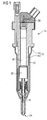
- FIG. 1 shows an injection valve for direct-injection gasoline engines, generally designated by 10.
- the injection valve has a housing 12, which comprises an outer tubular member 14 and an inner tubular member 16.
- the outer tubular member 14 forms the outer jacket of the injection valve 10
- the inner tubular member 16 contains the piezoelectric actuator 18 and the thermal compensator subgroup 20.
- the passage 22 formed between the outer tubular member 14 and the inner tubular member 16 provides a large annular pathway which transports the gasoline supplied by an entry duct to gasoline admission holes and into the outlet passage 24 of the injector valve 10.
- an excitation voltage is applied to the piezoelectric actuator 18 by an electrical connector 30, which is described in detail below.
- the piezoelectric actuator 18 increases in length in axial direction by a predetermined amount, typically about ten or several tens of micrometers. This extension in length is transmitted to a valve needle 26 disposed in the outlet passage 24, which depresses a biasing spring and lifts from its seat. In this position, the injection of pressurized gasoline in the cylinder starts.
- a thermal compensator 20 is provided to fix the position of the piezoelectric actuator 18 during fast changes of its length, but compensates for slow changes in the position of the piezoelectric actuator 18 due to, for example, thermal changes.
- FIG. 2 shows a perspective view of a partly assembled electrical connector 30 according to an embodiment of the invention.
- the electrical connector 30 has a moulded plastic connector body 32 with a terminal adapter 34 comprising a set of adapter pins 36.
- Each adapter pin 36 has a first end piece (not shown) for providing electrical contact to the piezoelectric actuator 18.
- Each adapter pin 36 further has a second end piece projecting form the terminal adapter 34 and having an "L"-shape flexible bending area allowing axial extensions of the adapter pins of about 100 ⁇ m.
- the second end pieces of the adapter pins 36 are welded or braised to connector pins projecting from the body 32 of the electrical connector 30.
- the connector pins are connected to an external power supply, whereby electrical power is supplied to the piezoelectric actuator 18 via the connector pins and the adapter pins 36.
- the shape of the flexible bending area transforms the tensile stress exerted on the adapter pins by the axial movements of the thermal compensator in a reduced bending stress.
- FIG. 3 shows a terminal adapter 34 with adapter pins 36 having an "L"-shaped flexible bending area.
- Figure 3(b) shows a terminal adapter 34 whose adapter pins 36 have flexible bending area shaped in the form of the letter "S".
Abstract
Description
- an easy assembly of the terminal adapter on the electrical connector and on the injector, avoiding any possible undesired movement of the electrical wiring;
- the possibility of using the component easily in high series production; and
- no water, gasoline or vapor intrusions are possible.
- Figure 1
- is a schematic axial cross section of an injector valve with an electrical connector according to an embodiment of the invention;
- Figure 2
- is a perspective view of a partly assembled electrical connector according to the invention; and
- Figure 3
- shows in (a) and (b) two preferred embodiments of a terminal adapter according to the invention.
Claims (7)
- A terminal adapter (34) for an electrical connector (30) supplying electrical power to a piezoelectric actuator (18) in a high pressure fuel injector (10), in which the axially extendable piezoelectric actuator (18) controls the axial movement of a valve needle (26) to open and close a metering opening of the injector (10),
characterized in that
the terminal adapter (34) comprises a set of adapter pins (36) each of which has a first end piece and a second end piece, whereinthe first end pieces provide electrical contact to the piezoelectric actuator (18) andthe second end pieces are adapted to be connected to an external power supply, and whereinthe second end pieces have a flexible bending area allowing axial extensions of the adapter pins. - A terminal adapter according to claim 1,
characterized in that
the flexible bending area of the adapter pins (36) is formed in an "L" shape. - A terminal adapter according to claim 1,
characterized in that
the flexible bending area of the adapter pins (36) is formed in an "S" shape. - A terminal adapter according any of the preceding claims,
characterized in that
the flexible bending area of the adapter pins (36) is formed in a shape permitting an axial extension of the adapter pins (36) of about 100 µm. - A metering device for dosing pressurized fluids, particularly an injection valve for a fuel injection system in an internal combustion engine, comprisingcharacterized in thata housing (12) having a metering opening, whose opening and closing is controlled by the movement of an axially moveable valve needle (26),an axially extendable piezoelectric actuator (18) cooperating with the valve needle (26) to control its axial movement,a thermal compensator unit (20) cooperating with the piezoelectric actuator (18) and the housing (12) to compensate for different thermal expansion of the housing (12) and the piezoelectric actuator (18) to ensure elastic contact between an end stop of the housing (12), the piezoelectric actuator (18) and the valve needle (26), andan electrical connector (30) for supplying electrical power to the piezoelectric actuator (18)
the electrical connector (30) comprises a terminal adapter (34) according to any one of claims 1 to 4. - The metering device according to claim 5,
characterized in that
the electrical connector (30) contains a set of connector pins rigidly mounted in the body (32) of the electrical connector (30) and adapted to be connected with an external power supply, the connector pins being electrically connected to the second end pieces of the adapter pins (36). - The metering device according to claim 5 or 6,
characterized in that
the second end pieces of the adapter pins (36) are welded or braised to the connector pins.
Priority Applications (7)
| Application Number | Priority Date | Filing Date | Title |
|---|---|---|---|
| EP03001635A EP1445471B1 (en) | 2003-01-24 | 2003-01-24 | Terminal adapter and metering device comprising same |
| DE60305289T DE60305289T2 (en) | 2003-01-24 | 2003-01-24 | Electrical connection adapter and dosing device with such a connection |
| AU2003258673A AU2003258673A1 (en) | 2003-01-24 | 2003-08-27 | Terminal adapter and metering device comprising same |
| CNB038258447A CN100376784C (en) | 2003-01-24 | 2003-08-27 | Terminal adapter and metering device comprising same |
| JP2004566747A JP2006513352A (en) | 2003-01-24 | 2003-08-27 | Terminal adapter and metering device having terminal adapter |
| PCT/EP2003/009487 WO2004065781A1 (en) | 2003-01-24 | 2003-08-27 | Terminal adapter and metering device comprising same |
| US11/188,083 US20050255731A1 (en) | 2003-01-24 | 2005-07-22 | Terminal adapter and metering device comprising same |
Applications Claiming Priority (1)
| Application Number | Priority Date | Filing Date | Title |
|---|---|---|---|
| EP03001635A EP1445471B1 (en) | 2003-01-24 | 2003-01-24 | Terminal adapter and metering device comprising same |
Publications (2)
| Publication Number | Publication Date |
|---|---|
| EP1445471A1 true EP1445471A1 (en) | 2004-08-11 |
| EP1445471B1 EP1445471B1 (en) | 2006-05-17 |
Family
ID=32605243
Family Applications (1)
| Application Number | Title | Priority Date | Filing Date |
|---|---|---|---|
| EP03001635A Expired - Fee Related EP1445471B1 (en) | 2003-01-24 | 2003-01-24 | Terminal adapter and metering device comprising same |
Country Status (7)
| Country | Link |
|---|---|
| US (1) | US20050255731A1 (en) |
| EP (1) | EP1445471B1 (en) |
| JP (1) | JP2006513352A (en) |
| CN (1) | CN100376784C (en) |
| AU (1) | AU2003258673A1 (en) |
| DE (1) | DE60305289T2 (en) |
| WO (1) | WO2004065781A1 (en) |
Cited By (1)
| Publication number | Priority date | Publication date | Assignee | Title |
|---|---|---|---|---|
| EP1712774A3 (en) * | 2005-04-11 | 2007-05-02 | Robert Bosch Gmbh | Fuel injector |
Families Citing this family (5)
| Publication number | Priority date | Publication date | Assignee | Title |
|---|---|---|---|---|
| JP4428356B2 (en) | 2006-03-31 | 2010-03-10 | 株式会社デンソー | Injector |
| US7913784B2 (en) | 2007-03-30 | 2011-03-29 | Honda Motor Co., Ltd. | Saddle ride, fuel cell powered vehicle |
| DE102007029968A1 (en) * | 2007-06-28 | 2009-01-08 | Robert Bosch Gmbh | Electrical connector as fuel injector contact for non-shearing applications |
| CN102474033B (en) * | 2009-07-01 | 2015-06-17 | 皇家飞利浦电子股份有限公司 | Low cost-low profile lead set connector |
| EP3287632A1 (en) * | 2016-08-23 | 2018-02-28 | Continental Automotive GmbH | Valve assembly for an injection valve and injection valve |
Citations (4)
| Publication number | Priority date | Publication date | Assignee | Title |
|---|---|---|---|---|
| EP0218895A1 (en) * | 1985-09-17 | 1987-04-22 | Robert Bosch Gmbh | Measure valve for determining the quantity of fluids or gases |
| WO2001006115A1 (en) * | 1999-07-14 | 2001-01-25 | Robert Bosch Gmbh | Fuel injection valve |
| EP1079097A2 (en) * | 1999-08-20 | 2001-02-28 | Delphi Technologies, Inc. | Actuator housing |
| DE10039218A1 (en) * | 2000-08-11 | 2002-02-28 | Bosch Gmbh Robert | Piezoelectric actuator arrangement, in particular for actuating a valve in a motor vehicle |
Family Cites Families (5)
| Publication number | Priority date | Publication date | Assignee | Title |
|---|---|---|---|---|
| US4613783A (en) * | 1985-07-18 | 1986-09-23 | At&T Bell Laboratories | Electronic oscillator crystal wafer mount assembly |
| US6109543A (en) * | 1996-03-29 | 2000-08-29 | Siemens Automotive Corporation | Method of preheating fuel with an internal heater |
| DE19712591A1 (en) * | 1997-03-26 | 1998-10-01 | Bosch Gmbh Robert | Fuel injector and method for manufacturing and using a fuel injector |
| US6367719B1 (en) * | 1998-10-22 | 2002-04-09 | Siemens Automotive Corporation | Electromechanical valve driver circuit and method |
| US6875058B2 (en) * | 2002-05-31 | 2005-04-05 | Caterpillar Inc. | Electrical adapter for a fuel injector with two sets of connectors |
-
2003
- 2003-01-24 DE DE60305289T patent/DE60305289T2/en not_active Expired - Fee Related
- 2003-01-24 EP EP03001635A patent/EP1445471B1/en not_active Expired - Fee Related
- 2003-08-27 CN CNB038258447A patent/CN100376784C/en not_active Expired - Fee Related
- 2003-08-27 AU AU2003258673A patent/AU2003258673A1/en not_active Abandoned
- 2003-08-27 WO PCT/EP2003/009487 patent/WO2004065781A1/en active Application Filing
- 2003-08-27 JP JP2004566747A patent/JP2006513352A/en active Pending
-
2005
- 2005-07-22 US US11/188,083 patent/US20050255731A1/en not_active Abandoned
Patent Citations (4)
| Publication number | Priority date | Publication date | Assignee | Title |
|---|---|---|---|---|
| EP0218895A1 (en) * | 1985-09-17 | 1987-04-22 | Robert Bosch Gmbh | Measure valve for determining the quantity of fluids or gases |
| WO2001006115A1 (en) * | 1999-07-14 | 2001-01-25 | Robert Bosch Gmbh | Fuel injection valve |
| EP1079097A2 (en) * | 1999-08-20 | 2001-02-28 | Delphi Technologies, Inc. | Actuator housing |
| DE10039218A1 (en) * | 2000-08-11 | 2002-02-28 | Bosch Gmbh Robert | Piezoelectric actuator arrangement, in particular for actuating a valve in a motor vehicle |
Cited By (1)
| Publication number | Priority date | Publication date | Assignee | Title |
|---|---|---|---|---|
| EP1712774A3 (en) * | 2005-04-11 | 2007-05-02 | Robert Bosch Gmbh | Fuel injector |
Also Published As
| Publication number | Publication date |
|---|---|
| EP1445471B1 (en) | 2006-05-17 |
| DE60305289T2 (en) | 2006-09-28 |
| CN1735748A (en) | 2006-02-15 |
| US20050255731A1 (en) | 2005-11-17 |
| JP2006513352A (en) | 2006-04-20 |
| WO2004065781A1 (en) | 2004-08-05 |
| CN100376784C (en) | 2008-03-26 |
| DE60305289D1 (en) | 2006-06-22 |
| AU2003258673A1 (en) | 2004-08-13 |
Similar Documents
| Publication | Publication Date | Title |
|---|---|---|
| US7385335B2 (en) | Metering device with an electrical connector | |
| US7267111B2 (en) | Fuel injector | |
| US20050255731A1 (en) | Terminal adapter and metering device comprising same | |
| US7032833B2 (en) | Fuel injection valve | |
| CN100404846C (en) | Fuel injection valve | |
| EP2075857B1 (en) | Actuator arrangement and injection valve | |
| EP1794442B1 (en) | Fuel injector with vop loss resistant valve spring for emissions-compliant engine applications i | |
| EP2003329B1 (en) | Electrical connector for an injector, actuator unit for an injector, injector and method for coupling a first connector element to a second connector element of an electrical connector for an injector | |
| EP1391607A1 (en) | Metering device | |
| EP1918571B1 (en) | Injector for dosing fluid | |
| EP1113166B1 (en) | Fuel injector with thermally isolated seat | |
| EP2003327A1 (en) | Actuator unit for an injection valve and injection valve | |
| EP2034169B1 (en) | Electrical connector, actuator unit and injector | |
| EP2107234B1 (en) | Actuator arrangement and injection valve | |
| JP5018762B2 (en) | Injector | |
| EP2055927A1 (en) | Actuator arrangement and injection valve | |
| EP2003328B1 (en) | Electrical connector for an injector | |
| EP2078846B1 (en) | Actuator arrangement and injection valve | |
| JP3888177B2 (en) | Fuel injection valve | |
| EP1884654A1 (en) | Piezo-actuator-unit for an injector |
Legal Events
| Date | Code | Title | Description |
|---|---|---|---|
| PUAI | Public reference made under article 153(3) epc to a published international application that has entered the european phase |
Free format text: ORIGINAL CODE: 0009012 |
|
| AK | Designated contracting states |
Kind code of ref document: A1 Designated state(s): AT BE BG CH CY CZ DE DK EE ES FI FR GB GR HU IE IT LI LU MC NL PT SE SI SK TR |
|
| AX | Request for extension of the european patent |
Extension state: AL LT LV MK RO |
|
| 17P | Request for examination filed |
Effective date: 20050207 |
|
| 17Q | First examination report despatched |
Effective date: 20050309 |
|
| AKX | Designation fees paid |
Designated state(s): DE ES FR GB IT |
|
| GRAP | Despatch of communication of intention to grant a patent |
Free format text: ORIGINAL CODE: EPIDOSNIGR1 |
|
| GRAS | Grant fee paid |
Free format text: ORIGINAL CODE: EPIDOSNIGR3 |
|
| GRAA | (expected) grant |
Free format text: ORIGINAL CODE: 0009210 |
|
| AK | Designated contracting states |
Kind code of ref document: B1 Designated state(s): DE ES FR GB IT |
|
| PG25 | Lapsed in a contracting state [announced via postgrant information from national office to epo] |
Ref country code: IT Free format text: LAPSE BECAUSE OF FAILURE TO SUBMIT A TRANSLATION OF THE DESCRIPTION OR TO PAY THE FEE WITHIN THE PRESCRIBED TIME-LIMIT;WARNING: LAPSES OF ITALIAN PATENTS WITH EFFECTIVE DATE BEFORE 2007 MAY HAVE OCCURRED AT ANY TIME BEFORE 2007. THE CORRECT EFFECTIVE DATE MAY BE DIFFERENT FROM THE ONE RECORDED. Effective date: 20060517 |
|
| REG | Reference to a national code |
Ref country code: GB Ref legal event code: FG4D |
|
| REF | Corresponds to: |
Ref document number: 60305289 Country of ref document: DE Date of ref document: 20060622 Kind code of ref document: P |
|
| PG25 | Lapsed in a contracting state [announced via postgrant information from national office to epo] |
Ref country code: ES Free format text: LAPSE BECAUSE OF FAILURE TO SUBMIT A TRANSLATION OF THE DESCRIPTION OR TO PAY THE FEE WITHIN THE PRESCRIBED TIME-LIMIT Effective date: 20060828 |
|
| ET | Fr: translation filed | ||
| PLBE | No opposition filed within time limit |
Free format text: ORIGINAL CODE: 0009261 |
|
| STAA | Information on the status of an ep patent application or granted ep patent |
Free format text: STATUS: NO OPPOSITION FILED WITHIN TIME LIMIT |
|
| 26N | No opposition filed |
Effective date: 20070220 |
|
| PGFP | Annual fee paid to national office [announced via postgrant information from national office to epo] |
Ref country code: DE Payment date: 20090122 Year of fee payment: 7 |
|
| PGFP | Annual fee paid to national office [announced via postgrant information from national office to epo] |
Ref country code: GB Payment date: 20090122 Year of fee payment: 7 |
|
| PGFP | Annual fee paid to national office [announced via postgrant information from national office to epo] |
Ref country code: IT Payment date: 20090127 Year of fee payment: 7 |
|
| PGFP | Annual fee paid to national office [announced via postgrant information from national office to epo] |
Ref country code: FR Payment date: 20090115 Year of fee payment: 7 |
|
| GBPC | Gb: european patent ceased through non-payment of renewal fee |
Effective date: 20100124 |
|
| REG | Reference to a national code |
Ref country code: FR Ref legal event code: ST Effective date: 20100930 |
|
| PG25 | Lapsed in a contracting state [announced via postgrant information from national office to epo] |
Ref country code: FR Free format text: LAPSE BECAUSE OF NON-PAYMENT OF DUE FEES Effective date: 20100201 |
|
| PG25 | Lapsed in a contracting state [announced via postgrant information from national office to epo] |
Ref country code: DE Free format text: LAPSE BECAUSE OF NON-PAYMENT OF DUE FEES Effective date: 20100803 |
|
| PG25 | Lapsed in a contracting state [announced via postgrant information from national office to epo] |
Ref country code: GB Free format text: LAPSE BECAUSE OF NON-PAYMENT OF DUE FEES Effective date: 20100124 |
|
| PG25 | Lapsed in a contracting state [announced via postgrant information from national office to epo] |
Ref country code: IT Free format text: LAPSE BECAUSE OF NON-PAYMENT OF DUE FEES Effective date: 20100124 |