EP1445232A1 - Vehicle suspension system - Google Patents
Vehicle suspension system Download PDFInfo
- Publication number
- EP1445232A1 EP1445232A1 EP03250859A EP03250859A EP1445232A1 EP 1445232 A1 EP1445232 A1 EP 1445232A1 EP 03250859 A EP03250859 A EP 03250859A EP 03250859 A EP03250859 A EP 03250859A EP 1445232 A1 EP1445232 A1 EP 1445232A1
- Authority
- EP
- European Patent Office
- Prior art keywords
- axle
- articulation
- range
- frame
- suspension system
- Prior art date
- Legal status (The legal status is an assumption and is not a legal conclusion. Google has not performed a legal analysis and makes no representation as to the accuracy of the status listed.)
- Granted
Links
Images


Classifications
-
- B—PERFORMING OPERATIONS; TRANSPORTING
- B60—VEHICLES IN GENERAL
- B60G—VEHICLE SUSPENSION ARRANGEMENTS
- B60G9/00—Resilient suspensions of a rigid axle or axle housing for two or more wheels
- B60G9/02—Resilient suspensions of a rigid axle or axle housing for two or more wheels the axle or housing being pivotally mounted on the vehicle, e.g. the pivotal axis being parallel to the longitudinal axis of the vehicle
-
- B—PERFORMING OPERATIONS; TRANSPORTING
- B66—HOISTING; LIFTING; HAULING
- B66F—HOISTING, LIFTING, HAULING OR PUSHING, NOT OTHERWISE PROVIDED FOR, e.g. DEVICES WHICH APPLY A LIFTING OR PUSHING FORCE DIRECTLY TO THE SURFACE OF A LOAD
- B66F9/00—Devices for lifting or lowering bulky or heavy goods for loading or unloading purposes
- B66F9/06—Devices for lifting or lowering bulky or heavy goods for loading or unloading purposes movable, with their loads, on wheels or the like, e.g. fork-lift trucks
- B66F9/075—Constructional features or details
- B66F9/07586—Suspension or mounting of wheels on chassis
Definitions
- FIG. 2 is a top-view of the steer axle 20 used in the lift truck 10 shown in FIG. 1.
- the rear wheels 14 are attached to opposite ends of the steer axle 20.
- Stubs 20A and 20B extend from the opposite back and front ends, respectively, of the steer axle 20.
- a pair of brackets 22A and 22B are bolted to the truck frame 24 and hold the stubs 20A and 20B, respectively.
- FIG. 6 shows a rear view of the steer axle 20 while the tire for left steer wheel 14 traverses over an object 55. As the tire rolls over the object 55, the steer axle 20 pivots in a clockwise direction about the center point 25 previously shown in FIG. 5. The clockwise pivoting of the steer axle 20 moves the articulation stop 32A into contact with the frame 24.
- the left end of rigid steer axle 20 continues to move upward after articulation stop 32A contacts frame 24. This causes the stub 20A to compress bushing 50 downward.
- the steer axle 20 in this condition pivots about articulation stop 32A at location W.
- the downward movement of the stub 20A moves the bushing 50 downward partially filling in gaps 52A and 52B (FIG. 5).
- the center point of stubs 20A and 20B move vertically downward from location 25 to location 27.
- the pivot point of the steer axle 20 effectively moves laterally out from center line y to the articulation stop 32A at location W.
- the steer axle 20 may continue to articulate until a bottom end 53 and sides 57 of the rubber bushing 50 fill in a certain portion of the gaps 52A and 52B (FIG.5). In this fully compressed state, the steer axle 20 and the frame 24 move into a semi-rigid fixed relationship with each other. Any additional articulation of the steer axle 20 at this point also articulates the frame 24.
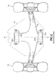
- FIG. 7 is a top view of the chassis for the lift truck 10 shown in FIG. 1 that uses the suspension system 15 previously shown in FIGS. 5 and 6.
- the drive wheels 12 are attached to the drive axle 40 and the steer wheels 14 are attached to the steer axle 20.
- the drive axle 40 is rigidly affixed to frame 24 and does not pivot independently with respect to frame 24.
- the steer axle 20 pivots about the frame centerline AB in a first articulation range prior to one of the articulation stops 32A or 32B (FIG. 5) contacting frame 24.
- the lift truck has the triangular stability profile RSV defined by the points R, S, and V.
- one of the articulation stops 32A or 32B contacts the frame 24 as previously shown in FIG. 6. This may happen, for example, when the tire for one of the steer wheels 14 travels over an object.
- the lift truck 10 transitions from the triangular stability profile RSV to a trapezoidal stability profile RSUW corresponding to locations R, S, U, and W.
- the steer axle stubs 20A and 20B can no longer move downward in bushings 50.
- the gaps 52A and 52B (FIG. 5) are substantially filled in by portions of the rubber bushing 50.
- the lift truck 10 transitions to a stability profile RSXT approaching a rectangular shape.
- the stability profile RSXT is larger than the trapezoidal stability profile RSWU and extends out to the wheels 12 and 14.
- any further lateral articulation of the steer axle 20 causes substantially the same amount of lateral articulation in frame 24.
- the steer axle 20 rotates laterally about center line 90 and the articulation stops 32A and 32B do not contact frame 24. This produces a triangular stability profile similar to triangular stability profile RSV shown in FIG. 7.
Landscapes
- Engineering & Computer Science (AREA)
- Mechanical Engineering (AREA)
- Transportation (AREA)
- Structural Engineering (AREA)
- Civil Engineering (AREA)
- Life Sciences & Earth Sciences (AREA)
- Geology (AREA)
- Vehicle Body Suspensions (AREA)
- Forklifts And Lifting Vehicles (AREA)
- Body Structure For Vehicles (AREA)
Abstract
Description
- In the accompanying drawings FIG. 1 shows a
conventional lift truck 10 whose basic function of lifting and transporting cargo is well-known.Drive wheels 12 are connected to a drive axle (not shown) andsteer wheels 14 are connected to asteer axle 20 shown in FIG. 2. The drive axle is rigidly connected to the frame oflift truck 10. Thesteer axle 20 is used for steering thetruck 10 and includes a suspension system shown in more detail in FIG. 2. - FIG. 2 is a top-view of the
steer axle 20 used in thelift truck 10 shown in FIG. 1. Therear wheels 14 are attached to opposite ends of thesteer axle 20. Stubs 20A and 20B extend from the opposite back and front ends, respectively, of thesteer axle 20. A pair of brackets 22A and 22B are bolted to thetruck frame 24 and hold the stubs 20A and 20B, respectively. - FIG. 3 is a rear sectional view of the
steer axle 20. From this view, only bracket 22A is shown. Bracket 22B is similar to bracket 22A. The stub 20A of thesteer axle 20 is centered about acenter point 21. The stub 20A is held in substantially the same relative position within the bracket 22A aboutcenter point 21 by a rubber bushing 30. Therubber bushing 30 allows thesteer axle 20 to pivot about thecenter point 21 when thesteer axle 20 articulates (laterally inclines) either clockwise or counter clockwise. - Two articulation stops 32A and 32B are located on the upper surface of the
steer axle 20. The spaces between the articulation stops 32A and 32B and thetruck frame 24 are referred to as articulation gaps 34A and 34B, respectively. When thelift truck 10 is at rest, or traveling in a straight line onlevel terrain 31, there is little articulation of thesteer axle 20 and the articulation gaps 34A and 34B remain relatively constant. - As long as the articulation stops 32A and 32B do not contact
frame 24, thesteer axle 20 is free to pivot aboutcenter point 21 independently of theframe 24. This pivoting ofsteer axle 20 allows thelift truck 10 to maneuver over uneven terrain and obstacles, or make turns, without effecting the lateral displacement of theframe 24. - The size of the articulation gaps 34A and 34B determine how far the
steer axle 20 can articulate without laterally displacing theframe 24. If thesteer axle 20 articulates far enough on one side, one of the articulation stops 32A or32B contacts frame 24. In this articulation stop contact position, any further lateral articulation of thesteer axle 20 equally articulates theframe 24. - Larger articulation gaps 34A and 34B can increase how much the
steer axle 20 can articulate before one of the articulation stops 32A and32B contacts frame 24. Larger articulation gaps 34A and 34B allow more articulation of thesteer axle 20 without laterally displacing theframe 24. - FIG. 4 shows stability profiles for the suspension system shown in FIGS. 2 and 3. The
lift truck 10 has a triangular stability profile RSU when the articulation stops 32A and 32B (FIG. 3) are not contacting thetruck frame 24. With the triangular stability profile RSU, thelift truck frame 24 is supported at the R and S locations ofdrive tires 12 and at a U location along the centerline of thesteer axle 20. - The
lift truck 10 changes to more of a rectangular shaped stability profile RSTV when either of the articulation stops 32A or 32B come in contact with theframe 24. When thesteer axle 20 pivots sufficiently to contact either one of the articulation stops 32A or 32B (FIG. 3), thesteer axle 20 moves into a rigid non-pivoting relationship with theframe 24. This moves the lateral support locations for the rear end offrame 24 from centerline location U out to the T and V locations at therear wheels 14. - According to the present invention a vehicle suspension system couples an axle to a vehicle frame so that the axle pivots about a first location with respect to the frame when the axle has a first range of articulation. The axle pivots about a second location with respect to the frame extending laterally out from the first location when the axle has a second range of articulation greater than the first range of articulation. When the axle exceeds the second range of articulation, the suspension system retains the axle in a substantially rigid contact with the vehicle frame.
- The invention will be further described by way of example with reference to the accompanying drawings, in which:-
- FIG. 1 is a drawing of a lift truck.
- FIG. 2 is a top view of a steer axle used in the lift truck shown in FIG. 1.
- FIG. 3 is a rear sectional view of the steer axle shown in FIG. 2.
- FIG. 4 is a top view of the chassis for the lift truck shown in FIG. 1.
- FIG. 5 is a rear sectional view of a suspension system according to one embodiment of the invention.
- FIG. 6 is a rear view of the suspension system shown in FIG. 5 when the lift truck is traversing over uneven terrain.
- FIG. 7 is a top view of the lift truck chassis showing the stability profiles provided by the suspension system shown in FIGS. 5 and 6.
- FIGS. 8A-8B are rear-sectional views of a suspension system according to another embodiment of the invention.
-
- FIG. 5 shows a
suspension system 15 that includes a bracket 22A rigidly connected to thetruck frame 24. The bracket 22A contains arubber bushing 50 having ahole 23 that receives the steer axle stub 20A previously shown in FIG. 2. Asimilar bushing 50 is also located at the front end of thesteer axle 20 contained in the bracket 22B shown in FIG. 2. - The shape of
bushings 50 promotes vertical compression or vertical movement of thebushing 50 when sufficient downward force is applied by the stub 20A. In one embodiment, the shape of bushing 50forms cavities concave spacing 52A in the bottom of bracket 22A andlateral spaces 52B on the sides of bracket 22A. However, other bushing shapes can also be used that allow a vertical downward compression. Different types of elastomeric material can be used for thebushings 50. - When sufficient downward force is applied at the stubs 20A and 20B, the
cavities bushing 50 to move downward enabling thecenter point 25 of the king pins 20A and 20B to also move in a downward vertical direction. FIG. 6 shows a rear view of thesteer axle 20 while the tire forleft steer wheel 14 traverses over anobject 55. As the tire rolls over theobject 55, thesteer axle 20 pivots in a clockwise direction about thecenter point 25 previously shown in FIG. 5. The clockwise pivoting of thesteer axle 20 moves thearticulation stop 32A into contact with theframe 24. - If the articulation of
steer axle 20 is large enough, the left end ofrigid steer axle 20 continues to move upward afterarticulation stop 32A contacts frame 24. This causes the stub 20A to compress bushing 50 downward. Thesteer axle 20 in this condition pivots aboutarticulation stop 32A at location W. The downward movement of the stub 20A moves the bushing 50 downward partially filling ingaps location 25 tolocation 27. The pivot point of thesteer axle 20 effectively moves laterally out from center line y to thearticulation stop 32A at location W. - The
steer axle 20 may continue to articulate until a bottom end 53 andsides 57 of the rubber bushing 50 fill in a certain portion of thegaps steer axle 20 and theframe 24 move into a semi-rigid fixed relationship with each other. Any additional articulation of thesteer axle 20 at this point also articulates theframe 24. - In an alternative embodiment, rubber bushings, or some other type of elastomeric material, can be located on the tops of the
articulation stops frame 24. - FIG. 7 is a top view of the chassis for the
lift truck 10 shown in FIG. 1 that uses thesuspension system 15 previously shown in FIGS. 5 and 6. Thedrive wheels 12 are attached to thedrive axle 40 and thesteer wheels 14 are attached to thesteer axle 20. Thedrive axle 40 is rigidly affixed to frame 24 and does not pivot independently with respect to frame 24. - The
steer axle 20 pivots about the frame centerline AB in a first articulation range prior to one of the articulation stops 32A or 32B (FIG. 5) contactingframe 24. In this articulation stop non-contact condition, the lift truck has the triangular stability profile RSV defined by the points R, S, and V. - When the
steer axle 20 moves into a second articulation range, one of the articulation stops 32A or 32B contacts theframe 24 as previously shown in FIG. 6. This may happen, for example, when the tire for one of thesteer wheels 14 travels over an object. When one of the articulation stops contact theframe 24, thelift truck 10 transitions from the triangular stability profile RSV to a trapezoidal stability profile RSUW corresponding to locations R, S, U, and W. - The points R and S correspond to locations on the
drive wheels 12. The locations W and U correspond to the locations where the articulation stops 32A and 32B, respectively, contact theframe 24. After thearticulation stop frame 24, the steer axle stubs 20A and 20B start compressingbushing 50 in a downward direction as described above in FIG. 6. This allows the steer axle 20 (FIG. 6) to pivot about point W or point U. - The pivot point of the
steer axle 20 effectively moves from location V to location W or location U. In the second articulation range when thetruck 10 has the trapezoidal stability profile RSWU, thesteer axle 20 still articulates semi-independently from theframe 24. This trapezoidal stability profile is caused by the vertical displacement of the stubs 20A and 20B inside of bushings 50 (FIG. 6). - In a third steer axle articulation range, the steer axle stubs 20A and 20B can no longer move downward in
bushings 50. For example, when thegaps rubber bushing 50. In this fully compressed bushing state, thelift truck 10 transitions to a stability profile RSXT approaching a rectangular shape. The stability profile RSXT is larger than the trapezoidal stability profile RSWU and extends out to thewheels steer axle 20 causes substantially the same amount of lateral articulation inframe 24. - In the embodiment of the invention described in FIGS. 5-7, the shape of
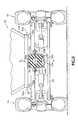
bushing 50 allows vertical displacement of the steer axle center pivot point. One of ordinary skill in the art will recognize that other bushing shapes could also be used that enable a center pivot point of an axle to move vertically up and down. - For example, FIGS. 8A and 8B show an alternative embodiment that uses compression coil springs 82, 83, 84, and 85. The upper springs 82 and 84 are somewhat larger than the
lower springs bracket weldment 80 attaches thesteer axle 20 to frame 24. A steer axle casting 88 is formed as part of thesteer axle 20 or is a separate piece rigidly welded or bolted to thesteer axle 20. - Four
bolts 87 are arranged in a square pattern and run throughopenings 86 in the mountingbracket weldment 80 attaching to theframe 24. The steer axle casting 88 includes T shaped posts 91 on opposite ends that insert inside of both theupper springs lower springs rubber bushing 89 sits between the steer axle casting 88 andweldment 80.Washers 93 retain therubber bushing 93 and protect thebushing 89 from thesprings frame 24 is supported on theupper springs - In a first articulation range, the
steer axle 20 rotates laterally aboutcenter line 90 and the articulation stops 32A and 32B do not contactframe 24. This produces a triangular stability profile similar to triangular stability profile RSV shown in FIG. 7. - If the
steer axle 20 continues to articulate either clockwise or counter clockwise, thearticulation stop 32B contacts frame 24 and combinations of thesprings weldment 80. Thesteer axle 20 is allowed to pivot about thearticulation stop frame 24 providing a trapezoidal stability profile similar to trapezoidal profile RSUW shown in FIG. 7. - In a third articulation range, the steer axle casting 88 fully compresses a combination of the
springs steer axle 20 in this condition has a substantially rigid non-pivoting contact withframe 24. The suspension system in this state exhibits a larger stability profile approaching a rectangular shape similar to the stability profile RSXT shown in FIG. 7. - Other spring designs such as Bellville springs may be used for providing the variable suspension profiles shown above. Alternatively, a single traverse set of variable leaf springs that are stiffer in the upward direction than in the downward direction can be used to bridge the front and rear mounting locations of the
steer axle 20. For example, the leaf springs can bridge the locations where brackets 22A and 22B are located in FIG. 2. Any other different combination of springs or bushings can also be used to vary the stability profiles of the lift truck as described above. - The embodiment of the invention described in FIGS. 5-7 is a passive system. That is, the
bushing 50 merely reacts to laterally applied forces. One of ordinary skill in the art will recognize that an active system may also be used to perform the same function. For example, a hydraulic system may be used to directly raise or lower the center pivot point 25 (FIG. 5) of thesteer axle 20 according to sensor inputs. Active systems could also adaptively adjust a spring constant of the movable pivot point according to the weight of the load carried by the lift truck or the degree of lateral inclination of the lift truck. - Having described and illustrated the principles of the invention in a preferred embodiment thereof, it should be apparent that the invention may be modified in arrangement and detail without departing from such principles. We claim all modifications and variation coming within the spirit and scope of the following claims.
Claims (23)
- An apparatus comprising:a coupling device coupling an axle to a vehicle frame, the coupling device providing variable suspension pivot points for the axle with respect to the frame according to a lateral inclination of the axle.
- The apparatus of claim 1 wherein the coupling device restricts lateral movement of an axle center point with respect to the frame while allowing vertical movement of the axle center point with respect to the frame.
- The apparatus according to claim 2 wherein the coupling device maintains the axle in substantially rigid non-pivoting contact with the frame after the axle exceeds a given inclination range.
- The apparatus of claim 1, 2 or 3 wherein the coupling device comprises an elastomeric bushing.
- The apparatus of claim 4 wherein the bushing includes cavities formed in a bottom end for promoting vertical compression.
- The apparatus of claim 4 or 5 wherein the bushing is formed from a unitary piece of rubber having a center hole for receiving an axle extension, the bushing allowing the extension to rotate about a center axis and also move vertically downward when a sufficient downward force is applied by the extension.
- The apparatus of claim 1, 2 or 3 wherein the coupling device comprises springs retaining a center extension of the axle.
- The apparatus of any one of the preceding claims wherein the vehicle frame produces a triangular stability profile when the axle is in a first articulation range, a trapezoidal stability profile when the axle is in a second articulation range, and a third larger stability profile approaching a rectangular shape when the axle is in a third articulation range.
- The apparatus according to any one of the preceding claims including articulation stops located on lateral ends of the axle, the coupling device allowing the axle to rotate about a center line of the axle when the articulation stops are not contacting the axle and the coupling device allowing the axle to rotate about one of the articulation stops when that articulation stop is in contact with the axle.
- A method for providing vehicle suspension, comprising:coupling an axle to a vehicle frame so that the axle pivots about a first location with respect to the frame when the axle operates within a first articulation range and the axle pivots about a second location with respect to the frame extending laterally out from the first location when the axle operates within a second articulation range greater than the first articulation range.
- The method of claim 10 including providing a first stability profile when the axle pivots about the first location, a second larger stability profile when the axle pivots about the second location and providing a third stability profile larger than the second stability profile when the axle has a third range of articulation greater than the second range of articulation.
- The method of claim 10 or 11 including pivoting the axle approximately about a centerline of the vehicle frame when the axle is operating within the first articulation range.
- The method of claim 10, 11 or 12 including pivoting the axle approximately about an articulation stop contacting the frame when the axle is operating within the second articulation range.
- The method of claim 10, 11, 12 or 13 including retaining a center location of the axle at substantially a same distance from the vehicle frame when the axle operates within the first articulation range and allowing the center location of the axle to vary or move vertically away from the vehicle frame when operating in the second articulation range.
- The method according to claim 14 including retaining the axle in a substantially rigid contact with the vehicle frame when the axle operates in a third articulation range greater than the second articulation range.
- A vehicle suspension system, comprising:a vehicle frame;an axle; andan attachment mechanism coupling the axle to the vehicle frame so that the axle pivots at different lateral positions in relationship to the frame according to an amount of lateral displacement of the axle.
- The suspension system of claim 16 wherein the axle comprises a steer axle of a truck.
- The suspension system of claim 16 or 17 including articulation stops located on opposite sides of the axle each maintaining an articulation gap with the vehicle frame when the axle operates within a first range of lateral displacement.
- The suspension system according to claim 18 wherein the axle pivots about a first central axis of the axle when the axle operates within the first range of lateral displacement and pivots about one of the articulation stops when that articulation stop contacts the vehicle frame and the axle operates within a second range of lateral displacement.
- The suspension system of claim 19 wherein the attachment mechanism prevents further pivoting of the axle about the contacting articulation stop when the axle operates within a third range of lateral displacement greater than the second range of lateral displacement.
- The suspension system of any one of claims 16 to 20 wherein the attachment mechanism retains an axle extension and allows the axle extension to move vertically up and down inside the attachment mechanism.
- The suspension system of claim 21 wherein the attachment mechanism includes a rubber bushing.
- The suspension system of claim 21 wherein the attachment mechanism includes springs.
Applications Claiming Priority (2)
| Application Number | Priority Date | Filing Date | Title |
|---|---|---|---|
| US318434 | 2002-12-13 | ||
| US10/318,434 US6959936B2 (en) | 2002-12-13 | 2002-12-13 | Vehicle suspension system |
Publications (2)
| Publication Number | Publication Date |
|---|---|
| EP1445232A1 true EP1445232A1 (en) | 2004-08-11 |
| EP1445232B1 EP1445232B1 (en) | 2009-07-22 |
Family
ID=32506337
Family Applications (1)
| Application Number | Title | Priority Date | Filing Date |
|---|---|---|---|
| EP03250859A Expired - Lifetime EP1445232B1 (en) | 2002-12-13 | 2003-02-12 | Vehicle suspension system |
Country Status (5)
| Country | Link |
|---|---|
| US (1) | US6959936B2 (en) |
| EP (1) | EP1445232B1 (en) |
| JP (1) | JP3771550B2 (en) |
| DE (1) | DE60328453D1 (en) |
| ES (1) | ES2328681T3 (en) |
Cited By (5)
| Publication number | Priority date | Publication date | Assignee | Title |
|---|---|---|---|---|
| WO2013085861A1 (en) | 2011-12-08 | 2013-06-13 | Saudi Basic Industries Corporation | Mixed oxide based catalyst for the conversion of carbon dioxide to syngas and method of preparation and use |
| WO2014003817A1 (en) | 2012-06-29 | 2014-01-03 | Saudi Basic Industries Corporation | Method of forming a syngas mixture |
| US8658554B2 (en) | 2009-11-04 | 2014-02-25 | The United States Of America, As Represented By The Secretary Of The Navy | Catalytic support for use in carbon dioxide hydrogenation reactions |
| WO2015066117A1 (en) | 2013-10-29 | 2015-05-07 | Saudi Basic Industries Corporation | Method for carbon dioxide hydrogenation of syngas and the integration of the process with syngas conversion processes |
| WO2015103592A1 (en) | 2014-01-06 | 2015-07-09 | Saudi Basic Industries Corporation | Method for carbon dioxide hydrogenation of syngas |
Families Citing this family (13)
| Publication number | Priority date | Publication date | Assignee | Title |
|---|---|---|---|---|
| US7740084B2 (en) * | 2000-05-02 | 2010-06-22 | Lyn Rosenboom | Agricultural implement frame, track assembly and cart |
| US7726749B2 (en) * | 2001-05-02 | 2010-06-01 | Lyn Rosenboom | Track assembly with bogie wheel structure |
| US7380892B2 (en) * | 2001-05-02 | 2008-06-03 | Lyn Rosenboom | Track assembly with idler wheels and cart incorporating same |
| US8967737B2 (en) | 2010-06-30 | 2015-03-03 | Camoplast Solideal Inc. | Wheel of a track assembly of a tracked vehicle |
| KR101620823B1 (en) * | 2010-08-02 | 2016-05-12 | 주식회사 두산 | Steer axle assy mounting structure for a heavy equipment |
| US9505454B1 (en) | 2011-06-13 | 2016-11-29 | Camso Inc. | Track assembly for traction of an off-road vehicle |
| US10875591B2 (en) | 2015-08-04 | 2020-12-29 | Camso Inc. | Track system for traction of an agricultural vehicle travelling on fields and roads |
| US10525783B1 (en) * | 2015-10-21 | 2020-01-07 | Rf Products, Inc. | Suspension system |
| JP6754630B2 (en) * | 2016-06-27 | 2020-09-16 | 株式会社クボタ | Axle device |
| DE102017221375A1 (en) * | 2017-11-29 | 2019-05-29 | Zf Friedrichshafen Ag | Industrial truck with a pendulum axle |
| WO2020205153A1 (en) * | 2019-04-05 | 2020-10-08 | Oshkosh Corporation | Oscillating axle for lift device |
| US11383570B2 (en) * | 2019-12-23 | 2022-07-12 | The Raymond Corporation | Systems and methods for a material handling vehicle with an articulating axle |
| US11607910B1 (en) * | 2022-03-01 | 2023-03-21 | Caterpillar Inc. | Axle oscillation stop for construction machine |
Citations (8)
| Publication number | Priority date | Publication date | Assignee | Title |
|---|---|---|---|---|
| US1120036A (en) * | 1913-01-16 | 1914-12-08 | David M Dearing | Running-gear for motor-vehicles. |
| US2835507A (en) * | 1955-06-07 | 1958-05-20 | Otis Elevator Co | Axle mounting for a vehicle |
| US3872941A (en) * | 1974-01-23 | 1975-03-25 | Caterpillar Tractor Co | Equalizer bar oscillation stop and protective guard |
| US3929346A (en) * | 1974-04-17 | 1975-12-30 | Eaton Corp | Steering axle assembly providing improved lateral stability |
| JPS60124512A (en) * | 1983-12-08 | 1985-07-03 | Toyoda Autom Loom Works Ltd | Suspension system for fork-lift truck |
| JPH03193515A (en) * | 1989-12-22 | 1991-08-23 | Toyota Autom Loom Works Ltd | Suspension device for axle beam of industrial vehicle |
| JPH06106930A (en) * | 1992-09-30 | 1994-04-19 | Nissan Motor Co Ltd | Swing control structure in rear-wheel steering vehicle |
| US6056304A (en) * | 1997-05-16 | 2000-05-02 | Clark-Hurth Components S.P.A. | Elastic suspension for industrial vehicle axles and the like |
Family Cites Families (23)
| Publication number | Priority date | Publication date | Assignee | Title |
|---|---|---|---|---|
| US1164925A (en) * | 1914-11-11 | 1915-12-21 | Clark E Clapp | Automobile attachment. |
| DE870503C (en) * | 1940-06-07 | 1953-03-16 | Daimler Benz Ag | Motor vehicle, especially with swinging half axles |
| DE872007C (en) * | 1940-06-19 | 1953-03-26 | Daimler Benz Ag | Flexible connection of an axle assembly with the frame or vehicle superstructure |
| US2978050A (en) * | 1958-10-28 | 1961-04-04 | Caterpillar Tractor Co | Front end suspension for tractors |
| US3738665A (en) * | 1972-01-03 | 1973-06-12 | Raymond Corp | Hydraulic seals |
| US3778080A (en) * | 1972-05-15 | 1973-12-11 | Raymond Corp | Lift truck load wheel arrangement |
| JPS5849432A (en) | 1981-07-21 | 1983-03-23 | フオスタ−・ホイ−ラ−・エナ−ジイ・コ−ポレイシヨン | Fluidized bed type reactor |
| JPS58218408A (en) | 1982-06-12 | 1983-12-19 | Nissan Motor Co Ltd | Rear suspension device of car |
| IT1180109B (en) * | 1984-11-05 | 1987-09-23 | Roberto Perlini | VEHICLE AXLE ANCHORING SYSTEM WITH VERTICAL STROKE SUSPENSION USING ROTARY JOINTS |
| JPS61179009A (en) | 1985-01-31 | 1986-08-11 | 日本特殊陶業株式会社 | Alumina ceramics composition |
| US4721187A (en) * | 1987-03-23 | 1988-01-26 | The Raymond Corporation | Lift truck mast structure |
| US4754837A (en) * | 1987-04-30 | 1988-07-05 | The Raymond Corporation | Lift truck steering apparatus |
| US4813512A (en) * | 1987-06-15 | 1989-03-21 | The Raymond Corporation | Idler wheel assemblies |
| SU1530519A2 (en) * | 1988-03-09 | 1989-12-23 | Всесоюзный Научно-Исследовательский Институт Коневодства | Single-horse drawn vehicle |
| JPH0373597A (en) | 1989-08-15 | 1991-03-28 | Nippon Telegr & Teleph Corp <Ntt> | Device for making temperature of electronic apparatus uniform |
| US5039924A (en) * | 1990-05-07 | 1991-08-13 | Raymond Corporation | Traction motor optimizing system for forklift vehicles |
| US5070283A (en) * | 1990-05-07 | 1991-12-03 | Raymond | Traction motor controller for forklift vehicles |
| US5123081A (en) * | 1990-07-27 | 1992-06-16 | Raymond Corporation | Temperature control system for motors and power components of a material handling vehicle |
| US5113344A (en) * | 1990-07-27 | 1992-05-12 | Raymond Corporation | Material handling vehicle identification tag |
| JPH04339005A (en) | 1991-05-14 | 1992-11-26 | Toyota Autom Loom Works Ltd | Fitting device for rear axle beam |
| USD335741S (en) * | 1991-09-09 | 1993-05-18 | Raymond Corporation | Control handle for a material handling vehicle |
| KR0166131B1 (en) * | 1994-12-30 | 1998-12-01 | 석진철 | Hydraulic circuit of forklift |
| ES2215846T3 (en) * | 2001-01-26 | 2004-10-16 | Dana Italia S.P.A | SUSPENDED SHAFT OF THE ARTICULATED CONNECTION TYPE FOR INDUSTRIAL VEHICLES. |
-
2002
- 2002-12-13 US US10/318,434 patent/US6959936B2/en not_active Expired - Lifetime
-
2003
- 2003-02-12 EP EP03250859A patent/EP1445232B1/en not_active Expired - Lifetime
- 2003-02-12 ES ES03250859T patent/ES2328681T3/en not_active Expired - Lifetime
- 2003-02-12 DE DE60328453T patent/DE60328453D1/en not_active Expired - Lifetime
- 2003-08-27 JP JP2003209047A patent/JP3771550B2/en not_active Expired - Lifetime
Patent Citations (8)
| Publication number | Priority date | Publication date | Assignee | Title |
|---|---|---|---|---|
| US1120036A (en) * | 1913-01-16 | 1914-12-08 | David M Dearing | Running-gear for motor-vehicles. |
| US2835507A (en) * | 1955-06-07 | 1958-05-20 | Otis Elevator Co | Axle mounting for a vehicle |
| US3872941A (en) * | 1974-01-23 | 1975-03-25 | Caterpillar Tractor Co | Equalizer bar oscillation stop and protective guard |
| US3929346A (en) * | 1974-04-17 | 1975-12-30 | Eaton Corp | Steering axle assembly providing improved lateral stability |
| JPS60124512A (en) * | 1983-12-08 | 1985-07-03 | Toyoda Autom Loom Works Ltd | Suspension system for fork-lift truck |
| JPH03193515A (en) * | 1989-12-22 | 1991-08-23 | Toyota Autom Loom Works Ltd | Suspension device for axle beam of industrial vehicle |
| JPH06106930A (en) * | 1992-09-30 | 1994-04-19 | Nissan Motor Co Ltd | Swing control structure in rear-wheel steering vehicle |
| US6056304A (en) * | 1997-05-16 | 2000-05-02 | Clark-Hurth Components S.P.A. | Elastic suspension for industrial vehicle axles and the like |
Non-Patent Citations (3)
| Title |
|---|
| PATENT ABSTRACTS OF JAPAN vol. 009, no. 282 (M - 428) 9 November 1985 (1985-11-09) * |
| PATENT ABSTRACTS OF JAPAN vol. 015, no. 457 (M - 1181) 20 November 1991 (1991-11-20) * |
| PATENT ABSTRACTS OF JAPAN vol. 018, no. 383 (M - 1640) 19 July 1994 (1994-07-19) * |
Cited By (6)
| Publication number | Priority date | Publication date | Assignee | Title |
|---|---|---|---|---|
| US8658554B2 (en) | 2009-11-04 | 2014-02-25 | The United States Of America, As Represented By The Secretary Of The Navy | Catalytic support for use in carbon dioxide hydrogenation reactions |
| WO2013085861A1 (en) | 2011-12-08 | 2013-06-13 | Saudi Basic Industries Corporation | Mixed oxide based catalyst for the conversion of carbon dioxide to syngas and method of preparation and use |
| WO2014003817A1 (en) | 2012-06-29 | 2014-01-03 | Saudi Basic Industries Corporation | Method of forming a syngas mixture |
| WO2015066117A1 (en) | 2013-10-29 | 2015-05-07 | Saudi Basic Industries Corporation | Method for carbon dioxide hydrogenation of syngas and the integration of the process with syngas conversion processes |
| US9688593B2 (en) | 2013-10-29 | 2017-06-27 | Saudi Basic Industries Corporation | Method for carbon dioxide hydrogenation of syngas and the integration of the process with syngas conversion processes |
| WO2015103592A1 (en) | 2014-01-06 | 2015-07-09 | Saudi Basic Industries Corporation | Method for carbon dioxide hydrogenation of syngas |
Also Published As
| Publication number | Publication date |
|---|---|
| JP3771550B2 (en) | 2006-04-26 |
| US20040113383A1 (en) | 2004-06-17 |
| DE60328453D1 (en) | 2009-09-03 |
| EP1445232B1 (en) | 2009-07-22 |
| US6959936B2 (en) | 2005-11-01 |
| ES2328681T3 (en) | 2009-11-17 |
| JP2004196284A (en) | 2004-07-15 |
Similar Documents
| Publication | Publication Date | Title |
|---|---|---|
| EP1445232B1 (en) | Vehicle suspension system | |
| US5882031A (en) | Vehicle suspension system | |
| US5505482A (en) | Road-railer suspension system having a spring lift and a stabilizer bar | |
| US6880839B2 (en) | In-line lift axle suspension system | |
| EP0716942B1 (en) | Suspension system for controlling lateral displacement of a wheel | |
| US7131670B2 (en) | Foreign matter removing device | |
| US4165884A (en) | Chain lift for auxiliary axle assembly | |
| US4053171A (en) | Spring suspension arrangement for off-road vehicles | |
| WO2003059663A1 (en) | Anti-roll vehicle suspension | |
| CA2240791A1 (en) | Trailing arm suspension | |
| US20060175872A1 (en) | Vehicle underbody structure | |
| US5547207A (en) | Rough terrain vehicle | |
| US20030116935A1 (en) | Anti-roll vehicle suspension | |
| US4071259A (en) | Vehicle wheel suspension system | |
| US6250660B1 (en) | Camber angle control suspension system | |
| US20070194551A1 (en) | Vehicle suspension system | |
| JP2005506922A (en) | Method and apparatus for suspending a vehicle wheel assembly | |
| EP0287094B1 (en) | Automobile rear suspension structure | |
| KR20250067147A (en) | Axle structure for commercial vehicle chassis including axle bridge | |
| JP3109280B2 (en) | Swing control structure for rear-wheel steered vehicles | |
| KR200371807Y1 (en) | inverse caster structure of Rear axle Air Suspension for Heavy Duty Truck & Bus | |
| CA1194842A (en) | Industrial truck | |
| KR100797560B1 (en) | Caster adjustment of rear air suspension for large vehicles | |
| KR20200084235A (en) | Auxiliary wheels lift device of truck | |
| CN211809914U (en) | Vehicle chassis edge support device |
Legal Events
| Date | Code | Title | Description |
|---|---|---|---|
| PUAI | Public reference made under article 153(3) epc to a published international application that has entered the european phase |
Free format text: ORIGINAL CODE: 0009012 |
|
| AK | Designated contracting states |
Kind code of ref document: A1 Designated state(s): AT BE BG CH CY CZ DE DK EE ES FI FR GB GR HU IE IT LI LU MC NL PT SE SI SK TR |
|
| AX | Request for extension of the european patent |
Extension state: AL LT LV MK RO |
|
| 17P | Request for examination filed |
Effective date: 20041103 |
|
| AKX | Designation fees paid |
Designated state(s): AT BE BG CH CY CZ DE DK EE ES FI FR GB GR HU IE IT LI LU MC NL PT SE SI SK TR |
|
| RAP1 | Party data changed (applicant data changed or rights of an application transferred) |
Owner name: NACCO MATERIALS HANDLING GROUP, INC. |
|
| 17Q | First examination report despatched |
Effective date: 20060912 |
|
| GRAP | Despatch of communication of intention to grant a patent |
Free format text: ORIGINAL CODE: EPIDOSNIGR1 |
|
| GRAS | Grant fee paid |
Free format text: ORIGINAL CODE: EPIDOSNIGR3 |
|
| GRAA | (expected) grant |
Free format text: ORIGINAL CODE: 0009210 |
|
| RAP1 | Party data changed (applicant data changed or rights of an application transferred) |
Owner name: NACCO MATERIALS HANDLING GROUP, INC. |
|
| AK | Designated contracting states |
Kind code of ref document: B1 Designated state(s): AT BE BG CH CY CZ DE DK EE ES FI FR GB GR HU IE IT LI LU MC NL PT SE SI SK TR |
|
| REG | Reference to a national code |
Ref country code: GB Ref legal event code: FG4D |
|
| REG | Reference to a national code |
Ref country code: CH Ref legal event code: EP |
|
| REG | Reference to a national code |
Ref country code: IE Ref legal event code: FG4D |
|
| REF | Corresponds to: |
Ref document number: 60328453 Country of ref document: DE Date of ref document: 20090903 Kind code of ref document: P |
|
| REG | Reference to a national code |
Ref country code: ES Ref legal event code: FG2A Ref document number: 2328681 Country of ref document: ES Kind code of ref document: T3 |
|
| PG25 | Lapsed in a contracting state [announced via postgrant information from national office to epo] |
Ref country code: FI Free format text: LAPSE BECAUSE OF FAILURE TO SUBMIT A TRANSLATION OF THE DESCRIPTION OR TO PAY THE FEE WITHIN THE PRESCRIBED TIME-LIMIT Effective date: 20090722 Ref country code: SE Free format text: LAPSE BECAUSE OF FAILURE TO SUBMIT A TRANSLATION OF THE DESCRIPTION OR TO PAY THE FEE WITHIN THE PRESCRIBED TIME-LIMIT Effective date: 20090722 Ref country code: AT Free format text: LAPSE BECAUSE OF FAILURE TO SUBMIT A TRANSLATION OF THE DESCRIPTION OR TO PAY THE FEE WITHIN THE PRESCRIBED TIME-LIMIT Effective date: 20090722 |
|
| PG25 | Lapsed in a contracting state [announced via postgrant information from national office to epo] |
Ref country code: SI Free format text: LAPSE BECAUSE OF FAILURE TO SUBMIT A TRANSLATION OF THE DESCRIPTION OR TO PAY THE FEE WITHIN THE PRESCRIBED TIME-LIMIT Effective date: 20090722 |
|
| PG25 | Lapsed in a contracting state [announced via postgrant information from national office to epo] |
Ref country code: PT Free format text: LAPSE BECAUSE OF FAILURE TO SUBMIT A TRANSLATION OF THE DESCRIPTION OR TO PAY THE FEE WITHIN THE PRESCRIBED TIME-LIMIT Effective date: 20091122 Ref country code: BG Free format text: LAPSE BECAUSE OF FAILURE TO SUBMIT A TRANSLATION OF THE DESCRIPTION OR TO PAY THE FEE WITHIN THE PRESCRIBED TIME-LIMIT Effective date: 20091022 |
|
| PG25 | Lapsed in a contracting state [announced via postgrant information from national office to epo] |
Ref country code: EE Free format text: LAPSE BECAUSE OF FAILURE TO SUBMIT A TRANSLATION OF THE DESCRIPTION OR TO PAY THE FEE WITHIN THE PRESCRIBED TIME-LIMIT Effective date: 20090722 Ref country code: CZ Free format text: LAPSE BECAUSE OF FAILURE TO SUBMIT A TRANSLATION OF THE DESCRIPTION OR TO PAY THE FEE WITHIN THE PRESCRIBED TIME-LIMIT Effective date: 20090722 Ref country code: DK Free format text: LAPSE BECAUSE OF FAILURE TO SUBMIT A TRANSLATION OF THE DESCRIPTION OR TO PAY THE FEE WITHIN THE PRESCRIBED TIME-LIMIT Effective date: 20090722 |
|
| PLBE | No opposition filed within time limit |
Free format text: ORIGINAL CODE: 0009261 |
|
| STAA | Information on the status of an ep patent application or granted ep patent |
Free format text: STATUS: NO OPPOSITION FILED WITHIN TIME LIMIT |
|
| PG25 | Lapsed in a contracting state [announced via postgrant information from national office to epo] |
Ref country code: SK Free format text: LAPSE BECAUSE OF FAILURE TO SUBMIT A TRANSLATION OF THE DESCRIPTION OR TO PAY THE FEE WITHIN THE PRESCRIBED TIME-LIMIT Effective date: 20090722 Ref country code: BE Free format text: LAPSE BECAUSE OF FAILURE TO SUBMIT A TRANSLATION OF THE DESCRIPTION OR TO PAY THE FEE WITHIN THE PRESCRIBED TIME-LIMIT Effective date: 20090722 |
|
| 26N | No opposition filed |
Effective date: 20100423 |
|
| REG | Reference to a national code |
Ref country code: CH Ref legal event code: PL |
|
| PG25 | Lapsed in a contracting state [announced via postgrant information from national office to epo] |
Ref country code: GR Free format text: LAPSE BECAUSE OF FAILURE TO SUBMIT A TRANSLATION OF THE DESCRIPTION OR TO PAY THE FEE WITHIN THE PRESCRIBED TIME-LIMIT Effective date: 20091023 Ref country code: MC Free format text: LAPSE BECAUSE OF NON-PAYMENT OF DUE FEES Effective date: 20100301 Ref country code: CH Free format text: LAPSE BECAUSE OF NON-PAYMENT OF DUE FEES Effective date: 20100228 Ref country code: LI Free format text: LAPSE BECAUSE OF NON-PAYMENT OF DUE FEES Effective date: 20100228 |
|
| PG25 | Lapsed in a contracting state [announced via postgrant information from national office to epo] |
Ref country code: IE Free format text: LAPSE BECAUSE OF NON-PAYMENT OF DUE FEES Effective date: 20100212 |
|
| PG25 | Lapsed in a contracting state [announced via postgrant information from national office to epo] |
Ref country code: CY Free format text: LAPSE BECAUSE OF FAILURE TO SUBMIT A TRANSLATION OF THE DESCRIPTION OR TO PAY THE FEE WITHIN THE PRESCRIBED TIME-LIMIT Effective date: 20090722 |
|
| PG25 | Lapsed in a contracting state [announced via postgrant information from national office to epo] |
Ref country code: HU Free format text: LAPSE BECAUSE OF FAILURE TO SUBMIT A TRANSLATION OF THE DESCRIPTION OR TO PAY THE FEE WITHIN THE PRESCRIBED TIME-LIMIT Effective date: 20100123 Ref country code: LU Free format text: LAPSE BECAUSE OF NON-PAYMENT OF DUE FEES Effective date: 20100212 |
|
| PG25 | Lapsed in a contracting state [announced via postgrant information from national office to epo] |
Ref country code: TR Free format text: LAPSE BECAUSE OF FAILURE TO SUBMIT A TRANSLATION OF THE DESCRIPTION OR TO PAY THE FEE WITHIN THE PRESCRIBED TIME-LIMIT Effective date: 20090722 |
|
| PGFP | Annual fee paid to national office [announced via postgrant information from national office to epo] |
Ref country code: NL Payment date: 20150210 Year of fee payment: 13 |
|
| PGFP | Annual fee paid to national office [announced via postgrant information from national office to epo] |
Ref country code: ES Payment date: 20150113 Year of fee payment: 13 |
|
| REG | Reference to a national code |
Ref country code: FR Ref legal event code: PLFP Year of fee payment: 14 |
|
| REG | Reference to a national code |
Ref country code: NL Ref legal event code: MM Effective date: 20160301 |
|
| PG25 | Lapsed in a contracting state [announced via postgrant information from national office to epo] |
Ref country code: NL Free format text: LAPSE BECAUSE OF NON-PAYMENT OF DUE FEES Effective date: 20160301 |
|
| REG | Reference to a national code |
Ref country code: FR Ref legal event code: PLFP Year of fee payment: 15 |
|
| PG25 | Lapsed in a contracting state [announced via postgrant information from national office to epo] |
Ref country code: ES Free format text: LAPSE BECAUSE OF NON-PAYMENT OF DUE FEES Effective date: 20160213 |
|
| REG | Reference to a national code |
Ref country code: FR Ref legal event code: PLFP Year of fee payment: 16 |
|
| PGFP | Annual fee paid to national office [announced via postgrant information from national office to epo] |
Ref country code: GB Payment date: 20220105 Year of fee payment: 20 Ref country code: DE Payment date: 20220112 Year of fee payment: 20 |
|
| PGFP | Annual fee paid to national office [announced via postgrant information from national office to epo] |
Ref country code: IT Payment date: 20211210 Year of fee payment: 20 Ref country code: FR Payment date: 20220107 Year of fee payment: 20 |
|
| REG | Reference to a national code |
Ref country code: DE Ref legal event code: R071 Ref document number: 60328453 Country of ref document: DE |
|
| REG | Reference to a national code |
Ref country code: GB Ref legal event code: PE20 Expiry date: 20230211 |
|
| PG25 | Lapsed in a contracting state [announced via postgrant information from national office to epo] |
Ref country code: GB Free format text: LAPSE BECAUSE OF EXPIRATION OF PROTECTION Effective date: 20230211 |