EP1445196A1 - Forming unit for producing sealed packages from a tube of sheet packaging material filled with a pourable food product - Google Patents
Forming unit for producing sealed packages from a tube of sheet packaging material filled with a pourable food product Download PDFInfo
- Publication number
- EP1445196A1 EP1445196A1 EP03425073A EP03425073A EP1445196A1 EP 1445196 A1 EP1445196 A1 EP 1445196A1 EP 03425073 A EP03425073 A EP 03425073A EP 03425073 A EP03425073 A EP 03425073A EP 1445196 A1 EP1445196 A1 EP 1445196A1
- Authority
- EP
- European Patent Office
- Prior art keywords
- tube
- path
- interaction
- jaw
- packaging material
- Prior art date
- Legal status (The legal status is an assumption and is not a legal conclusion. Google has not performed a legal analysis and makes no representation as to the accuracy of the status listed.)
- Granted
Links
Images


Classifications
-
- B—PERFORMING OPERATIONS; TRANSPORTING
- B65—CONVEYING; PACKING; STORING; HANDLING THIN OR FILAMENTARY MATERIAL
- B65B—MACHINES, APPARATUS OR DEVICES FOR, OR METHODS OF, PACKAGING ARTICLES OR MATERIALS; UNPACKING
- B65B9/00—Enclosing successive articles, or quantities of material, e.g. liquids or semiliquids, in flat, folded, or tubular webs of flexible sheet material; Subdividing filled flexible tubes to form packages
- B65B9/10—Enclosing successive articles, or quantities of material, in preformed tubular webs, or in webs formed into tubes around filling nozzles, e.g. extruded tubular webs
- B65B9/20—Enclosing successive articles, or quantities of material, in preformed tubular webs, or in webs formed into tubes around filling nozzles, e.g. extruded tubular webs the webs being formed into tubes in situ around the filling nozzles
- B65B9/2042—Means for altering the cross-section of the tube filling opening prior to transversal sealing, e.g. tube spreading devices
-
- B—PERFORMING OPERATIONS; TRANSPORTING
- B29—WORKING OF PLASTICS; WORKING OF SUBSTANCES IN A PLASTIC STATE IN GENERAL
- B29C—SHAPING OR JOINING OF PLASTICS; SHAPING OF MATERIAL IN A PLASTIC STATE, NOT OTHERWISE PROVIDED FOR; AFTER-TREATMENT OF THE SHAPED PRODUCTS, e.g. REPAIRING
- B29C65/00—Joining or sealing of preformed parts, e.g. welding of plastics materials; Apparatus therefor
- B29C65/02—Joining or sealing of preformed parts, e.g. welding of plastics materials; Apparatus therefor by heating, with or without pressure
- B29C65/34—Joining or sealing of preformed parts, e.g. welding of plastics materials; Apparatus therefor by heating, with or without pressure using heated elements which remain in the joint, e.g. "verlorenes Schweisselement"
- B29C65/36—Joining or sealing of preformed parts, e.g. welding of plastics materials; Apparatus therefor by heating, with or without pressure using heated elements which remain in the joint, e.g. "verlorenes Schweisselement" heated by induction
- B29C65/3604—Joining or sealing of preformed parts, e.g. welding of plastics materials; Apparatus therefor by heating, with or without pressure using heated elements which remain in the joint, e.g. "verlorenes Schweisselement" heated by induction characterised by the type of elements heated by induction which remain in the joint
- B29C65/3656—Joining or sealing of preformed parts, e.g. welding of plastics materials; Apparatus therefor by heating, with or without pressure using heated elements which remain in the joint, e.g. "verlorenes Schweisselement" heated by induction characterised by the type of elements heated by induction which remain in the joint being a layer of a multilayer part to be joined, e.g. for joining plastic-metal laminates
-
- B—PERFORMING OPERATIONS; TRANSPORTING
- B29—WORKING OF PLASTICS; WORKING OF SUBSTANCES IN A PLASTIC STATE IN GENERAL
- B29C—SHAPING OR JOINING OF PLASTICS; SHAPING OF MATERIAL IN A PLASTIC STATE, NOT OTHERWISE PROVIDED FOR; AFTER-TREATMENT OF THE SHAPED PRODUCTS, e.g. REPAIRING
- B29C65/00—Joining or sealing of preformed parts, e.g. welding of plastics materials; Apparatus therefor
- B29C65/02—Joining or sealing of preformed parts, e.g. welding of plastics materials; Apparatus therefor by heating, with or without pressure
- B29C65/34—Joining or sealing of preformed parts, e.g. welding of plastics materials; Apparatus therefor by heating, with or without pressure using heated elements which remain in the joint, e.g. "verlorenes Schweisselement"
- B29C65/36—Joining or sealing of preformed parts, e.g. welding of plastics materials; Apparatus therefor by heating, with or without pressure using heated elements which remain in the joint, e.g. "verlorenes Schweisselement" heated by induction
- B29C65/3672—Joining or sealing of preformed parts, e.g. welding of plastics materials; Apparatus therefor by heating, with or without pressure using heated elements which remain in the joint, e.g. "verlorenes Schweisselement" heated by induction characterised by the composition of the elements heated by induction which remain in the joint
- B29C65/3676—Joining or sealing of preformed parts, e.g. welding of plastics materials; Apparatus therefor by heating, with or without pressure using heated elements which remain in the joint, e.g. "verlorenes Schweisselement" heated by induction characterised by the composition of the elements heated by induction which remain in the joint being metallic
- B29C65/368—Joining or sealing of preformed parts, e.g. welding of plastics materials; Apparatus therefor by heating, with or without pressure using heated elements which remain in the joint, e.g. "verlorenes Schweisselement" heated by induction characterised by the composition of the elements heated by induction which remain in the joint being metallic with a polymer coating
-
- B—PERFORMING OPERATIONS; TRANSPORTING
- B29—WORKING OF PLASTICS; WORKING OF SUBSTANCES IN A PLASTIC STATE IN GENERAL
- B29C—SHAPING OR JOINING OF PLASTICS; SHAPING OF MATERIAL IN A PLASTIC STATE, NOT OTHERWISE PROVIDED FOR; AFTER-TREATMENT OF THE SHAPED PRODUCTS, e.g. REPAIRING
- B29C65/00—Joining or sealing of preformed parts, e.g. welding of plastics materials; Apparatus therefor
- B29C65/78—Means for handling the parts to be joined, e.g. for making containers or hollow articles, e.g. means for handling sheets, plates, web-like materials, tubular articles, hollow articles or elements to be joined therewith; Means for discharging the joined articles from the joining apparatus
- B29C65/7802—Positioning the parts to be joined, e.g. aligning, indexing or centring
-
- B—PERFORMING OPERATIONS; TRANSPORTING
- B29—WORKING OF PLASTICS; WORKING OF SUBSTANCES IN A PLASTIC STATE IN GENERAL
- B29C—SHAPING OR JOINING OF PLASTICS; SHAPING OF MATERIAL IN A PLASTIC STATE, NOT OTHERWISE PROVIDED FOR; AFTER-TREATMENT OF THE SHAPED PRODUCTS, e.g. REPAIRING
- B29C66/00—General aspects of processes or apparatus for joining preformed parts
- B29C66/01—General aspects dealing with the joint area or with the area to be joined
- B29C66/05—Particular design of joint configurations
- B29C66/10—Particular design of joint configurations particular design of the joint cross-sections
- B29C66/11—Joint cross-sections comprising a single joint-segment, i.e. one of the parts to be joined comprising a single joint-segment in the joint cross-section
- B29C66/112—Single lapped joints
- B29C66/1122—Single lap to lap joints, i.e. overlap joints
-
- B—PERFORMING OPERATIONS; TRANSPORTING
- B29—WORKING OF PLASTICS; WORKING OF SUBSTANCES IN A PLASTIC STATE IN GENERAL
- B29C—SHAPING OR JOINING OF PLASTICS; SHAPING OF MATERIAL IN A PLASTIC STATE, NOT OTHERWISE PROVIDED FOR; AFTER-TREATMENT OF THE SHAPED PRODUCTS, e.g. REPAIRING
- B29C66/00—General aspects of processes or apparatus for joining preformed parts
- B29C66/40—General aspects of joining substantially flat articles, e.g. plates, sheets or web-like materials; Making flat seams in tubular or hollow articles; Joining single elements to substantially flat surfaces
- B29C66/41—Joining substantially flat articles ; Making flat seams in tubular or hollow articles
- B29C66/43—Joining a relatively small portion of the surface of said articles
- B29C66/431—Joining the articles to themselves
- B29C66/4312—Joining the articles to themselves for making flat seams in tubular or hollow articles, e.g. transversal seams
-
- B—PERFORMING OPERATIONS; TRANSPORTING
- B29—WORKING OF PLASTICS; WORKING OF SUBSTANCES IN A PLASTIC STATE IN GENERAL
- B29C—SHAPING OR JOINING OF PLASTICS; SHAPING OF MATERIAL IN A PLASTIC STATE, NOT OTHERWISE PROVIDED FOR; AFTER-TREATMENT OF THE SHAPED PRODUCTS, e.g. REPAIRING
- B29C66/00—General aspects of processes or apparatus for joining preformed parts
- B29C66/70—General aspects of processes or apparatus for joining preformed parts characterised by the composition, physical properties or the structure of the material of the parts to be joined; Joining with non-plastics material
- B29C66/72—General aspects of processes or apparatus for joining preformed parts characterised by the composition, physical properties or the structure of the material of the parts to be joined; Joining with non-plastics material characterised by the structure of the material of the parts to be joined
- B29C66/723—General aspects of processes or apparatus for joining preformed parts characterised by the composition, physical properties or the structure of the material of the parts to be joined; Joining with non-plastics material characterised by the structure of the material of the parts to be joined being multi-layered
- B29C66/7232—General aspects of processes or apparatus for joining preformed parts characterised by the composition, physical properties or the structure of the material of the parts to be joined; Joining with non-plastics material characterised by the structure of the material of the parts to be joined being multi-layered comprising a non-plastics layer
- B29C66/72321—General aspects of processes or apparatus for joining preformed parts characterised by the composition, physical properties or the structure of the material of the parts to be joined; Joining with non-plastics material characterised by the structure of the material of the parts to be joined being multi-layered comprising a non-plastics layer consisting of metals or their alloys
-
- B—PERFORMING OPERATIONS; TRANSPORTING
- B29—WORKING OF PLASTICS; WORKING OF SUBSTANCES IN A PLASTIC STATE IN GENERAL
- B29C—SHAPING OR JOINING OF PLASTICS; SHAPING OF MATERIAL IN A PLASTIC STATE, NOT OTHERWISE PROVIDED FOR; AFTER-TREATMENT OF THE SHAPED PRODUCTS, e.g. REPAIRING
- B29C66/00—General aspects of processes or apparatus for joining preformed parts
- B29C66/70—General aspects of processes or apparatus for joining preformed parts characterised by the composition, physical properties or the structure of the material of the parts to be joined; Joining with non-plastics material
- B29C66/72—General aspects of processes or apparatus for joining preformed parts characterised by the composition, physical properties or the structure of the material of the parts to be joined; Joining with non-plastics material characterised by the structure of the material of the parts to be joined
- B29C66/723—General aspects of processes or apparatus for joining preformed parts characterised by the composition, physical properties or the structure of the material of the parts to be joined; Joining with non-plastics material characterised by the structure of the material of the parts to be joined being multi-layered
- B29C66/7232—General aspects of processes or apparatus for joining preformed parts characterised by the composition, physical properties or the structure of the material of the parts to be joined; Joining with non-plastics material characterised by the structure of the material of the parts to be joined being multi-layered comprising a non-plastics layer
- B29C66/72327—General aspects of processes or apparatus for joining preformed parts characterised by the composition, physical properties or the structure of the material of the parts to be joined; Joining with non-plastics material characterised by the structure of the material of the parts to be joined being multi-layered comprising a non-plastics layer consisting of natural products or their composites, not provided for in B29C66/72321 - B29C66/72324
- B29C66/72328—Paper
-
- B—PERFORMING OPERATIONS; TRANSPORTING
- B29—WORKING OF PLASTICS; WORKING OF SUBSTANCES IN A PLASTIC STATE IN GENERAL
- B29C—SHAPING OR JOINING OF PLASTICS; SHAPING OF MATERIAL IN A PLASTIC STATE, NOT OTHERWISE PROVIDED FOR; AFTER-TREATMENT OF THE SHAPED PRODUCTS, e.g. REPAIRING
- B29C66/00—General aspects of processes or apparatus for joining preformed parts
- B29C66/70—General aspects of processes or apparatus for joining preformed parts characterised by the composition, physical properties or the structure of the material of the parts to be joined; Joining with non-plastics material
- B29C66/72—General aspects of processes or apparatus for joining preformed parts characterised by the composition, physical properties or the structure of the material of the parts to be joined; Joining with non-plastics material characterised by the structure of the material of the parts to be joined
- B29C66/723—General aspects of processes or apparatus for joining preformed parts characterised by the composition, physical properties or the structure of the material of the parts to be joined; Joining with non-plastics material characterised by the structure of the material of the parts to be joined being multi-layered
- B29C66/7234—General aspects of processes or apparatus for joining preformed parts characterised by the composition, physical properties or the structure of the material of the parts to be joined; Joining with non-plastics material characterised by the structure of the material of the parts to be joined being multi-layered comprising a barrier layer
-
- B—PERFORMING OPERATIONS; TRANSPORTING
- B29—WORKING OF PLASTICS; WORKING OF SUBSTANCES IN A PLASTIC STATE IN GENERAL
- B29C—SHAPING OR JOINING OF PLASTICS; SHAPING OF MATERIAL IN A PLASTIC STATE, NOT OTHERWISE PROVIDED FOR; AFTER-TREATMENT OF THE SHAPED PRODUCTS, e.g. REPAIRING
- B29C66/00—General aspects of processes or apparatus for joining preformed parts
- B29C66/70—General aspects of processes or apparatus for joining preformed parts characterised by the composition, physical properties or the structure of the material of the parts to be joined; Joining with non-plastics material
- B29C66/73—General aspects of processes or apparatus for joining preformed parts characterised by the composition, physical properties or the structure of the material of the parts to be joined; Joining with non-plastics material characterised by the intensive physical properties of the material of the parts to be joined, by the optical properties of the material of the parts to be joined, by the extensive physical properties of the parts to be joined, by the state of the material of the parts to be joined or by the material of the parts to be joined being a thermoplastic or a thermoset
- B29C66/739—General aspects of processes or apparatus for joining preformed parts characterised by the composition, physical properties or the structure of the material of the parts to be joined; Joining with non-plastics material characterised by the intensive physical properties of the material of the parts to be joined, by the optical properties of the material of the parts to be joined, by the extensive physical properties of the parts to be joined, by the state of the material of the parts to be joined or by the material of the parts to be joined being a thermoplastic or a thermoset characterised by the material of the parts to be joined being a thermoplastic or a thermoset
- B29C66/7392—General aspects of processes or apparatus for joining preformed parts characterised by the composition, physical properties or the structure of the material of the parts to be joined; Joining with non-plastics material characterised by the intensive physical properties of the material of the parts to be joined, by the optical properties of the material of the parts to be joined, by the extensive physical properties of the parts to be joined, by the state of the material of the parts to be joined or by the material of the parts to be joined being a thermoplastic or a thermoset characterised by the material of the parts to be joined being a thermoplastic or a thermoset characterised by the material of at least one of the parts being a thermoplastic
- B29C66/73921—General aspects of processes or apparatus for joining preformed parts characterised by the composition, physical properties or the structure of the material of the parts to be joined; Joining with non-plastics material characterised by the intensive physical properties of the material of the parts to be joined, by the optical properties of the material of the parts to be joined, by the extensive physical properties of the parts to be joined, by the state of the material of the parts to be joined or by the material of the parts to be joined being a thermoplastic or a thermoset characterised by the material of the parts to be joined being a thermoplastic or a thermoset characterised by the material of at least one of the parts being a thermoplastic characterised by the materials of both parts being thermoplastics
-
- B—PERFORMING OPERATIONS; TRANSPORTING
- B29—WORKING OF PLASTICS; WORKING OF SUBSTANCES IN A PLASTIC STATE IN GENERAL
- B29C—SHAPING OR JOINING OF PLASTICS; SHAPING OF MATERIAL IN A PLASTIC STATE, NOT OTHERWISE PROVIDED FOR; AFTER-TREATMENT OF THE SHAPED PRODUCTS, e.g. REPAIRING
- B29C66/00—General aspects of processes or apparatus for joining preformed parts
- B29C66/80—General aspects of machine operations or constructions and parts thereof
- B29C66/82—Pressure application arrangements, e.g. transmission or actuating mechanisms for joining tools or clamps
- B29C66/822—Transmission mechanisms
- B29C66/8221—Scissor or lever mechanisms, i.e. involving a pivot point
-
- B—PERFORMING OPERATIONS; TRANSPORTING
- B29—WORKING OF PLASTICS; WORKING OF SUBSTANCES IN A PLASTIC STATE IN GENERAL
- B29C—SHAPING OR JOINING OF PLASTICS; SHAPING OF MATERIAL IN A PLASTIC STATE, NOT OTHERWISE PROVIDED FOR; AFTER-TREATMENT OF THE SHAPED PRODUCTS, e.g. REPAIRING
- B29C66/00—General aspects of processes or apparatus for joining preformed parts
- B29C66/80—General aspects of machine operations or constructions and parts thereof
- B29C66/82—Pressure application arrangements, e.g. transmission or actuating mechanisms for joining tools or clamps
- B29C66/822—Transmission mechanisms
- B29C66/8226—Cam mechanisms; Wedges; Eccentric mechanisms
-
- B—PERFORMING OPERATIONS; TRANSPORTING
- B29—WORKING OF PLASTICS; WORKING OF SUBSTANCES IN A PLASTIC STATE IN GENERAL
- B29C—SHAPING OR JOINING OF PLASTICS; SHAPING OF MATERIAL IN A PLASTIC STATE, NOT OTHERWISE PROVIDED FOR; AFTER-TREATMENT OF THE SHAPED PRODUCTS, e.g. REPAIRING
- B29C66/00—General aspects of processes or apparatus for joining preformed parts
- B29C66/80—General aspects of machine operations or constructions and parts thereof
- B29C66/83—General aspects of machine operations or constructions and parts thereof characterised by the movement of the joining or pressing tools
- B29C66/834—General aspects of machine operations or constructions and parts thereof characterised by the movement of the joining or pressing tools moving with the parts to be joined
- B29C66/8351—Jaws mounted on rollers, cylinders, drums, bands, belts or chains; Flying jaws
- B29C66/83541—Jaws mounted on rollers, cylinders, drums, bands, belts or chains; Flying jaws flying jaws, e.g. jaws mounted on crank mechanisms or following a hand over hand movement
- B29C66/83543—Jaws mounted on rollers, cylinders, drums, bands, belts or chains; Flying jaws flying jaws, e.g. jaws mounted on crank mechanisms or following a hand over hand movement cooperating flying jaws
-
- B—PERFORMING OPERATIONS; TRANSPORTING
- B29—WORKING OF PLASTICS; WORKING OF SUBSTANCES IN A PLASTIC STATE IN GENERAL
- B29C—SHAPING OR JOINING OF PLASTICS; SHAPING OF MATERIAL IN A PLASTIC STATE, NOT OTHERWISE PROVIDED FOR; AFTER-TREATMENT OF THE SHAPED PRODUCTS, e.g. REPAIRING
- B29C66/00—General aspects of processes or apparatus for joining preformed parts
- B29C66/80—General aspects of machine operations or constructions and parts thereof
- B29C66/84—Specific machine types or machines suitable for specific applications
- B29C66/849—Packaging machines
-
- B—PERFORMING OPERATIONS; TRANSPORTING
- B65—CONVEYING; PACKING; STORING; HANDLING THIN OR FILAMENTARY MATERIAL
- B65B—MACHINES, APPARATUS OR DEVICES FOR, OR METHODS OF, PACKAGING ARTICLES OR MATERIALS; UNPACKING
- B65B41/00—Supplying or feeding container-forming sheets or wrapping material
- B65B41/18—Registering sheets, blanks, or webs
-
- B—PERFORMING OPERATIONS; TRANSPORTING
- B65—CONVEYING; PACKING; STORING; HANDLING THIN OR FILAMENTARY MATERIAL
- B65B—MACHINES, APPARATUS OR DEVICES FOR, OR METHODS OF, PACKAGING ARTICLES OR MATERIALS; UNPACKING
- B65B51/00—Devices for, or methods of, sealing or securing package folds or closures; Devices for gathering or twisting wrappers, or necks of bags
- B65B51/10—Applying or generating heat or pressure or combinations thereof
- B65B51/26—Devices specially adapted for producing transverse or longitudinal seams in webs or tubes
- B65B51/30—Devices, e.g. jaws, for applying pressure and heat, e.g. for subdividing filled tubes
- B65B51/306—Counter-rotating devices
-
- B—PERFORMING OPERATIONS; TRANSPORTING
- B29—WORKING OF PLASTICS; WORKING OF SUBSTANCES IN A PLASTIC STATE IN GENERAL
- B29C—SHAPING OR JOINING OF PLASTICS; SHAPING OF MATERIAL IN A PLASTIC STATE, NOT OTHERWISE PROVIDED FOR; AFTER-TREATMENT OF THE SHAPED PRODUCTS, e.g. REPAIRING
- B29C2795/00—Printing on articles made from plastics or substances in a plastic state
- B29C2795/002—Printing on articles made from plastics or substances in a plastic state before shaping
-
- B—PERFORMING OPERATIONS; TRANSPORTING
- B29—WORKING OF PLASTICS; WORKING OF SUBSTANCES IN A PLASTIC STATE IN GENERAL
- B29C—SHAPING OR JOINING OF PLASTICS; SHAPING OF MATERIAL IN A PLASTIC STATE, NOT OTHERWISE PROVIDED FOR; AFTER-TREATMENT OF THE SHAPED PRODUCTS, e.g. REPAIRING
- B29C66/00—General aspects of processes or apparatus for joining preformed parts
- B29C66/70—General aspects of processes or apparatus for joining preformed parts characterised by the composition, physical properties or the structure of the material of the parts to be joined; Joining with non-plastics material
- B29C66/71—General aspects of processes or apparatus for joining preformed parts characterised by the composition, physical properties or the structure of the material of the parts to be joined; Joining with non-plastics material characterised by the composition of the plastics material of the parts to be joined
-
- B—PERFORMING OPERATIONS; TRANSPORTING
- B29—WORKING OF PLASTICS; WORKING OF SUBSTANCES IN A PLASTIC STATE IN GENERAL
- B29C—SHAPING OR JOINING OF PLASTICS; SHAPING OF MATERIAL IN A PLASTIC STATE, NOT OTHERWISE PROVIDED FOR; AFTER-TREATMENT OF THE SHAPED PRODUCTS, e.g. REPAIRING
- B29C66/00—General aspects of processes or apparatus for joining preformed parts
- B29C66/80—General aspects of machine operations or constructions and parts thereof
- B29C66/82—Pressure application arrangements, e.g. transmission or actuating mechanisms for joining tools or clamps
- B29C66/824—Actuating mechanisms
- B29C66/8246—Servomechanisms, e.g. servomotors
-
- B—PERFORMING OPERATIONS; TRANSPORTING
- B29—WORKING OF PLASTICS; WORKING OF SUBSTANCES IN A PLASTIC STATE IN GENERAL
- B29K—INDEXING SCHEME ASSOCIATED WITH SUBCLASSES B29B, B29C OR B29D, RELATING TO MOULDING MATERIALS OR TO MATERIALS FOR MOULDS, REINFORCEMENTS, FILLERS OR PREFORMED PARTS, e.g. INSERTS
- B29K2705/00—Use of metals, their alloys or their compounds, for preformed parts, e.g. for inserts
- B29K2705/02—Aluminium
-
- B—PERFORMING OPERATIONS; TRANSPORTING
- B29—WORKING OF PLASTICS; WORKING OF SUBSTANCES IN A PLASTIC STATE IN GENERAL
- B29L—INDEXING SCHEME ASSOCIATED WITH SUBCLASS B29C, RELATING TO PARTICULAR ARTICLES
- B29L2031/00—Other particular articles
- B29L2031/712—Containers; Packaging elements or accessories, Packages
- B29L2031/7162—Boxes, cartons, cases
- B29L2031/7166—Cartons of the fruit juice or milk type, i.e. containers of polygonal cross sections formed by folding blanks into a tubular body with end-closing or contents-supporting elements, e.g. gable type containers
-
- B—PERFORMING OPERATIONS; TRANSPORTING
- B65—CONVEYING; PACKING; STORING; HANDLING THIN OR FILAMENTARY MATERIAL
- B65B—MACHINES, APPARATUS OR DEVICES FOR, OR METHODS OF, PACKAGING ARTICLES OR MATERIALS; UNPACKING
- B65B9/00—Enclosing successive articles, or quantities of material, e.g. liquids or semiliquids, in flat, folded, or tubular webs of flexible sheet material; Subdividing filled flexible tubes to form packages
- B65B9/10—Enclosing successive articles, or quantities of material, in preformed tubular webs, or in webs formed into tubes around filling nozzles, e.g. extruded tubular webs
- B65B9/20—Enclosing successive articles, or quantities of material, in preformed tubular webs, or in webs formed into tubes around filling nozzles, e.g. extruded tubular webs the webs being formed into tubes in situ around the filling nozzles
Abstract
Description
- The present invention relates to a forming unit for producing sealed packages from a tube of sheet packaging material filled with a pourable food product.
- As is known, many pourable food products, such as fruit juice, pasteurized or UHT (ultra-high-temperature processed) milk, wine, tomato sauce, etc., are sold in packages made of sterilized sheet packaging material.
- A typical example of such a package is the parallelepiped-shaped package for liquid or pourable food products known as Tetra Brik Aseptic (registered trademark), which is formed by folding and sealing a web of laminated packaging material.
- The packaging material has a multilayer structure comprising a layer of paper material covered on both sides with layers of heat-seal plastic material, e.g. polyethylene. In the case of aseptic packages for long-storage products such as UHT milk, the packaging material comprises a layer of oxygen-barrier material, e.g. a sheet of aluminium, which is superimposed on a layer of heat-seal plastic material and is in turn covered with another layer of heat-seal plastic material eventually forming the inner face of the package contacting the food product.
- As is known, such packages are made on fully automatic packaging machines, on which a continuous tube is formed from the web-fed packaging material. More specifically, the web of packaging material is unwound off a reel and fed through an aseptic chamber of the packaging machine, where it is sterilized, e.g. by applying a sterilizing agent, such as hydrogen peroxide, which is later evaporated by heating, and/or by irradiating the packaging material with radiation of appropriate wavelength and intensity; and the web so sterilized is maintained in a closed sterile environment, and is folded into a cylinder and sealed longitudinally to form a continuous tube in known manner.
- The tube of packaging material, which actually forms an extension of the aseptic chamber, is fed continuously in a vertical direction, is filled with the sterilized or sterile-processed food product, and is fed through a forming unit for producing the individual packages.
- The forming unit comprises two pairs of jaws, which act cyclically and successively on the tube of packaging material to grip and heat seal it along equally spaced cross sections and form a continuous strip of pillow packages connected to one another by respective transverse sealing bands, i.e. extending in a direction perpendicular to the feed direction of the tube. The pillow packages are separated by cutting the respective transverse sealing bands, and are then fed to a folding station where they are folded mechanically into the finished parallelepiped shape.
- The tube portion gripped between each pair of jaws is heat sealed by heating means carried by one of the jaws and for locally melting the two layers of heat-seal plastic material gripped between the jaws.
- Once the heat-seal operation is completed, a cutting member carried by one of the jaws is activated, and interacts with the tube of packaging material to cut it along the center line of the transverse sealing band, and so cut a pillow package off the bottom end of the tube of packaging material. The bottom end being sealed transversely, the jaws, on reaching the bottom dead-center position, can be opened to avoid interfering with the top portion of the tube; and, at the same time, the other two jaws, activated in exactly the same way, move down from a top dead-center position to repeat the gripping/forming, sealing and cutting operations described above.
- One problem with known forming units has to do with the so-called "decoration correction" system.
- That is, the web of packaging material normally comprises a series of equally spaced printed images or decorations on the portions eventually forming the outer surfaces of the packages, so that the web must be fed to the forming unit in such a manner as to register forming, sealing and cutting of the packages with the succession of decorations. In actual fact, though the decorations are printed equally spaced, the position of each with respect to the position of the jaws on the forming unit may vary, firstly as a result of varying deformation of the packaging material by the mechanical pressure exerted on it by the jaws, and, secondly, as a result of the pulsating pressure of the pourable food product inside the tube of packaging material. A decoration position correction system is therefore required, in that, on packaging machines operating at high output speeds, even the slightest deviation of the decoration from the theoretical register position, if not corrected in real time, may eventually escalate to the point of producing unacceptable packages which must be rejected.
- On modern packaging machines, such a system comprises an optical sensor for detecting the position of a marker, such as a bar code, a pour hole, or a fold line, repeated at regular intervals on the web of packaging material eventually forming the fill tube; and a control unit for comparing the detected marker position with respect to a theoretical position.
- On some commercial machines, each pair of jaws has a pair of traction members for exerting downward pull on the opposite sides of the tube of packaging material, and which are fitted movably to one of the jaws in each pair to form triangular tabs at the top and bottom corners of the pillow packages.
- On detecting a decoration position error, the control unit adjusts the speed of the motor controlling feed of the web of packaging material. If this correction is not sufficient, the traction members are controlled to slightly increase or reduce pull on the packaging material. In other solutions, the control unit acts directly on the traction members, with no possibility of adjusting the speed of the motor controlling feed of the web of packaging material; and the operation is repeated until the decoration and theoretical positions match.
- As illustrated, for example, in the present Applicant's Italian Patent n. 1296062, the traction members are operated, as each pair of jaws moves down, by the interaction of a relative cam, fitted adjustably to the supporting structure of the forming unit, and a relative cam follower member fitted in rocking manner to one of the jaws and connected by a mechanism to the traction members.
- In the specific case described, the mechanism comprises an actuating rod, which is fitted in axially movable manner to the jaw fitted with the traction members, extends parallel to the transverse sealing bands to be formed on the tube of packaging material, and is connected, at one end, to the relative cam follower member, and, at the opposite end, to the traction members by respective articulating arms. In actual use, axial movement of the rod rotates the relative traction members towards each other and downwards, so as to grip more or less packaging material and so adjust the decoration position with respect to the jaws.
- Each cam is fixed laterally to a relative upright of the forming unit supporting structure, is movable along a horizontal plane perpendicular to the feed path of the tube of packaging material, and extends mainly vertically with an initial portion in the form of an oblique ramp. The greater or lesser extent to which each cam is moved towards the relative jaw produces greater or lesser travel of the actuating rod, which corresponds to greater or lesser rotation of the traction members and, therefore, greater or lesser pulling action on the tube of packaging material.
- The movement of each cam is controlled, via transmission means, by a relative continuous linear actuating member, e.g. a pneumatic cylinder, fitted to the forming unit supporting structure and activated by the decoration correction system control unit.
- To obtain, during the forming process, a fairly accurate correction of the decoration position with respect to the pairs of jaws interacting with the tube of packaging material, the maximum travel of the linear actuating member, and consequently the excursion between the minimum and maximum approach positions of each cam and the relative jaw, must be limited.
- As a result, even in the minimum approach position of each cam and the relative jaw, there is still some interaction between the cam and relative cam follower member, and therefore a minimum amount of travel of the traction members.
- This may pose problems when starting up the packaging machine. In particular, when starting up, the tube of sterile packaging material is fed empty between the pairs of jaws on the forming unit, is normally flat, and is wider than the tube containing the pourable food product.
- Consequently, even with the cams in the minimum approach position with respect to the relative jaws, there is still a significant amount of interaction between the traction members and the packaging material of the flat tube, which, containing no food product, is less resistant to and more easily damaged by the traction members, thus resulting in impaired sterility.
- It is an object of the present invention to provide a forming unit for producing sealed packages from a tube of sheet packaging material filled with a pourable food product, and designed to eliminate the aforementioned drawback typically associated with known units.
- According to the present invention, there is provided a forming unit for producing sealed packages from a tube of sheet packaging material, as claimed in
Claim 1. - The present invention also relates to a method of producing sealed packages from a tube of sheet packaging material, as claimed in Claim 8.
- A preferred, non-limiting embodiment of the present invention will be described by way of example with reference to the accompanying drawings, in which:
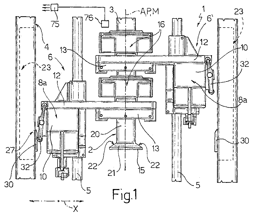
- Figures 1 and 2 show, with parts removed for clarity, schematic front and side views respectively of a forming unit in accordance with the present invention, for producing sealed packages from a tube of sheet packaging material filled with a pourable food product;
- Figures 3 and 4 show, with parts removed for clarity, enlarged rear-side views in perspective of a sealing jaw and a decoration correction device of the Figure 1-2 forming unit in two different operating configurations;
- Figure 5 shows a section in horizontal plane V-V in Figure 3;
- Figures 6 and 7 show larger-scale side views of a detail of the forming unit in the Figure 3 and 4 operating configurations respectively;
- Figure 8 shows a larger-scale cross section, with parts removed for clarity, of a portion of the sealing jaw in Figures 3 and 4.
-
-
Number 1 in Figure 1 indicates as a whole a forming unit for producing sealedpackages 2 from atube 3 of sheet packaging material having an axis A, filled with a pourable food product, and fed along a vertical path P parallel to axis A. - More specifically,
tube 3 is formed in known manner by longitudinally folding and sealing a web of packaging material, and is filled upstream fromunit 1 with the food product for packaging. - The web of packaging material has a multilayer structure (not shown), and conveniently comprises a layer of paper material covered on both sides with layers of heat-seal plastic material, e.g. polyethylene. In the case of aseptic packages for long-storage products, such as UHT milk, the packaging material comprises a layer of oxygen-barrier material defined, for example, by a sheet of aluminium, which is superimposed on a layer of heat-seal plastic material, and is in turn covered with another layer of heat-seal plastic material eventually defining the inner face of
packages 2 contacting the food product. - On the side eventually defining the outer surface of
packages 2, the web of packaging material has a succession of graphics or decorations (not shown) repeated at regular intervals with a given spacing. -
Unit 1 comprises a supportingstructure 4 defining twovertical guides 5, which are located symmetrically with respect to a central vertical longitudinal plane M ofunit 1 through axis A, and the axes of which lie in a central vertical transverse plane T ofunit 1, so that axis A defines the intersection of planes M and T. -
Unit 1 comprises in known manner two formingassemblies 6, 6' movable vertically alongrespective guides 5, and therefore along part of path P, and which interact cyclically and alternately withtube 3 of packaging material to grip and heat seal cross sections of the tube. - Since forming
assemblies 6, 6' are symmetrical with respect to plane M, only one (forming assembly 6) is shown in detail in Figures 2 to 8 and described below; and the corresponding parts of formingassemblies 6, 6' are indicated in Figure 1 using the same reference numbers. - As shown in Figures 1 and 2, forming
assembly 6 substantially comprises a slide 7 running alongrespective guide 5; and twojaws - The reciprocating movement of slides 7 and the opening/closing movement of
jaws - More specifically, each
jaw main control body 10 substantially in the form of a quadrangular plate extending along a work plane V (Figure 2) ofjaw respective control arm 11 projecting from the face ofbody 10 facing away from plane V, and activated, in known manner not shown, by one of said vertical rods. - Jaws 8a, 8b also comprise respective supporting
arms 12, which are fixed to the top ends ofrespective bodies 10, and project towards and beyond plane M, in a direction parallel to respective axes B and substantially along respective work planes V, so as to be located on opposite sides oftube 3. - The projecting portions of
arms 12 ofjaws tube 3, and which may be defined, for example, by an inductor for generating current in the aluminium layer of the packaging material to Joule-effect melt the thermoplastic layer, and by a pad for providing the back pressure required to griptube 3 to the required pressure. -
Jaws members 14grip tube 3, and a fully-open position. - At the transverse sealing stage,
tube 3 is heat sealed along equally spaced cross sections to formrespective sealing bands 15. -
Arms 12 ofjaws auxiliary bodies 13, withrespective shells 16 or so-called "volume boxes" for controlling the volume ofpackages 2 being formed, and which are only shown in Figures 1 and 2 and only described briefly insofar as necessary for a clear understanding of the present invention. - More specifically,
shells 16 are hinged at the bottom toarms 12 ofrespective jaws arms 12 by known elastic means not shown. -
Shells 16 have a C-shaped cross section open at the front, and, following transverse sealing by sealingmembers 14, cooperate with each other to define a cavity of given shape and volume, and which enclosestube 3 to form it into a rectangular-section configuration. - This forming stage produces
pillow packages 2 having amain portion 20 of a shape and volume corresponding to those of the finished packages, andtransition portions 21 defined laterally by substantiallytriangular faces 22 and connectingmain portion 20 to the respectiveadjacent sealing bands 15. - Forming
assembly 6 also comprises adevice 23 for adjusting the position of the decorations ontube 3 of packaging material with respect tojaws packages 2 issuing fromunit 1. -
Device 23 substantially comprises a pair oftraction members 25 fitted movably to one (8a) ofjaws tube 3 of packaging material in the direction of path P; and anadjustable cam assembly 26 for activatingtraction members 25 at a givenstation 27 along path P, and for adjusting the travel oftraction members 25 to control longitudinal feed oftube 3 throughunit 1. -
Traction members 25 are located on either side of and adjacent totube 3, and are symmetrical with respect to axis A. More specifically, traction members 25 (Figures 2 and 8) compriserespective pins 28 fitted in axially fixed and rotary manner through respective through holes formed inauxiliary body 13 ofjaw 8a and having axes D perpendicular to plane V; andrespective tabs 29 fitted eccentrically and integrally topins 28, and which interact with the packaging material oftube 3. - More specifically,
tabs 29 project from respective ends ofpins 28 facingtube 3, and so project fromrelative arm 12 ofjaw 8a on the same side as and above relative sealing member 14 (Figure 2), are curved with their concavities facing, and taper in section towardstube 3. - With reference to Figures 3 and 4,
cam assembly 26 comprises acam 30 fixed to anupright 31 of supportingstructure 4 and extending mainly vertically with an initial portion in the form of an oblique ramp; and acam follower member 32, which is fitted tojaw 8a, is connected totraction members 25, and cooperates in sliding manner withcam 30, as formingassembly 6 moves alongrelative guide 5, and therefore along path P, so as to be moved bycam 30 in a direction X perpendicular to path P and to plane M, and parallel to the extension direction ofarm 12 ofjaw 8a. - As described in detail later on,
traction members 25 are connected tocam follower member 32 by amechanism 33, which converts the movements in direction X ofcam follower member 32 into equal opposite rotations oftraction members 25 about respective axes D, so thattabs 29 are moved symmetrically with respect to path P. -
Cam 30 is defined by a contoured projection formed on a lateral face of a vertical parallelepiped-shapedblock 34 fixed toupright 31 and movable along a horizontal plane perpendicular to path P to adjust the position ofcam 30 in direction X. - The movements of
block 34 and, therefore, ofcam 30 along the horizontal plane are controlled, via amechanism 35, by a fluid-operatedlinear actuator 36 fitted to supportingstructure 4. - In the example shown,
actuator 36 is defined by two two-positionpneumatic cylinders mechanism 35 and a fixedmember 38 integral with supportingstructure 4. - More specifically,
cylinders respective jackets 39 fixed end to end, and inside which slide respective pistons, therods jackets 39 and are connected tomechanism 35 and fixedmember 38 respectively. -
Block 34, on whichcam 30 is formed, is supported between two, respectively top and bottom,plates upright 31. -
Mechanism 35 comprises a horizontal L-shapedlever 42 having one end hinged to the outwardly-projecting end ofrod 40a ofrelative cylinder 37a, and the opposite end fixed integrally to the top end of avertical rod 43, the bottom end of which extends in axially fixed and rotary manner throughplate 41a, and is fitted integrally, in an eccentric position, with acylindrical member 44 mounted to rotate inside a central vertical seat ofblock 34. The movement of one ofrods cylinders rod 43 about its axis, so that, given the eccentric connection ofrod 43 andblock 34,cam 30 moves along the horizontal plane, with a component in direction X. - A
leaf spring 45 extends vertically on one side ofblock 34, and has one end fixed toplate 41a, and an opposite free end pressing elastically against the opposite face ofblock 34 to that from which the cam projects, so as to keepblock 34 in a predetermined angular position with respect tocylindrical member 44. -
Actuator 36 is designed to enable, along axis E, three different operating positions of the projecting end ofrod 40a with respect to fixedmember 38, and which correspond to three different angular positions ofrod 43, and three possible settings ofcam 30 in direction X. - Alternatively,
actuator 36 may be defined by a pneumatic so-called "multistep" cylinder enabling three different operating positions of its output member. - According to a further possible embodiment,
actuator 36 may be defined by a powered cylinder defining a number of different operating positions. - As shown in Figures 3, 4, 6 and 7,
cam follower member 32 is defined by a rocker arm lever having anintermediate portion 50 connected, in rotary manner about an axis F perpendicular to axis A and to direction X, to asupport 51 fixed rigidly to and projecting frommain body 10 ofjaw 8a on the opposite side to that from whichrelative arm 12 projects; afirst end portion 52 fitted with anidle roller 53 cooperating in rolling manner withcam 30; and an oppositesecond end portion 54 connected bymechanism 33 totraction members 25. - More specifically,
cam follower member 32 projects fromsupport 51 and extends substantially vertically. -
Intermediate portion 50 ofcam follower member 32 is advantageously connected to support 51 by atoggle mechanism 55 crosswise tocam follower member 32, and which, by means of anactuator 56 also fitted to support 51, is movable selectively between an extended configuration of maximum length (Figures 3 and 6), whereincam follower member 32 is maintained in a work configuration, i.e. cooperating withcam 30, and a withdrawn configuration of minimum length (Figures 4 and 7), whereincam follower member 32 is maintained in a disabled configuration, i.e. detached fromcam 30. - In the example shown (Figures 6 and 7),
actuator 56 is defined by a pneumatic cylinder, and comprises ajacket 57 fixed to and projecting fromsupport 51 with its axis G parallel to axis A; and amovable member 58 mounted to slide axially insidejacket 57, and having an end portion projecting fromjacket 57 and connected to togglemechanism 55. -
Toggle mechanism 55 comprises twolevers movable member 58 and substantially parallel to direction X, and having adjacent ends hinged to each other and tomovable member 58, and opposite ends hinged to support 51 andintermediate portion 50 ofcam follower member 32 respectively. -
Movable member 58 is movable between a forward position of maximum extraction from jacket 57 (Figures 3 and 6), whereintoggle mechanism 55 is maintained in the extended configuration corresponding to the work configuration ofcam follower member 32, and a withdrawn position of minimum extraction fromjacket 57, whereintoggle mechanism 55 is maintained in the withdrawn configuration corresponding to the disabled configuration ofcam follower member 32. - With particular reference to Figures 6, 7 and 8,
mechanism 33 comprises arod 65 mounted to slide axially inside a longitudinal seat ofarm 12 ofjaw 8a, and having an end portion projecting from said seat and hinged to endportion 54 ofcam follower member 32; and atransmission mechanism 67, which is housed inside acavity 68 insideauxiliary body 13 ofjaw 8a and communicating with the above seat, and is interposed betweenrod 65 and pins 28 oftraction members 25. - More specifically,
transmission mechanism 67 comprises aplatelike lever 70, which is fixed integrally to an end portion ofrod 65 opposite the end portion hinged tocam follower member 32, is movable withrod 65 insidecavity 68 in a direction parallel to direction X, and defines two connectingportions respective arms traction members 25 and projecting radially from and fitted to respective pins 28. - More specifically,
lever 70 extends along a plane parallel to plane V, and forms different angles witharms rod 65 in direction X rotatestraction members 25 in opposite directions about respective axes D. -
Unit 1 is controlled by a known electronic central control unit 75 (shown schematically in Figure 1), which, by means of one or more optical sensors 76 (also shown schematically in Figure 1), determines the actual position of the decorations on the packaging material eventually formingpackages 2, compares the actual position with a theoretical reference position, and accordingly commandsactuator 36 of each formingassembly 6, 6' to adjust the position ofrelative cam 30 in direction X, and so adjust the pull to be exerted bytraction members 25. - In particular operating conditions,
central control unit 75 also commandsactuator 56, associated with each pair ofjaws cam follower member 32 between the work and disabled configurations by means ofrelative toggle mechanism 55. - More specifically, in the steady operating condition of
unit 1,movable member 58 of each actuator 56 is maintained in the forward position enabling interaction between eachcam 30 and relativecam follower member 32, and therefore operation oftraction members 25. - Conversely, when starting up
unit 1,movable member 58 of each actuator 56 is maintained in the withdrawn position preventing any interaction between eachcam 30 and relativecam follower member 32, and therefore betweentraction members 25 and theempty tube 3 of packaging material fed along path P. - Preferably,
movable member 58 of each actuator 56 is normally set to the withdrawn position (Figures 4 and 7), and is moved to the forward position bycentral control unit 75 activatingactuator 56. Alternatively,movable member 58 of each actuator 56 may be normally set to the forward position, and moved into the withdrawn position bycentral control unit 75 activatingactuator 56. - In actual use,
jaws assembly 6, 6' close as the assembly moves down, so as to griptube 3 with a downward vertical component of motion equal to the traveling speed oftube 3. More specifically,jaws assembly 6, 6' are brought together to gradually deformtube 3 and "flatten" it at a cross section or transverse band; at which point, sealingmembers 14 seal the two superimposed portions of packaging material forming the flat transverse band. - On nearing the bottom dead-center position of the downward travel of each forming
assembly 6, 6',jaws tube 3, and are opened completely as they move upwards and prior to reaching the top dead-center position of their upward travel. At this point,jaws - The movements of the two forming
assemblies 6, 6' are obviously offset by a half cycle : formingassembly 6 travels upwards withjaws jaws - In the steady operating condition of
unit 1,movable member 58 ofactuator 56 of eachjaw 8a is set to the forward position (Figures 3 and 6), in whichrelative toggle mechanism 55 is maintained in the extended configuration, and relativecam follower member 32 in the work configuration. As each formingassembly 6, 6' moves down,roller 53 ofcam follower member 32 ofrelative jaw 8a contacts the initial oblique-ramp portion of relative cam 30 (Figure 3), which divertsend portion 52 in direction X towardsjaw 8a. - Accordingly,
cam follower member 32 rotates about axis F, about which it is hinged torelative jaw 8a, so thatend portion 54 moves in direction X away fromjaw 8a, and drawsrod 65 in the same direction. - As shown by the arrows in Figure 8, by means of
arms rod 65 in direction X rotatestraction members 25 towards each other and downwards to exert a predetermined pull on the packaging material oftube 3. - When any difference is detected between the actual and reference positions of the decorations,
central control unit 75 commands actuator 36 of the formingassembly 6, 6' about to act ontube 3 to adjust the position ofrelative cam 30 in direction X, and so adjust the pull to be exerted ontube 3 byrelative traction members 25. - More specifically, activation of
actuator 36 rotatesrod 43 about its axis, so that, given the eccentric connection betweenrod 43 andblock 34,cam 30 moves along the horizontal plane with the desired component in direction X. - The above operation is repeated until the actual and reference positions of the decorations match.
- When starting up
unit 1,movable members 58 ofactuators 56 are set to the withdrawn positions (Figures 4 and 7) corresponding to the withdrawn configuration oftoggle mechanisms 55 and the disabled configuration of relativecam follower members 32. - As forming
assemblies 6, 6' move down, there is therefore no interaction betweencam follower members 32 andrelative cams 30, so thattraction members 25 remain idle. - Any interference between
traction members 25 and theempty tube 3 of packaging material fed along path P is therefore avoided, thus eliminating any risk of damage or impaired sterility oftube 3. - Clearly, changes may be made to
unit 1 as described herein without, however, departing from the scope of the accompanying Claims. - In particular,
unit 1 may comprise two series ofjaws tube 3, and cooperating cyclically with each other in pairs. In which case, each formingassembly 6, 6' would be defined by one jaw on one of the two conveyors, and by the corresponding jaw on the other conveyor.
Claims (9)
- A forming unit (1) for producing sealed packages (2) from a tube (3) of sheet packaging material fed along a feed path (P), filled with a pourable food product, and having a succession of equally spaced decorations; said unit (1) comprising jaw means (6, 6') movable cyclically along part of said path (P) to grip and seal said tube (3) of packaging material at equally spaced cross sections defining opposite sealing bands (15) of said packages (2), and an adjusting device (23) for adjusting the position of said decorations with respect to said jaw means (6, 6'); said adjusting device (23) comprising traction means (25) fitted movably to said jaw means (6, 6') and exerting pull on said tube (3) of packaging material to adjust feed of the tube along said path (P), and a cam assembly (26) for controlling and activating travel of said traction means (25) at a predetermined station (27) along said path (P); said cam assembly (26) comprising first interaction means (30) carried by fixed supporting means (31), and second interaction means (32) carried by said jaw means (6, 6'), connected to said traction means (25), and cooperating with said first interaction means (30) by virtue of the movement of said jaw means (6, 6') along said path (P); characterized by comprising actuating means (55, 56) activatable selectively to move said second interaction means (32) between a work configuration cooperating with said first interaction means (30), and a disabled configuration detached from said first interaction means (30).
- A unit as claimed in Claim 1, characterized in that said actuating means (55, 56) are so controlled as to move said second interaction means (32) into said disabled configuration when starting up said unit (1).
- A unit as claimed in Claim 1 or 2, characterized in that said first and second interaction means (30, 32) cooperate in a direction parallel to said path (P); and in that said actuating means comprise a toggle mechanism (55) extending crosswise to said path (P) and connecting said second interaction means (32) to said jaw means (6, 6'), and an actuator (56) for moving said toggle mechanism (55) between an extended configuration defining said work configuration of said second interaction means (32), and a withdrawn configuration defining said disabled configuration of said second interaction means (32).
- A unit as claimed in Claim 3, characterized in that said actuator (56) comprises an output member (58) movable in a direction (G) parallel to said path (P); and in that said toggle mechanism (55) comprises two levers (60, 61) having adjacent ends hinged to each other and to said output member (58) of said actuator (56), and opposite ends hinged to said jaw means (6, 6') and to said second interaction means (32) respectively.
- A unit as claimed in any one of the foregoing Claims, characterized in that said jaw means comprise at least two forming assemblies (6, 6'), each defined by two jaws (8a, 8b) cooperating cyclically with each other and with said tube (3); and in that said traction means (25), said actuating means (55, 56), and said second interaction means (32) are carried by one (8a) of said jaws (8a, 8b) of each said forming assembly (6, 6').
- A unit as claimed in any one of the foregoing Claims, characterized in that said first interaction means comprise a cam (30) extending mainly parallel to said path (P) with a ramplike initial portion, and fixed to said supporting means (31) in a position adjustable in a plane perpendicular to said path (P); said second interaction means comprising a cam follower member (32) cooperating in sliding manner with said cam (30) so as to be moved by the cam in a direction (X) crosswise to said path (P).
- A unit as claimed in Claim 6, characterized in that said cam follower member (32) is a rocker arm lever having an intermediate portion (50) hinged to said toggle mechanism (55), a first end portion (52, 53) cooperating with said cam (30), and a second end portion (54) connected to said traction means (25) by motion transmission means (33).
- A method of producing sealed packages (2), on a forming unit (1), from a tube (3) of sheet packaging material fed along a feed path (P), filled with a pourable food product, and having a succession of equally spaced decorations; said method comprising the steps of:characterized by also comprising the further step of selectively moving said second interaction means (32) between a work configuration cooperating with said first interaction means (30), and a disabled configuration detached from said first interaction means (30).moving jaw means (6, 6') of said forming unit (1) cyclically along part of said path (P) to grip and seal said tube (3) of packaging material at equally spaced cross sections defining opposite sealing bands (15) of said packages (2); andadjusting the position of said decorations with respect to said jaw means (6, 6') by exerting pull on said tube (3) to adjust feed of the tube along said path (P), and which is controlled by a cam assembly (26) comprising fixed first interaction means (30), and second interaction means (32) carried by said jaw means (6, 6') and cooperating with said first interaction means (30) by virtue of the movement of the jaw means (6, 6') along said path (P);
- A method as claimed in Claim 8, characterized in that said second interaction means (32) are moved into said disabled configuration when starting up said unit (1).
Priority Applications (4)
| Application Number | Priority Date | Filing Date | Title |
|---|---|---|---|
| ES03425073T ES2244911T3 (en) | 2003-02-10 | 2003-02-10 | TRAINING UNIT TO PRODUCE HERMETICALLY CLOSED CONTAINERS FROM A PACKING MATERIAL PIPE IN SHEETS FILLED WITH A FOOD PRODUCT THAT CAN BE VERTERED. |
| AT03425073T ATE297866T1 (en) | 2003-02-10 | 2003-02-10 | UNIT FOR PRODUCING SEALED PACKAGINGS OF FLOWABLE FOODS FROM TUBULAR PACKAGING MATERIAL |
| EP03425073A EP1445196B1 (en) | 2003-02-10 | 2003-02-10 | Forming unit for producing sealed packages from a tube of sheet packaging material filled with a pourable food product |
| DE60300857T DE60300857T2 (en) | 2003-02-10 | 2003-02-10 | Unit for producing sealed packages of flowable foodstuffs made of tubular packaging material |
Applications Claiming Priority (1)
| Application Number | Priority Date | Filing Date | Title |
|---|---|---|---|
| EP03425073A EP1445196B1 (en) | 2003-02-10 | 2003-02-10 | Forming unit for producing sealed packages from a tube of sheet packaging material filled with a pourable food product |
Publications (2)
| Publication Number | Publication Date |
|---|---|
| EP1445196A1 true EP1445196A1 (en) | 2004-08-11 |
| EP1445196B1 EP1445196B1 (en) | 2005-06-15 |
Family
ID=32605514
Family Applications (1)
| Application Number | Title | Priority Date | Filing Date |
|---|---|---|---|
| EP03425073A Expired - Lifetime EP1445196B1 (en) | 2003-02-10 | 2003-02-10 | Forming unit for producing sealed packages from a tube of sheet packaging material filled with a pourable food product |
Country Status (4)
| Country | Link |
|---|---|
| EP (1) | EP1445196B1 (en) |
| AT (1) | ATE297866T1 (en) |
| DE (1) | DE60300857T2 (en) |
| ES (1) | ES2244911T3 (en) |
Cited By (1)
| Publication number | Priority date | Publication date | Assignee | Title |
|---|---|---|---|---|
| EP2662291A1 (en) | 2012-05-11 | 2013-11-13 | Tetra Laval Holdings & Finance S.A. | Packaging unit and method for producing sealed packages |
Citations (3)
| Publication number | Priority date | Publication date | Assignee | Title |
|---|---|---|---|---|
| JPH11222212A (en) * | 1997-11-05 | 1999-08-17 | Tetra Laval Holdings & Finance Sa | Apparatus for modifying design of packaging machine for fluidal food |
| WO2000041932A1 (en) * | 1999-01-14 | 2000-07-20 | Tetra Laval Holdings & Finance S.A. | Device for aligning a packing material tube with a position mark |
| EP1162143A1 (en) * | 2000-06-06 | 2001-12-12 | Shikoku Kakoki Co., Ltd. | Web position matching system and packaging machine equipped with the system |
-
2003
- 2003-02-10 ES ES03425073T patent/ES2244911T3/en not_active Expired - Lifetime
- 2003-02-10 DE DE60300857T patent/DE60300857T2/en not_active Expired - Lifetime
- 2003-02-10 AT AT03425073T patent/ATE297866T1/en not_active IP Right Cessation
- 2003-02-10 EP EP03425073A patent/EP1445196B1/en not_active Expired - Lifetime
Patent Citations (3)
| Publication number | Priority date | Publication date | Assignee | Title |
|---|---|---|---|---|
| JPH11222212A (en) * | 1997-11-05 | 1999-08-17 | Tetra Laval Holdings & Finance Sa | Apparatus for modifying design of packaging machine for fluidal food |
| WO2000041932A1 (en) * | 1999-01-14 | 2000-07-20 | Tetra Laval Holdings & Finance S.A. | Device for aligning a packing material tube with a position mark |
| EP1162143A1 (en) * | 2000-06-06 | 2001-12-12 | Shikoku Kakoki Co., Ltd. | Web position matching system and packaging machine equipped with the system |
Non-Patent Citations (1)
| Title |
|---|
| PATENT ABSTRACTS OF JAPAN vol. 1999, no. 13 30 November 1999 (1999-11-30) * |
Cited By (4)
| Publication number | Priority date | Publication date | Assignee | Title |
|---|---|---|---|---|
| EP2662291A1 (en) | 2012-05-11 | 2013-11-13 | Tetra Laval Holdings & Finance S.A. | Packaging unit and method for producing sealed packages |
| WO2013167502A1 (en) | 2012-05-11 | 2013-11-14 | Tetra Laval Holdings & Finance S.A. | Packaging unit and method for producing sealed packages |
| JP2015516342A (en) * | 2012-05-11 | 2015-06-11 | テトラ・ラヴァル・ホールディングス・アンド・ファイナンス・ソシエテ・アノニムTetra Laval Holdings & Finance S.A. | Packaging unit and method for manufacturing a sealed package |
| US9284078B2 (en) | 2012-05-11 | 2016-03-15 | Tetra Laval Holdings & Finance S.A. | Packaging unit and method for producing sealed packages |
Also Published As
| Publication number | Publication date |
|---|---|
| ATE297866T1 (en) | 2005-07-15 |
| EP1445196B1 (en) | 2005-06-15 |
| ES2244911T3 (en) | 2005-12-16 |
| DE60300857T2 (en) | 2006-04-27 |
| DE60300857D1 (en) | 2005-07-21 |
Similar Documents
| Publication | Publication Date | Title |
|---|---|---|
| EP0992431B1 (en) | Method of producing sealed packages containing pourable food products from a tube of packing material, and packing unit implementing such a method | |
| EP2151390B1 (en) | Packaging method and unit for producing sealed packages of a food product pourable into a tube of packaging material | |
| EP1832518B1 (en) | Packaging machine for producing sealed packages of pourable food products | |
| EP1101700B1 (en) | Form and seal unit for a machine for packaging pourable food products | |
| EP3378792B1 (en) | Guiding device | |
| EP1172299B1 (en) | Machine for packaging pourable food products | |
| EP1509453B1 (en) | Forming jaw for producing a succession of sealed packages from a tube of sheet packaging material | |
| EP1325868A1 (en) | Packaging unit for continuously producing sealed packages, containing pourable food products, from a tube of packaging material | |
| EP1266832B1 (en) | Decoration correction method and system for a form-and-seal unit of a machine for packaging pourable food products | |
| EP1445196B1 (en) | Forming unit for producing sealed packages from a tube of sheet packaging material filled with a pourable food product | |
| EP0959007A1 (en) | Forming and sealing unit of a machine for packaging pourable food products | |
| EP1500594B1 (en) | Forming method and unit for producing sealed packages of pourable food products from a tube of sheet packaging material | |
| JP4190068B2 (en) | Design correction equipment for liquid food packaging machines | |
| EP3498616A1 (en) | A package forming unit for forming sealed packages | |
| RU2272759C2 (en) | Liquid food packing machine and method to control auxiliary means position on web | |
| EP3351478A1 (en) | Forming member for controlling the volume of packs of pourable food products formed from a tube of packaging material | |
| WO2000044624A1 (en) | Sealing jaws arrangement for packaging web material | |
| TW200415090A (en) | Forming unit for producing sealed packages from a tube of sheet packaging material filled with a pourable food product |
Legal Events
| Date | Code | Title | Description |
|---|---|---|---|
| PUAI | Public reference made under article 153(3) epc to a published international application that has entered the european phase |
Free format text: ORIGINAL CODE: 0009012 |
|
| 17P | Request for examination filed |
Effective date: 20040526 |
|
| AK | Designated contracting states |
Kind code of ref document: A1 Designated state(s): AT BE BG CH CY CZ DE DK EE ES FI FR GB GR HU IE IT LI LU MC NL PT SE SI SK TR |
|
| AX | Request for extension of the european patent |
Extension state: AL LT LV MK RO |
|
| GRAP | Despatch of communication of intention to grant a patent |
Free format text: ORIGINAL CODE: EPIDOSNIGR1 |
|
| GRAS | Grant fee paid |
Free format text: ORIGINAL CODE: EPIDOSNIGR3 |
|
| GRAA | (expected) grant |
Free format text: ORIGINAL CODE: 0009210 |
|
| AKX | Designation fees paid |
Designated state(s): AT BE BG CH CY CZ DE DK EE ES FI FR GB GR HU IE IT LI LU MC NL PT SE SI SK TR |
|
| AK | Designated contracting states |
Kind code of ref document: B1 Designated state(s): AT BE BG CH CY CZ DE DK EE ES FI FR GB GR HU IE IT LI LU MC NL PT SE SI SK TR |
|
| PG25 | Lapsed in a contracting state [announced via postgrant information from national office to epo] |
Ref country code: AT Free format text: LAPSE BECAUSE OF FAILURE TO SUBMIT A TRANSLATION OF THE DESCRIPTION OR TO PAY THE FEE WITHIN THE PRESCRIBED TIME-LIMIT Effective date: 20050615 Ref country code: NL Free format text: LAPSE BECAUSE OF FAILURE TO SUBMIT A TRANSLATION OF THE DESCRIPTION OR TO PAY THE FEE WITHIN THE PRESCRIBED TIME-LIMIT Effective date: 20050615 Ref country code: FI Free format text: LAPSE BECAUSE OF FAILURE TO SUBMIT A TRANSLATION OF THE DESCRIPTION OR TO PAY THE FEE WITHIN THE PRESCRIBED TIME-LIMIT Effective date: 20050615 Ref country code: SK Free format text: LAPSE BECAUSE OF FAILURE TO SUBMIT A TRANSLATION OF THE DESCRIPTION OR TO PAY THE FEE WITHIN THE PRESCRIBED TIME-LIMIT Effective date: 20050615 Ref country code: CZ Free format text: LAPSE BECAUSE OF FAILURE TO SUBMIT A TRANSLATION OF THE DESCRIPTION OR TO PAY THE FEE WITHIN THE PRESCRIBED TIME-LIMIT Effective date: 20050615 Ref country code: BE Free format text: LAPSE BECAUSE OF FAILURE TO SUBMIT A TRANSLATION OF THE DESCRIPTION OR TO PAY THE FEE WITHIN THE PRESCRIBED TIME-LIMIT Effective date: 20050615 Ref country code: EE Free format text: LAPSE BECAUSE OF FAILURE TO SUBMIT A TRANSLATION OF THE DESCRIPTION OR TO PAY THE FEE WITHIN THE PRESCRIBED TIME-LIMIT Effective date: 20050615 Ref country code: CH Free format text: LAPSE BECAUSE OF FAILURE TO SUBMIT A TRANSLATION OF THE DESCRIPTION OR TO PAY THE FEE WITHIN THE PRESCRIBED TIME-LIMIT Effective date: 20050615 Ref country code: TR Free format text: LAPSE BECAUSE OF FAILURE TO SUBMIT A TRANSLATION OF THE DESCRIPTION OR TO PAY THE FEE WITHIN THE PRESCRIBED TIME-LIMIT Effective date: 20050615 Ref country code: LI Free format text: LAPSE BECAUSE OF FAILURE TO SUBMIT A TRANSLATION OF THE DESCRIPTION OR TO PAY THE FEE WITHIN THE PRESCRIBED TIME-LIMIT Effective date: 20050615 Ref country code: SI Free format text: LAPSE BECAUSE OF FAILURE TO SUBMIT A TRANSLATION OF THE DESCRIPTION OR TO PAY THE FEE WITHIN THE PRESCRIBED TIME-LIMIT Effective date: 20050615 |
|
| REG | Reference to a national code |
Ref country code: CH Ref legal event code: EP Ref country code: GB Ref legal event code: FG4D |
|
| REF | Corresponds to: |
Ref document number: 60300857 Country of ref document: DE Date of ref document: 20050721 Kind code of ref document: P |
|
| REG | Reference to a national code |
Ref country code: IE Ref legal event code: FG4D |
|
| PG25 | Lapsed in a contracting state [announced via postgrant information from national office to epo] |
Ref country code: BG Free format text: LAPSE BECAUSE OF FAILURE TO SUBMIT A TRANSLATION OF THE DESCRIPTION OR TO PAY THE FEE WITHIN THE PRESCRIBED TIME-LIMIT Effective date: 20050915 Ref country code: DK Free format text: LAPSE BECAUSE OF FAILURE TO SUBMIT A TRANSLATION OF THE DESCRIPTION OR TO PAY THE FEE WITHIN THE PRESCRIBED TIME-LIMIT Effective date: 20050915 Ref country code: SE Free format text: LAPSE BECAUSE OF FAILURE TO SUBMIT A TRANSLATION OF THE DESCRIPTION OR TO PAY THE FEE WITHIN THE PRESCRIBED TIME-LIMIT Effective date: 20050915 Ref country code: GR Free format text: LAPSE BECAUSE OF FAILURE TO SUBMIT A TRANSLATION OF THE DESCRIPTION OR TO PAY THE FEE WITHIN THE PRESCRIBED TIME-LIMIT Effective date: 20050915 |
|
| PG25 | Lapsed in a contracting state [announced via postgrant information from national office to epo] |
Ref country code: PT Free format text: LAPSE BECAUSE OF FAILURE TO SUBMIT A TRANSLATION OF THE DESCRIPTION OR TO PAY THE FEE WITHIN THE PRESCRIBED TIME-LIMIT Effective date: 20051124 |
|
| NLV1 | Nl: lapsed or annulled due to failure to fulfill the requirements of art. 29p and 29m of the patents act | ||
| PG25 | Lapsed in a contracting state [announced via postgrant information from national office to epo] |
Ref country code: HU Free format text: LAPSE BECAUSE OF FAILURE TO SUBMIT A TRANSLATION OF THE DESCRIPTION OR TO PAY THE FEE WITHIN THE PRESCRIBED TIME-LIMIT Effective date: 20051216 |
|
| REG | Reference to a national code |
Ref country code: ES Ref legal event code: FG2A Ref document number: 2244911 Country of ref document: ES Kind code of ref document: T3 |
|
| REG | Reference to a national code |
Ref country code: CH Ref legal event code: PL |
|
| PG25 | Lapsed in a contracting state [announced via postgrant information from national office to epo] |
Ref country code: IE Free format text: LAPSE BECAUSE OF NON-PAYMENT OF DUE FEES Effective date: 20060210 |
|
| PG25 | Lapsed in a contracting state [announced via postgrant information from national office to epo] |
Ref country code: MC Free format text: LAPSE BECAUSE OF NON-PAYMENT OF DUE FEES Effective date: 20060228 Ref country code: LU Free format text: LAPSE BECAUSE OF NON-PAYMENT OF DUE FEES Effective date: 20060228 |
|
| ET | Fr: translation filed | ||
| PLBE | No opposition filed within time limit |
Free format text: ORIGINAL CODE: 0009261 |
|
| STAA | Information on the status of an ep patent application or granted ep patent |
Free format text: STATUS: NO OPPOSITION FILED WITHIN TIME LIMIT |
|
| 26N | No opposition filed |
Effective date: 20060316 |
|
| REG | Reference to a national code |
Ref country code: IE Ref legal event code: MM4A |
|
| GBPC | Gb: european patent ceased through non-payment of renewal fee |
Effective date: 20070210 |
|
| PG25 | Lapsed in a contracting state [announced via postgrant information from national office to epo] |
Ref country code: GB Free format text: LAPSE BECAUSE OF NON-PAYMENT OF DUE FEES Effective date: 20070210 |
|
| PG25 | Lapsed in a contracting state [announced via postgrant information from national office to epo] |
Ref country code: CY Free format text: LAPSE BECAUSE OF FAILURE TO SUBMIT A TRANSLATION OF THE DESCRIPTION OR TO PAY THE FEE WITHIN THE PRESCRIBED TIME-LIMIT Effective date: 20050615 |
|
| REG | Reference to a national code |
Ref country code: FR Ref legal event code: PLFP Year of fee payment: 14 |
|
| REG | Reference to a national code |
Ref country code: FR Ref legal event code: PLFP Year of fee payment: 15 |
|
| REG | Reference to a national code |
Ref country code: FR Ref legal event code: PLFP Year of fee payment: 16 |
|
| PGFP | Annual fee paid to national office [announced via postgrant information from national office to epo] |
Ref country code: ES Payment date: 20180305 Year of fee payment: 16 |
|
| PGFP | Annual fee paid to national office [announced via postgrant information from national office to epo] |
Ref country code: FR Payment date: 20180111 Year of fee payment: 16 |
|
| PGFP | Annual fee paid to national office [announced via postgrant information from national office to epo] |
Ref country code: DE Payment date: 20190129 Year of fee payment: 17 Ref country code: IT Payment date: 20190221 Year of fee payment: 17 |
|
| PG25 | Lapsed in a contracting state [announced via postgrant information from national office to epo] |
Ref country code: FR Free format text: LAPSE BECAUSE OF NON-PAYMENT OF DUE FEES Effective date: 20190228 |
|
| REG | Reference to a national code |
Ref country code: ES Ref legal event code: FD2A Effective date: 20200327 |
|
| PG25 | Lapsed in a contracting state [announced via postgrant information from national office to epo] |
Ref country code: ES Free format text: LAPSE BECAUSE OF NON-PAYMENT OF DUE FEES Effective date: 20190211 |
|
| REG | Reference to a national code |
Ref country code: DE Ref legal event code: R119 Ref document number: 60300857 Country of ref document: DE |
|
| PG25 | Lapsed in a contracting state [announced via postgrant information from national office to epo] |
Ref country code: DE Free format text: LAPSE BECAUSE OF NON-PAYMENT OF DUE FEES Effective date: 20200901 |
|
| PG25 | Lapsed in a contracting state [announced via postgrant information from national office to epo] |
Ref country code: IT Free format text: LAPSE BECAUSE OF NON-PAYMENT OF DUE FEES Effective date: 20200210 |