EP1445000A1 - Injection needle retractable injector - Google Patents
Injection needle retractable injector Download PDFInfo
- Publication number
- EP1445000A1 EP1445000A1 EP02780066A EP02780066A EP1445000A1 EP 1445000 A1 EP1445000 A1 EP 1445000A1 EP 02780066 A EP02780066 A EP 02780066A EP 02780066 A EP02780066 A EP 02780066A EP 1445000 A1 EP1445000 A1 EP 1445000A1
- Authority
- EP
- European Patent Office
- Prior art keywords
- hub
- tip
- needle base
- needle
- injection needle
- Prior art date
- Legal status (The legal status is an assumption and is not a legal conclusion. Google has not performed a legal analysis and makes no representation as to the accuracy of the status listed.)
- Withdrawn
Links
- 238000002347 injection Methods 0.000 title claims abstract description 121
- 239000007924 injection Substances 0.000 title claims abstract description 121
- 230000002093 peripheral effect Effects 0.000 claims abstract description 5
- 239000007788 liquid Substances 0.000 claims description 35
- 238000007789 sealing Methods 0.000 claims description 33
- 238000004519 manufacturing process Methods 0.000 description 12
- 238000000034 method Methods 0.000 description 11
- 239000000853 adhesive Substances 0.000 description 8
- 230000001070 adhesive effect Effects 0.000 description 5
- 230000000694 effects Effects 0.000 description 5
- 206010069803 Injury associated with device Diseases 0.000 description 3
- 230000008878 coupling Effects 0.000 description 3
- 238000010168 coupling process Methods 0.000 description 3
- 238000005859 coupling reaction Methods 0.000 description 3
- 230000006872 improvement Effects 0.000 description 3
- 238000003780 insertion Methods 0.000 description 3
- 230000037431 insertion Effects 0.000 description 3
- 230000000670 limiting effect Effects 0.000 description 3
- 238000000465 moulding Methods 0.000 description 3
- 230000002829 reductive effect Effects 0.000 description 3
- 238000006073 displacement reaction Methods 0.000 description 2
- 230000036961 partial effect Effects 0.000 description 2
- 238000003825 pressing Methods 0.000 description 2
- 230000009467 reduction Effects 0.000 description 2
- 238000000926 separation method Methods 0.000 description 2
- 238000007796 conventional method Methods 0.000 description 1
- 230000003247 decreasing effect Effects 0.000 description 1
- 230000007812 deficiency Effects 0.000 description 1
- 239000003814 drug Substances 0.000 description 1
- 229940079593 drug Drugs 0.000 description 1
- 230000007246 mechanism Effects 0.000 description 1
- 230000008569 process Effects 0.000 description 1
- 230000001105 regulatory effect Effects 0.000 description 1
- 238000007790 scraping Methods 0.000 description 1
- 239000000243 solution Substances 0.000 description 1
- 238000003860 storage Methods 0.000 description 1
- 230000003313 weakening effect Effects 0.000 description 1
Images





Classifications
-
- A—HUMAN NECESSITIES
- A61—MEDICAL OR VETERINARY SCIENCE; HYGIENE
- A61M—DEVICES FOR INTRODUCING MEDIA INTO, OR ONTO, THE BODY; DEVICES FOR TRANSDUCING BODY MEDIA OR FOR TAKING MEDIA FROM THE BODY; DEVICES FOR PRODUCING OR ENDING SLEEP OR STUPOR
- A61M5/00—Devices for bringing media into the body in a subcutaneous, intra-vascular or intramuscular way; Accessories therefor, e.g. filling or cleaning devices, arm-rests
- A61M5/178—Syringes
- A61M5/31—Details
- A61M5/32—Needles; Details of needles pertaining to their connection with syringe or hub; Accessories for bringing the needle into, or holding the needle on, the body; Devices for protection of needles
- A61M5/3205—Apparatus for removing or disposing of used needles or syringes, e.g. containers; Means for protection against accidental injuries from used needles
- A61M5/321—Means for protection against accidental injuries by used needles
- A61M5/322—Retractable needles, i.e. disconnected from and withdrawn into the syringe barrel by the piston
-
- A—HUMAN NECESSITIES
- A61—MEDICAL OR VETERINARY SCIENCE; HYGIENE
- A61M—DEVICES FOR INTRODUCING MEDIA INTO, OR ONTO, THE BODY; DEVICES FOR TRANSDUCING BODY MEDIA OR FOR TAKING MEDIA FROM THE BODY; DEVICES FOR PRODUCING OR ENDING SLEEP OR STUPOR
- A61M5/00—Devices for bringing media into the body in a subcutaneous, intra-vascular or intramuscular way; Accessories therefor, e.g. filling or cleaning devices, arm-rests
- A61M5/178—Syringes
- A61M5/31—Details
- A61M5/32—Needles; Details of needles pertaining to their connection with syringe or hub; Accessories for bringing the needle into, or holding the needle on, the body; Devices for protection of needles
- A61M5/3205—Apparatus for removing or disposing of used needles or syringes, e.g. containers; Means for protection against accidental injuries from used needles
- A61M5/321—Means for protection against accidental injuries by used needles
- A61M5/322—Retractable needles, i.e. disconnected from and withdrawn into the syringe barrel by the piston
- A61M5/3221—Constructional features thereof, e.g. to improve manipulation or functioning
- A61M2005/3231—Proximal end of needle captured or embedded inside piston head, e.g. by friction or hooks
-
- A—HUMAN NECESSITIES
- A61—MEDICAL OR VETERINARY SCIENCE; HYGIENE
- A61M—DEVICES FOR INTRODUCING MEDIA INTO, OR ONTO, THE BODY; DEVICES FOR TRANSDUCING BODY MEDIA OR FOR TAKING MEDIA FROM THE BODY; DEVICES FOR PRODUCING OR ENDING SLEEP OR STUPOR
- A61M5/00—Devices for bringing media into the body in a subcutaneous, intra-vascular or intramuscular way; Accessories therefor, e.g. filling or cleaning devices, arm-rests
- A61M5/178—Syringes
- A61M5/31—Details
- A61M5/32—Needles; Details of needles pertaining to their connection with syringe or hub; Accessories for bringing the needle into, or holding the needle on, the body; Devices for protection of needles
- A61M5/34—Constructions for connecting the needle, e.g. to syringe nozzle or needle hub
- A61M5/343—Connection of needle cannula to needle hub, or directly to syringe nozzle without a needle hub
-
- A—HUMAN NECESSITIES
- A61—MEDICAL OR VETERINARY SCIENCE; HYGIENE
- A61M—DEVICES FOR INTRODUCING MEDIA INTO, OR ONTO, THE BODY; DEVICES FOR TRANSDUCING BODY MEDIA OR FOR TAKING MEDIA FROM THE BODY; DEVICES FOR PRODUCING OR ENDING SLEEP OR STUPOR
- A61M5/00—Devices for bringing media into the body in a subcutaneous, intra-vascular or intramuscular way; Accessories therefor, e.g. filling or cleaning devices, arm-rests
- A61M5/178—Syringes
- A61M5/31—Details
- A61M5/32—Needles; Details of needles pertaining to their connection with syringe or hub; Accessories for bringing the needle into, or holding the needle on, the body; Devices for protection of needles
- A61M5/34—Constructions for connecting the needle, e.g. to syringe nozzle or needle hub
- A61M5/349—Constructions for connecting the needle, e.g. to syringe nozzle or needle hub using adhesive bond or glues
Definitions
- the present invention relates to a safe injection needle of a retractable injector type having a function for preventing accidental needlesticks. More specifically, it relates to an improvement of a fitting structure between a hub to which an injection needle is fixed and a needle base for attaching an injection needle to an injector tip part.
- Examples of an injector having a function for preventing accidental needlesticks include an injector having a configuration in which an injection needle is pulled into a barrel (outer cylinder) after use.
- This type of injector is disclosed in, for example, JP 7(1995)-51372A or JP 11(1999)-342200A.
- the injectors described in these documents have a mechanism for engaging a hub to which an injection needle is fixed with a plunger (inner cylinder) and allows the hub to engage the plunger after use, thereby pulling the injection needle into the barrel via the plunger.
- a liquid sealing property liquid shield performance
- a contacting portion between the outer surface of the hub and the inner surface of the needle base is made not to be a surface having a broad area that is long in the axial direction but a surface having a thin circular area in the axial direction that is approximately linear.
- a configuration is a negative factor from the viewpoint that the fitting strength increases as the contacting area is larger.
- Figure 6 shows one example of a cross-sectional shape of an injection needle attaching structure 21 constituting an injection needle retractable injector of a conventional example.
- the injection needle attaching structure 21 includes a hub 22, a needle base 23 and an injection needle 24.
- a tip part of the hub 22 is fitted to the rear part of a bore of the needle base 23; and a rear end part of the injection needle 24 is fixed to a tip part bore 22a of the hub 22.
- the bore of the needle base 23 includes a tip part bore 23a, a central part of a bore 23b and a rear part of a bore 23c. To the central part bore 23b, the tip part of the hub 22 is fitted and held.
- the hub 22 With the step formed at the boundary between the tip part bore 23a and the central part of a bore 23b, the hub 22 is restrained from moving toward the tip side and thus positioning is carried out
- the hub 22 has a pair of engaging legs 25 in the rear part, and each engaging leg 25 has a pulling protrusion 25a protruding outward is formed at the tip thereof.
- the injection needle attaching structure 21 is attached to the tip of a barrel (not shown) so as to construct an injector.
- the engaging legs 25 are located in the barrel.
- a plunger attached slidably in the barrel has an engaging portion capable of being engaged with the pulling protrusion 25a. Via the engagement, by the operation of extracting the plunger toward the rear side of the barrel, the hub 22 is pulled into the barrel.
- the tip of the injection needle 24 has to pass through the tip part bore 23a, and at this time, a needle edge may be damaged. Furthermore, the inner surface of the needle base 23 is scraped by the needle edge of the injection needle 23, and a burr, etc. (deep scraping or scraped residues) may be generated. Furthermore, since in general, injectors are manufactured by automatic assembly process, in order to insert the needle tip of the injection needle 24 into the inner surface of the needle base 23 without bringing it into contact with the inner surface, an automatic assembly device is required to have a considerable accuracy. For the above-mentioned reason, it is difficult to employ the above-mentioned method.
- a hub 22 is fitted into a needle base 23 and the fitted structure is supplied to the following step.
- the hub 22 is separated from the needle base 23 and moved in the direction of the rear side so as to form a state in which the tip of the hub 22 is exposed from the rear end of the needle base 23.
- the rear end part 24a of the injection needle 24 is inserted into the needle base 23 from the tip, and then, as shown in Figure 7C, the injection needle 24 is inserted into the tip part bore 22a of the hub 22 which is exposed from the rear end of the needle base 23.
- an adhesive 27 is applied to the tip part of the exposed hub 22 by using an adhesive applicator 26 positioned at the side part of the hub 22. Then, the hub 22 to which the injection needle 24 is fixed is moved toward the tip side of the needle base 23 and fitted to the central part bore 23b of the needle base 23. According to this method, since the injection needle 24 is inserted into the needle base 23 from the rear end part 24a, the damage of the needle edge of the injection needle 24 is avoided.
- the diameter of the tip part bore 23a is set to be larger than the outer diameter of the injection needle 24. Therefore, as shown in Figure 8, when a lateral force F1 is applied to the injection needle 24, the injection needle 24 swings in the lateral direction and is brought into contact with the tip part of the needle base 23. This contacting point works as a fulcrum 28, and thereby a lateral force F2 is applied from the rear end part 24a of the injection needle 24 to a fitting site 29 between the needle base 23 and the hub 22 in the central part bore 23b.
- an object of the present invention to provide an injection needle retractable injector that can be manufactured easily. It is also an object of the present invention to suppress the effect of an external force applied to the fitting between a hub and a needle base so as to maintain the fitting strength.
- the injection needle of the present invention includes: a barrel having a plunger inserted into a bore formed therein; a needle base attached to the tip part of the barrel; a hub attached to a bore of the needle base so as to be capable of being separated only toward the rear end side; and an injection needle with a rear end part fixed to the tip part of the hub.
- the plunger is capable of being moved to the tip part of the barrel to engage the rear end part of the hub with the tip part of the plunger, so that the injection needle can be pulled into the barrel through the plunger
- the hub is held in the needle base by a fitting structure formed between the outer peripheral surface of the tip part of the hub and the inner surface of the tip part of the needle base, and in the fitted state in which the hub is positioned at the closest to the tip side of the needle base, the tip of the hub is positioned near or forward of the tip of the needle base in the axial direction.
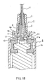
- Figure 1A is a cross-sectional view, partially abbreviated, showing an injection needle retractable injector according to one embodiment.
- Reference numeral 1 denotes an injection needle attachment structure and includes a hub 2 having a substantially cylindrical shape and being fitted to a bore of a substantially cylindrical shaped needle base 3; and an injection needle 4 fixed to the tip part of the hub 2.
- the hub 2 can be separated from the needle base 3 only toward the rear end side.
- This injection needle attachment structure 1 is attached to a barrel 5 so as to construct an injector by coupling the rear end part of the needle base 3 to the tip part of the substantially cylindrical-shaped barrel 5.
- Reference numeral 6 denotes a plunger inserted into the bore of the barrel 5.
- the plunger 6 includes a plunger main body 6a and a gasket 7.
- an inner wall 8 and an outer wall 9 are formed. Between the inner wall 8 and the outer wall 9, the rear end part of the needle base 3 is inserted. A latch part 9a formed on the inner side of the tip of the outer wall 9 is engaged with a coupling part 10 formed on the rear end of the needle base 3. Thereby, the attachment of the injection needle attachment structure 1 with respect to the barrel 5 is held.
- the hub 2 has engaging legs 11 at the rear end part.
- Each of the engaging legs 11 has a pulling protrusion 11a formed at the tip part and a holding protrusion 11b formed at the side part.
- the hub holding part 12 may be provided in the rear end part of the needle base 3.
- an engagement part 13 capable of engaging with the pulling protrusion 11a is provided.
- FIGs 1B and 1C show an operation of the injection needle retractable injector, respectively.
- the plunger 6 when the plunger 6 is moved to the front end of the barrel 5, the pulling protrusions 11a of the engaging legs 11 enter the engagement part 13 of the plunger main body 6a.
- the engaging legs 11 are engaged with the plunger main body 6a while the engaging legs 11 are deformed so as to release the engagement of the holding protrusion 11b and the hub holding portion 12. Therefore, as shown in Figure 1C, when the plunger 6 is moved toward the rear end side of the barrel 5, the hub 2 is released form the engagement with the needle base 3, and thereby the injection needle 4 can be pulled into the barrel 5.
- a state of preventing accidental needlesticks can be obtained.
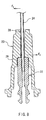
- Figure 2 is a cross-sectional view in the axial direction showing the injection needle attachment structure 1.
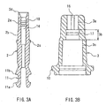
- Figure 3A is a cross-sectional view showing a hub 2
- Figure 3B is a cross-sectional view showing a needle base 3.
- the injection needle attachment structure 1 has a fitting structure formed on the outer surface of the tip part of the hub 2 and on the inner surface of the tip part of the needle base 3.
- the fitting structure includes a fitting maintaining region provided in the front part in the axial direction and a liquid sealing securing region provided in the rear part.
- the fitting maintaining region is formed by the outer surface of the tip part 2a of the hub and a tip part bore 3a of the needle base 3.
- the liquid sealing securing region is formed by the outer surface of the hub central part 2b and the central part of the bore 3b of the needle base 3.
- a base end of the injection needle 4 is inserted into a needle fixing bore 14 formed on the tip side of the hub 2 and fixed thereto with an adhesive 15.
- a position limiting protrusion 2c is provided on the rear end part of the hub 2 located in the rear part bore 3c of the needle base 3.
- the hub 2 is restrained from moving toward the tip side and thus the position is limited. Therefore, the hub 2 can be separated only toward the rear end side of the needle base 3.
- the tip 2d of the hub 2 is exposed from the tip of the needle base 3.
- the tip 2d of the hub may be recessed slightly from the tip end of the needle base 3.
- the hub tip 2d may be located in the vicinity of the tip of the needle base 3.
- the vicinity of the tip of the needle base 3 means the location approximating to the tip of the needle base 3 to such an extent that an adhesive applicator can be inserted easily. If in a condition of fitting the hub 2 and the needle base 3, the recessed amount of the tip 2d from the tip of the needle base 3 is within about 3 mm, it may be allowable practically.
- the tip 2d is protruded from the tip of the needle base 3, the allowable range of the above-mentioned meaning is not limited. However, the protruding amount is set appropriately in the range in which general use is not hindered.
- FIG. 3B on the inner surface of the tip part bore 3a of the needle base 3 forming a fitting maintaining region, longitudinal ribs 16 are formed.
- an annular protrusion 17 is formed in the inner surface of the central part bore 3b of the needle base 3 forming a liquid sealing securing region.
- Figure 2 shows a state in which the annular protrusion 17 is brought into contact with the outer surface of the hub 2.
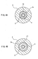
- Figure 4A is a cross-sectional view showing an enlarged section taken on line A-A of Figure 2.
- Figure 4B is a cross-sectional view showing an enlarged section taken on line B-B of Figure 2.
- three ribs 16 are provided in the peripheral direction and each of the ribs 16 is disposed at an equal interval.
- the outer surface of the hub central portion 2b forms a gentle taper in which the diameter is increased toward the rear side. Therefore, the contact between the needle base 3 and the hub 2 in the liquid sealing securing region is achieved between the annular protrusion 17 formed on the inner surface of the needle base 3 and the outer surface of the hub 2 on which taper is formed.
- This taper is formed only on the outer surface of the hub central part 2b but is not formed on the outer surface of the hub tip part 2a.
- a taper may be formed on the inner surface of the needle base 3 in the axial direction and the annular protrusion may be provided on the outer surface of the hub 2.
- the manufacturing process of the injection needle attachment structure 1 can be simplified.
- the allowance for insertion of the injection needle 4 is not required to be considered. This is because when the hub 2 and the needle base 3 are fitted to each other, the hub tip 2d is located in the vicinity of the tip of the needle base 3, therefore when the injection needle 4 is inserted into the hub 2, it is not brought into contact with the inner surface of the needle base 3.
- the base end 4a of the injection needle can be inserted directly into the needle fixing hole 14 seen from the hub tip 2d that is exposed from the tip of the needle base 3 or recessed slightly.
- the steps can be carried out easily.
- the injection needle 4 may not be inserted into the needle base 3, the accuracy required for automatically assembling apparatus can be alleviated and manufacturing process can be simplified.
- the injection needle base end 4a is inserted and fixed in the needle fixing hole 14 at the hub tip 2d
- the hub 2 with the injection needle is inserted into the needle base 3 from the rear side. That is to say the tip of the injection needle 4 is inserted from the rear end bore 3c, allowed to pass through the tip part bore 3a and to be exposed from the needle base 3.
- the hub 2 is pushed therein until the tip part 2a of the hub and the tip part bore 3a of the needle base 3 are fitted to each other.
- the hub 2 with the injection needle may be manufactured by a so-called insert molding, that is, by inserting the hub 2 at the time of molding.
- the maximum diameter of the injection needle 4 used for the retractable injector is 1.25 mm or less.
- the inner diameter of the inner wall 8 of the tip of the barrel is preferably in the range from 2.7 mm to 3.0 mm in order to enable the attachment to a general purpose injection needle.
- the preferable range of the outer diameter of the hub tip part 2a assumed from the maximum diameter of the injection needle 4 and the inner diameter of the inner wall 8 of the barrel tip is in the range from 2.2 mm to 2.9 mm.
- the preferable range of the outer diameter of the tip part bore 3a of the needle base 3, which is calculated from the range of the outer diameter of the hub tip part 2a is in the range from 2.25 mm to 2.95 mm. Therefore, the diameter of the tip part bore 3a is sufficiently larger than the maximum diameter of the injection needle 4.
- the diameter of the tip part bore 3a represents a diameter of the part in which the rib 16 is not formed.
- the diameter including the top part of the rib 16 is desired to be substantially the same or less of the outer diameter of the hub tip part 2a. Therefore, in the case where the rib 16 is not formed, the diameter of the tip part bore 3a is made to be substantially the same or less of the outer diameter of the hub tip part 2a.
- the fitting force between the needle base 3 and the hub 2 can be maintained effectively.
- Various factors are relevant to maintaining the fitting force. Among them, it is important to prevent rattling of the injection needle 4 due to the lateral swinging as described in the conventional example.
- the simplest method for solving the problem is to locate the fitting site of the hub 2 and the needle base 3 at the tip side of the needle base 3.
- the tip part of the needle base 3 works as a fulcrum
- the injection needle 4 swings it is found that if the fitting site is made dose to the tip of the needle base 3, the pressure to the fitting site caused by the lateral swing of the injection needle 4 can be decreased.
- the fitting maintaining region is formed by the outer surface of the hub tip part 2a and the tip part bore 3a of the needle base 3, the reduction in the fitting strength between the needle base 3 and the hub 2 can be suppressed effectively
- the above-mentioned configuration is effective in the improvement of the fitting force.
- the closeness at the fitting site between the needle base and the hub contributes much to improvement of the fitting force.
- the closeness at the fitting site herein denotes a state in which the needle base and the hub are brought into contact with each other securely so that the fitting site therebetween does not rattle.
- the diameter of the tip part bore 3a of the needle base 3 and the central part bore 3b are determined by considering only the fitting between the hub 2 and the outer surface. Therefore, rattling in fitting practically can be avoided by selecting, a dimension so that the hub 2 is brought into dose contact with the tip end bore 3a and the central part bore 3b.
- the contact between the needle base and the hub is not limited to the entire contact but may be a partial contact as long as secure contact state in each contacting point is obtained. Therefore, as shown in Figure 4A, a plurality of longitudinal linear ribs 16 may be formed on the inner surface of the needle base 3 so as to employ fitting obtained by the contact between these ribs 16 and the outer surface of the hub tip part 2a. This fitting does not provide a liquid sealing property but is efficient in obtaining the secure fitting force. As shown in Figure 4A, although an area of one of the ribs 16 that is brought into contact with the outer surface of the hub 2 is small, the outer surface of the hub 2 is uniformly held by three ribs 16 from the periphery, and thus sufficient fitting strength can be obtained. Furthermore, the fitting by the contact between the plurality of ribs formed in the axial direction and the outer surface of the hub can be operated more easily as compared with the fitting by the contact on the entire periphery.
- the number of ribs to be formed is preferably 2 to 4 when considering the cost, labor and effect into account.
- a protrusion or protruding portion having the other shapes may be formed in the inner surface of the tip part bore 3a forming the fitting maintaining region. Any protrusion or protruding portion having the other shape can exert the same effect as that of the ribs 16 as long as they cause appropriate pressure contact force between them and the outer surface of the hub tip part 2a.
- protrusions or protruding parts formed on the outer surface of the hub tip part 2a can provide the same function.
- the configuration of this embodiment is effective in coupling with both the fitting strength between the hub and the needle base and the liquid sealing property.
- each region can be constructed in an optimum structure.
- vertical linear ribs 16 are used for the fitting maintaining region and annular protrusion 17 is used for the liquid sealing securing region, thereby achieving both functions.
- annular protrusion 17 is used for the liquid sealing securing region, thereby achieving both functions.
- the fitting maintaining region and the liquid sealing securing region separately, the fitting maintaining region is configured so that a predetermined fitting strength is secured without considering the liquid sealing property and the liquid sealing securing region can be secured in a narrow annular region without considering the fitting strength.
- the fitting maintaining region is formed closer to the tip side of the needle base as compared with the liquid sealing securing region.
- the fitting site can be disposed in the needle base tip. side and the effect for maintaining the fitting force can be obtained efficiently.
- the liquid sealing property is maintained at rear end side of the needle base, dead volume of drug solution in the bore of the needle base in the injector can be reduced.
- the fitting maintaining region is located at 0 mm to 5 mm rear part from the tip end of the needle base in the axial direction of the injection needle.
- the fitting between the hub and the needle base preferably is obtained by the contact between the protruding shape formed on the inner surface of the needle base or the opposing surface.
- the fitting by the contact between the rib 16 formed on the inner surface of the needle base 3 and the annular protrusion 17 with respect to the outer surface of the hub 2 is efficient.
- the fitting site in the fitting maintaining region is located separately from the liquid sealing securing region and further a contacting area per protruding shape is small. Therefore, the fitting property in the fitting maintaining region has a small effect on the fitting state in the liquid sealing securing region with a low possibility of hindering the liquid sealing in the liquid sealing region.
- the tip side inner surface of the needle fixing hole 14 formed on the hub 2 is formed in a taper shape in which the inner diameter is increased toward the tip side so that the injection needle 4 can be inserted easily. Furthermore, near the tip of the needle fixing hole 14, two annular grooves 18 are engraved in order to hold the injection needle 4 more firmly. Furthermore, as mentioned above, on the outer surface of the hub central part 2b, a tapered portion for contacting annular protrusion is formed. The taper is formed in the range from 0 to 4.0 mm from the tip of the hub central part 2b. As mentioned above, the outer surface of the hub tip part 2a is a straight wall (not tapered). Furthermore, at the boundary between the outer surface of the hub tip part 2a and the outer surface of the hub central part 2b, a step is formed. The step together with the position limiting protrusion 2c prevents the hub 2 from moving to the tip side.
- the tip part bore 3a and central part bore 3b of the needle base 3 is regulated by the outer diameter of the hub 2 basically. However, since the outer surface of central part 2b of the hub is provides with a taper, the diameter is changed slightly along the axial direction.
- the rib 16 is formed in the location 1 to 5.0 mm distant from the tip of the needle base 3 in a longitudinal linear shape.
- the annular protrusion 17 is formed at the location 2 mm to 7 mm distant from the tip of the needle base 3 in the width of 0.3 mm to 3.0 mm.
- the rear part bore 3c of the needle base 3 is formed with a sufficiently large diameter, so that the hub 2 easily is inserted fiom the rear side.
- the fitting strength between the hub 2 and the needle base 3 is designed so that the force applied to the contacting part is in the range from 5 N/cm 2 to 15 N/cm 2 . In this range, the hub 2 and the needle base 3 are not likely to be accidentally separated from each other before use and after use, a user can release the fitting easily.
- the manufacturing process can be simplified and the cost can be reduced. Even in an automatic assembling apparatus, since the accuracy that was necessary to conventional methods is not required, a general-purposed apparatus can be used. Furthermore, a manufacturing method capable of protecting an edge of an injection needle can be applied.
- the fitting site between the hub and the needle base is located at the tip side of the needle base, it is possible to decrease the pressing force applied to the fitting site due to the lateral swinging of the injection needle.
- the reduction in the fitting strength between the needle base and the hub can be suppressed effectively, so that the fitting force can be maintained for a long time.
Landscapes
- Health & Medical Sciences (AREA)
- Engineering & Computer Science (AREA)
- Heart & Thoracic Surgery (AREA)
- Vascular Medicine (AREA)
- Anesthesiology (AREA)
- Biomedical Technology (AREA)
- Environmental & Geological Engineering (AREA)
- Hematology (AREA)
- Life Sciences & Earth Sciences (AREA)
- Animal Behavior & Ethology (AREA)
- General Health & Medical Sciences (AREA)
- Public Health (AREA)
- Veterinary Medicine (AREA)
- Infusion, Injection, And Reservoir Apparatuses (AREA)
Abstract
An injection needle retractable injector, comprising: a barrel
having a plunger inserted into a bore formed therein; a needle base
attached to the tip part of the barrel; a hub attached to a bore of the
needle base so as to be capable of being separated only toward the
rear end; and an injection needle with a rear end part fixed to the tip
part of the hub, the plunger being capable of being moved to the tip
part of the barrel to engage the rear end part of the hub with the tip
part of the plunger, so that the injection needle can be pulled into the
barrel through the plunger; wherein the hub is held in the needle
base by a fitting structure formed between the outer peripheral
surface of the tip part of the hub and the inner surface of the tip part
of the needle base, and in the fitted state in which the hub is
positioned at the closest to the tip side of the needle base, the tip of
the hub is positioned near or forward of the tip of the needle base in
the axial direction.
Description
The present invention relates to a safe injection needle of a retractable
injector type having a function for preventing accidental needlesticks. More
specifically, it relates to an improvement of a fitting structure between a hub to
which an injection needle is fixed and a needle base for attaching an injection
needle to an injector tip part.
Examples of an injector having a function for preventing accidental
needlesticks include an injector having a configuration in which an injection
needle is pulled into a barrel (outer cylinder) after use. This type of injector is
disclosed in, for example, JP 7(1995)-51372A or JP 11(1999)-342200A. The
injectors described in these documents have a mechanism for engaging a hub to
which an injection needle is fixed with a plunger (inner cylinder) and allows the
hub to engage the plunger after use, thereby pulling the injection needle into the
barrel via the plunger.
In the injector disclosed in JP11(1999)-342200A, in addition to an
appropriate fitting strength between a hub with an injection needle and a needle
base, a liquid sealing property (liquid shield performance) by the contact between
the outer surface of the hub and the inner surface of the needle base should be
maintained. In order to keep this liquid sealing property well, it is desirable that
a contacting portion between the outer surface of the hub and the inner surface of
the needle base is made not to be a surface having a broad area that is long in the
axial direction but a surface having a thin circular area in the axial direction that
is approximately linear. However, it is found that such a configuration is a
negative factor from the viewpoint that the fitting strength increases as the
contacting area is larger.
Furthermore, when the hub and the needle base are fitted to each other on
the linear contacting part as in the above-mentioned configuration, although a
predetermined fitting strength is kept at the time of manufacturing, the fitting
strength is likely to be reduced according to the state of transportation or storage,
and the risk of the hub being separated from the needle base is increased.
Therefore, in the structure of the above-mentioned injection needle retractable
injector, it is extremely difficult to provide and maintain both the liquid sealing
property and the fitting strength.
Furthermore, when a conventional injection needle retractable injector
such an injector as disclosed in JP11-342200A is manufactured, a problem that is
difficult to solve is caused as follows: Figure 6 shows one example of a
cross-sectional shape of an injection needle attaching structure 21 constituting an
injection needle retractable injector of a conventional example.
The injection needle attaching structure 21 includes a hub 22, a needle
base 23 and an injection needle 24. A tip part of the hub 22 is fitted to the rear
part of a bore of the needle base 23; and a rear end part of the injection needle 24 is
fixed to a tip part bore 22a of the hub 22. The bore of the needle base 23 includes
a tip part bore 23a, a central part of a bore 23b and a rear part of a bore 23c. To
the central part bore 23b, the tip part of the hub 22 is fitted and held. With the
step formed at the boundary between the tip part bore 23a and the central part of
a bore 23b, the hub 22 is restrained from moving toward the tip side and thus
positioning is carried out The hub 22 has a pair of engaging legs 25 in the rear
part, and each engaging leg 25 has a pulling protrusion 25a protruding outward is
formed at the tip thereof.
The injection needle attaching structure 21 is attached to the tip of a barrel
(not shown) so as to construct an injector. In this state, the engaging legs 25 are
located in the barrel. A plunger attached slidably in the barrel has an engaging
portion capable of being engaged with the pulling protrusion 25a. Via the
engagement, by the operation of extracting the plunger toward the rear side of the
barrel, the hub 22 is pulled into the barrel.
In the above-mentioned configuration, since the hub 22 has to be attached
to the needle base 23 from the rear end, a method of attaching the injection needle
24 and the hub 22 to the needle base 23 is limited. In general, firstly, it is thought
that the injection needle 24 is fixed to the hub 22, then the hub 22 with the
injection needle 24 is inserted into the needle base 23 from the rear end, and the
hub 22 is fitted to the needle base 23.
However, in this method, the tip of the injection needle 24 has to pass
through the tip part bore 23a, and at this time, a needle edge may be damaged.
Furthermore, the inner surface of the needle base 23 is scraped by the needle edge
of the injection needle 23, and a burr, etc. (deep scraping or scraped residues) may
be generated. Furthermore, since in general, injectors are manufactured by
automatic assembly process, in order to insert the needle tip of the injection needle
24 into the inner surface of the needle base 23 without bringing it into contact with
the inner surface, an automatic assembly device is required to have a considerable
accuracy. For the above-mentioned reason, it is difficult to employ the
above-mentioned method.
Therefore, in order to manufacture this injector, the steps shown in Figures
7A to 7C were required.
Firstly, as shown in Figure 7A, a hub 22 is fitted into a needle base 23 and
the fitted structure is supplied to the following step. Then, as shown in Figure
7B, before an injection needle 24 is attached to the hub 22, the hub 22 is separated
from the needle base 23 and moved in the direction of the rear side so as to form a
state in which the tip of the hub 22 is exposed from the rear end of the needle base
23. In this state, the rear end part 24a of the injection needle 24 is inserted into
the needle base 23 from the tip, and then, as shown in Figure 7C, the injection
needle 24 is inserted into the tip part bore 22a of the hub 22 which is exposed from
the rear end of the needle base 23. Then, an adhesive 27 is applied to the tip part
of the exposed hub 22 by using an adhesive applicator 26 positioned at the side
part of the hub 22. Then, the hub 22 to which the injection needle 24 is fixed is
moved toward the tip side of the needle base 23 and fitted to the central part bore
23b of the needle base 23. According to this method, since the injection needle 24
is inserted into the needle base 23 from the rear end part 24a, the damage of the
needle edge of the injection needle 24 is avoided.
However, as is apparent from Figures 7A to 7C, the above-mentioned
method has a complicated step and takes much time and labor. Furthermore, in
order to prevent separation of the injection needle 24 from the hub 22, or
contrarily, to prevent the generation of failure in fixing between the needle base 23
and the hub 22 due to excess adhesive agent, the accuracy in applying adhesives is
required so as to apply only to a predetermined region of the hub 22 without
excess and deficiency. Thus, this method also was difficult to apply to an
automatic assembly apparatus.
Furthermore, in the above-mentioned retractable injector, in order to
increase the insertion allowance (compliance) of the injection needle 24 with
respect to the tip part bore 23a of the needle base 23, the diameter of the tip part
bore 23a is set to be larger than the outer diameter of the injection needle 24.
Therefore, as shown in Figure 8, when a lateral force F1 is applied to the injection
needle 24, the injection needle 24 swings in the lateral direction and is brought
into contact with the tip part of the needle base 23. This contacting point works
as a fulcrum 28, and thereby a lateral force F2 is applied from the rear end part
24a of the injection needle 24 to a fitting site 29 between the needle base 23 and
the hub 22 in the central part bore 23b.
Even if the displacement of the injection needle 24 by the force F1 is small,
since the fitting site 29 between the hub 22 and the needle base 23 is distant from
the fulcrum 28, the displacement of the hub 22 due to force F2 in the fitting site 29
is increased. Therefore, rattling of the injection needle 24 at the tip part of the
needle base 23 becomes an important factor for weakening the fitting between the
hub 22 and the needle base 23. Thus, in the conventional retractable injectors,
due to the structure in which the fitting site 29 between the hub 22 and the needle
base 23 resides in the central part bore 23b that is in a deep place of the needle
base 23, and is distant from the tip of the needle base 23 that works as a fulcrum,
the fitting state between the hub 22 and the needle base 23 is difficult to be
maintained.
Therefore, it is an object of the present invention to provide an injection
needle retractable injector that can be manufactured easily. It is also an object of
the present invention to suppress the effect of an external force applied to the
fitting between a hub and a needle base so as to maintain the fitting strength.
The injection needle of the present invention includes: a barrel having a
plunger inserted into a bore formed therein; a needle base attached to the tip part
of the barrel; a hub attached to a bore of the needle base so as to be capable of
being separated only toward the rear end side; and an injection needle with a rear
end part fixed to the tip part of the hub. The plunger is capable of being moved to
the tip part of the barrel to engage the rear end part of the hub with the tip part of
the plunger, so that the injection needle can be pulled into the barrel through the
plunger In order to solve the above-mentioned problems, the hub is held in the
needle base by a fitting structure formed between the outer peripheral surface of
the tip part of the hub and the inner surface of the tip part of the needle base, and
in the fitted state in which the hub is positioned at the closest to the tip side of the
needle base, the tip of the hub is positioned near or forward of the tip of the needle
base in the axial direction.
Hereinafter, the embodiment of the present invention will be described
with reference to drawings. Figure 1A is a cross-sectional view, partially
abbreviated, showing an injection needle retractable injector according to one
embodiment.
Reference numeral 1 denotes an injection needle attachment structure and
includes a hub 2 having a substantially cylindrical shape and being fitted to a bore
of a substantially cylindrical shaped needle base 3; and an injection needle 4 fixed
to the tip part of the hub 2. The hub 2 can be separated from the needle base 3
only toward the rear end side. This injection needle attachment structure 1 is
attached to a barrel 5 so as to construct an injector by coupling the rear end part of
the needle base 3 to the tip part of the substantially cylindrical-shaped barrel 5.
Reference numeral 6 denotes a plunger inserted into the bore of the barrel 5. The
plunger 6 includes a plunger main body 6a and a gasket 7.
At the tip part of the barrel 5, an inner wall 8 and an outer wall 9 are
formed. Between the inner wall 8 and the outer wall 9, the rear end part of the
needle base 3 is inserted. A latch part 9a formed on the inner side of the tip of
the outer wall 9 is engaged with a coupling part 10 formed on the rear end of the
needle base 3. Thereby, the attachment of the injection needle attachment
structure 1 with respect to the barrel 5 is held.
The hub 2 has engaging legs 11 at the rear end part. Each of the engaging
legs 11 has a pulling protrusion 11a formed at the tip part and a holding
protrusion 11b formed at the side part. When the holding protrusion 11b is
engaged with the hub holding part 12 provided on the tip part of the barrel 5, the
hub 2 is restrained from moving toward the rear end side with respect to the
needle base 3. The hub holding part 12 may be provided in the rear end part of
the needle base 3. At the tip part of the plunger main body 6a, an engagement
part 13 capable of engaging with the pulling protrusion 11a is provided.
Figures 1B and 1C show an operation of the injection needle retractable
injector, respectively. As shown in Figure 1B, when the plunger 6 is moved to the
front end of the barrel 5, the pulling protrusions 11a of the engaging legs 11 enter
the engagement part 13 of the plunger main body 6a. Thus, the engaging legs 11
are engaged with the plunger main body 6a while the engaging legs 11 are
deformed so as to release the engagement of the holding protrusion 11b and the
hub holding portion 12. Therefore, as shown in Figure 1C, when the plunger 6 is
moved toward the rear end side of the barrel 5, the hub 2 is released form the
engagement with the needle base 3, and thereby the injection needle 4 can be
pulled into the barrel 5. By completely pulling the tip of the injection needle 4
into the barrel 5, a state of preventing accidental needlesticks can be obtained.
Then, the injection needle attachment structure 1 that is a characterizing
portion of the present invention will be described in detail. Figure 2 is a
cross-sectional view in the axial direction showing the injection needle attachment
structure 1. Figure 3A is a cross-sectional view showing a hub 2, and Figure 3B
is a cross-sectional view showing a needle base 3.
The injection needle attachment structure 1 has a fitting structure formed
on the outer surface of the tip part of the hub 2 and on the inner surface of the tip
part of the needle base 3. Thus, the hub 2 is held by the needle base 3. The
fitting structure includes a fitting maintaining region provided in the front part in
the axial direction and a liquid sealing securing region provided in the rear part.
The fitting maintaining region is formed by the outer surface of the tip part 2a of
the hub and a tip part bore 3a of the needle base 3. The liquid sealing securing
region is formed by the outer surface of the hub central part 2b and the central
part of the bore 3b of the needle base 3. A base end of the injection needle 4 is
inserted into a needle fixing bore 14 formed on the tip side of the hub 2 and fixed
thereto with an adhesive 15.
On the rear end part of the hub 2 located in the rear part bore 3c of the
needle base 3, a position limiting protrusion 2c is provided. When the position
limiting protrusion 2c is brought into contact with a step part formed on the
boundary of the central part bore 3b and the rear part bore 3c of the needle base 3,
the hub 2 is restrained from moving toward the tip side and thus the position is
limited. Therefore, the hub 2 can be separated only toward the rear end side of
the needle base 3. As shown in Figure 2, in a fitted state in which the hub 2 is
located nearest to the tip side, the tip 2d of the hub 2 is exposed from the tip of the
needle base 3.
The tip 2d of the hub may be recessed slightly from the tip end of the
needle base 3. In a word, the hub tip 2d may be located in the vicinity of the tip of
the needle base 3. The vicinity of the tip of the needle base 3 means the location
approximating to the tip of the needle base 3 to such an extent that an adhesive
applicator can be inserted easily. If in a condition of fitting the hub 2 and the
needle base 3, the recessed amount of the tip 2d from the tip of the needle base 3 is
within about 3 mm, it may be allowable practically. When the tip 2d is protruded
from the tip of the needle base 3, the allowable range of the above-mentioned
meaning is not limited. However, the protruding amount is set appropriately in
the range in which general use is not hindered.
As shown in Figure 3B, on the inner surface of the tip part bore 3a of the
needle base 3 forming a fitting maintaining region, longitudinal ribs 16 are
formed. In the inner surface of the central part bore 3b of the needle base 3
forming a liquid sealing securing region, an annular protrusion 17 is formed.
Figure 2 shows a state in which the annular protrusion 17 is brought into contact
with the outer surface of the hub 2. Furthermore, Figure 4A is a cross-sectional
view showing an enlarged section taken on line A-A of Figure 2. Figure 4B is a
cross-sectional view showing an enlarged section taken on line B-B of Figure 2.
As shown in Figure 4A, three ribs 16 are provided in the peripheral direction and
each of the ribs 16 is disposed at an equal interval.
In the configuration mentioned above, by pressing force between the three
ribs 16 and the outer surface of the hub tip part 2a, fitting of the hub 2 and the
needle base 3 is maintained substantially. Furthermore, due to a dose
attachment between the annular protrusion 17 and the outer surface of the hub
central part 2b, the liquid sealing between the needle base 3 and the hub 2 can be
secured.
The outer surface of the hub central portion 2b forms a gentle taper in
which the diameter is increased toward the rear side. Therefore, the contact
between the needle base 3 and the hub 2 in the liquid sealing securing region is
achieved between the annular protrusion 17 formed on the inner surface of the
needle base 3 and the outer surface of the hub 2 on which taper is formed. Thus,
it is possible to fit the needle base 3 with the hub 2 smoothly. That is to say, since
the annular protrusion 17 of the needle base 3 can slide smoothly on the tapered
outer surface of the hub 2, the liquid sealing property can be secured easily and
reliably. This taper is formed only on the outer surface of the hub central part 2b
but is not formed on the outer surface of the hub tip part 2a. Furthermore, if
necessary a taper may be formed on the inner surface of the needle base 3 in the
axial direction and the annular protrusion may be provided on the outer surface of
the hub 2.
An example of a method for manufacturing the injection needle
attachment structure having the above-mentioned configuration will be described
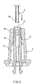
with reference to Figure 5. Firstly, the hub 2 is inserted from the rear side of the
needle base 3, so that the hub tip part 2a and the hub central part 2b are fitted to
the tip part bore 3a and the central part bore 3b of the needle base 3. Thus the
state shown in Figure 5 is achieved. Then, the injection needle base end 4a is
inserted into a needle fixing hole 14 of the hub tip 2d exposed from the tip of the
needle base 3 and fixed by using an adhesive agent 15 as shown in Figure 2.
Alternatively, without using the adhesive agent 15, fixing may be completed by
only inserting due to the fitting between the needle fixing hole 14 and the injection
needle proximal end 4a.
By using the above-mentioned configuration and manufacturing method,
the manufacturing process of the injection needle attachment structure 1 can be
simplified. The reason follows. Firstly, in the fitting structure between the hub
2 and the needle base 3 of the present invention, with respect to the tip part bore
3a and the central part of the bore 3b of the needle base 3, the allowance for
insertion of the injection needle 4 is not required to be considered. This is because
when the hub 2 and the needle base 3 are fitted to each other, the hub tip 2d is
located in the vicinity of the tip of the needle base 3, therefore when the injection
needle 4 is inserted into the hub 2, it is not brought into contact with the inner
surface of the needle base 3. When the injection needle 4 is embedded in the hub
2, as shown in Figure 5, the base end 4a of the injection needle can be inserted
directly into the needle fixing hole 14 seen from the hub tip 2d that is exposed from
the tip of the needle base 3 or recessed slightly. Thus, the steps can be carried out
easily. Furthermore, because the injection needle 4 may not be inserted into the
needle base 3, the accuracy required for automatically assembling apparatus can
be alleviated and manufacturing process can be simplified.
In the case of the injection needle attachment structure 1 having the
above-mentioned configuration, the following other manufacturing method can be
used Firstly, the injection needle base end 4a is inserted and fixed in the needle
fixing hole 14 at the hub tip 2d Next, the hub 2 with the injection needle is
inserted into the needle base 3 from the rear side. That is to say the tip of the
injection needle 4 is inserted from the rear end bore 3c, allowed to pass through
the tip part bore 3a and to be exposed from the needle base 3. Furthermore, the
hub 2 is pushed therein until the tip part 2a of the hub and the tip part bore 3a of
the needle base 3 are fitted to each other. The hub 2 with the injection needle
may be manufactured by a so-called insert molding, that is, by inserting the hub 2
at the time of molding. By attaching the hub 2 with injection needle produced by
the inset molding to the needle base 3, complicated steps shown in Figures 7A to
7C can be more simplified.
Such a simple method can be carried out assuming the structure in which
the hub tip part 2a is fitted to the tip part bore 3a of the needle base 3. The
reason follows. In order to obtain such a fitting structure, it is necessary that the
tip part bore 3a of the needle base 3 is substantially the same as the outer
diameter of the hub tip part 2a. As a result, the diameter of the tip part bore 3a
is larger than the outer diameter of the injection needle 4 by the dimension
corresponding to the wall thickness of the hub 2 and sufficiently larger than the
outer diameter of the injection needle 4. Therefore, when the injection needle 4 is
inserted into the bore of the needle base 3, the possibility of the inner surface of the
needle base 3 being damaged by the tip of the injection needle 4 is small. Thus,
the manufacturing method as mentioned above can be used easily.
For example, the maximum diameter of the injection needle 4 used for the
retractable injector is 1.25 mm or less. The inner diameter of the inner wall 8 of
the tip of the barrel is preferably in the range from 2.7 mm to 3.0 mm in order to
enable the attachment to a general purpose injection needle. The preferable
range of the outer diameter of the hub tip part 2a assumed from the maximum
diameter of the injection needle 4 and the inner diameter of the inner wall 8 of the
barrel tip is in the range from 2.2 mm to 2.9 mm. The preferable range of the
outer diameter of the tip part bore 3a of the needle base 3, which is calculated from
the range of the outer diameter of the hub tip part 2a is in the range from 2.25 mm
to 2.95 mm. Therefore, the diameter of the tip part bore 3a is sufficiently larger
than the maximum diameter of the injection needle 4.
Herein, the diameter of the tip part bore 3a represents a diameter of the
part in which the rib 16 is not formed. The diameter including the top part of the
rib 16 is desired to be substantially the same or less of the outer diameter of the
hub tip part 2a. Therefore, in the case where the rib 16 is not formed, the
diameter of the tip part bore 3a is made to be substantially the same or less of the
outer diameter of the hub tip part 2a.
According to the above-mentioned configuration of the injection needle
attachment structure 1, the fitting force between the needle base 3 and the hub 2
can be maintained effectively. Various factors are relevant to maintaining the
fitting force. Among them, it is important to prevent rattling of the injection
needle 4 due to the lateral swinging as described in the conventional example.
The simplest method for solving the problem is to locate the fitting site of the hub
2 and the needle base 3 at the tip side of the needle base 3. When considering
that the tip part of the needle base 3 works as a fulcrum, when the injection needle
4 swings, it is found that if the fitting site is made dose to the tip of the needle base
3, the pressure to the fitting site caused by the lateral swing of the injection needle
4 can be decreased. In the injection needle attachment structure 1, since the
fitting maintaining region is formed by the outer surface of the hub tip part 2a and
the tip part bore 3a of the needle base 3, the reduction in the fitting strength
between the needle base 3 and the hub 2 can be suppressed effectively
Furthermore, the above-mentioned configuration is effective in the
improvement of the fitting force. The closeness at the fitting site between the
needle base and the hub contributes much to improvement of the fitting force.
Unlike the liquid sealing, the closeness at the fitting site herein denotes a state in
which the needle base and the hub are brought into contact with each other
securely so that the fitting site therebetween does not rattle. As mentioned
above, in the fitting structure between the hub 2 and the needle base 3 of this
embodiment, with respect to the tip part bore 3a of the needle base 3 and the
central part bore 3b of the needle base 3, the allowance for insertion of the
injection needle 4 is not required to be considered. Consequently, the diameter of
the tip part bore 3a of the needle base 3 and the central part bore 3b are
determined by considering only the fitting between the hub 2 and the outer
surface. Therefore, rattling in fitting practically can be avoided by selecting, a
dimension so that the hub 2 is brought into dose contact with the tip end bore 3a
and the central part bore 3b.
The contact between the needle base and the hub is not limited to the
entire contact but may be a partial contact as long as secure contact state in each
contacting point is obtained. Therefore, as shown in Figure 4A, a plurality of
longitudinal linear ribs 16 may be formed on the inner surface of the needle base 3
so as to employ fitting obtained by the contact between these ribs 16 and the outer
surface of the hub tip part 2a. This fitting does not provide a liquid sealing
property but is efficient in obtaining the secure fitting force. As shown in Figure
4A, although an area of one of the ribs 16 that is brought into contact with the
outer surface of the hub 2 is small, the outer surface of the hub 2 is uniformly held
by three ribs 16 from the periphery, and thus sufficient fitting strength can be
obtained. Furthermore, the fitting by the contact between the plurality of ribs
formed in the axial direction and the outer surface of the hub can be operated
more easily as compared with the fitting by the contact on the entire periphery.
The number of ribs to be formed is preferably 2 to 4 when considering the
cost, labor and effect into account. Note here that in the inner surface of the tip
part bore 3a forming the fitting maintaining region, instead of longitudinal line
ribs 16, a protrusion or protruding portion having the other shapes may be
formed. Any protrusion or protruding portion having the other shape can exert
the same effect as that of the ribs 16 as long as they cause appropriate pressure
contact force between them and the outer surface of the hub tip part 2a.
Furthermore, such protrusions or protruding parts formed on the outer surface of
the hub tip part 2a can provide the same function.
Furthermore, the configuration of this embodiment is effective in coupling
with both the fitting strength between the hub and the needle base and the liquid
sealing property. In other words, since the fitting structure between the hub 2
and the needle base 3 is configured so as to be separated into the fitting
maintaining region and the liquid sealing securing region, each region can be
constructed in an optimum structure. In the above-mentioned configuration,
vertical linear ribs 16 are used for the fitting maintaining region and annular
protrusion 17 is used for the liquid sealing securing region, thereby achieving both
functions. Hereinafter, this will be described specifically.
In order to obtain a sufficient fitting strength, it is necessary to increase the
contact area in the entire fitting site. However, only the increase in the
contacting area of the fitting portion may hinder the liquid sealing property
between the hub and the needle base. Therefore, it is important to increase the
contact area of the fitting portion while the liquid sealing property is secured.
Therefore, sep aration of the fitting site is efficient. That it to say, by providing the
fitting maintaining region and the liquid sealing securing region separately, the
fitting maintaining region is configured so that a predetermined fitting strength is
secured without considering the liquid sealing property and the liquid sealing
securing region can be secured in a narrow annular region without considering the
fitting strength.
In the above-mentioned configuration, it is preferable that the fitting
maintaining region is formed closer to the tip side of the needle base as compared
with the liquid sealing securing region. Thus, as mentioned above, the fitting site
can be disposed in the needle base tip. side and the effect for maintaining the
fitting force can be obtained efficiently. Furthermore, since the liquid sealing
property is maintained at rear end side of the needle base, dead volume of drug
solution in the bore of the needle base in the injector can be reduced. It is
preferable that the fitting maintaining region is located at 0 mm to 5 mm rear part
from the tip end of the needle base in the axial direction of the injection needle.
It is possible to prevent the decrease of the fitting strength due to the force
applied via the injection needle mentioned above by providing a plurality of fitting
maintaining regions in the axial direction. At this time, providing too many
fitting sites, which are fitting maintaining region, is not significant, and
occasionally, the liquid sealing property may be damaged. The number of the
fitting sites is up to 2-3.
Furthermore, in order to increase the closeness of the fitting site without
lowering the liquid sealing property in the liquid securing region, the fitting
between the hub and the needle base preferably is obtained by the contact
between the protruding shape formed on the inner surface of the needle base or
the opposing surface. For example as shown in Figures 2, 3 and 4B, the fitting by
the contact between the rib 16 formed on the inner surface of the needle base 3
and the annular protrusion 17 with respect to the outer surface of the hub 2 is
efficient. With such a configuration, as mentioned above, although a contacting
area of one of the ribs is small, since a plurality of contacting sites are dispersed,
total fitness can be obtained sufficiently. Furthermore, the fitting site in the
fitting maintaining region is located separately from the liquid sealing securing
region and further a contacting area per protruding shape is small. Therefore,
the fitting property in the fitting maintaining region has a small effect on the
fitting state in the liquid sealing securing region with a low possibility of hindering
the liquid sealing in the liquid sealing region.
Then, referring to Figure 3, the shape and dimension of the hub 2 will be
described briefly. The tip side inner surface of the needle fixing hole 14 formed on
the hub 2 is formed in a taper shape in which the inner diameter is increased
toward the tip side so that the injection needle 4 can be inserted easily.
Furthermore, near the tip of the needle fixing hole 14, two annular grooves 18 are
engraved in order to hold the injection needle 4 more firmly. Furthermore, as
mentioned above, on the outer surface of the hub central part 2b, a tapered portion
for contacting annular protrusion is formed. The taper is formed in the range
from 0 to 4.0 mm from the tip of the hub central part 2b. As mentioned above,
the outer surface of the hub tip part 2a is a straight wall (not tapered).
Furthermore, at the boundary between the outer surface of the hub tip part 2a
and the outer surface of the hub central part 2b, a step is formed. The step
together with the position limiting protrusion 2c prevents the hub 2 from moving
to the tip side.
Next, shape and dimension of the needle base 3 will be described briefly.
The tip part bore 3a and central part bore 3b of the needle base 3 is regulated by
the outer diameter of the hub 2 basically. However, since the outer surface of
central part 2b of the hub is provides with a taper, the diameter is changed slightly
along the axial direction. The rib 16 is formed in the location 1 to 5.0 mm distant
from the tip of the needle base 3 in a longitudinal linear shape. The annular
protrusion 17 is formed at the location 2 mm to 7 mm distant from the tip of the
needle base 3 in the width of 0.3 mm to 3.0 mm. The rear part bore 3c of the
needle base 3 is formed with a sufficiently large diameter, so that the hub 2 easily
is inserted fiom the rear side.
It is preferable that the fitting strength between the hub 2 and the needle
base 3 is designed so that the force applied to the contacting part is in the range
from 5 N/cm2 to 15 N/cm2. In this range, the hub 2 and the needle base 3 are not
likely to be accidentally separated from each other before use and after use, a user
can release the fitting easily.
According to the injection needle retractable injector of the present
invention, since the tip of the hub is located in the vicinity of the needle base, the
manufacturing process can be simplified and the cost can be reduced. Even in an
automatic assembling apparatus, since the accuracy that was necessary to
conventional methods is not required, a general-purposed apparatus can be used.
Furthermore, a manufacturing method capable of protecting an edge of an
injection needle can be applied.
Furthermore, since the fitting site between the hub and the needle base is
located at the tip side of the needle base, it is possible to decrease the pressing
force applied to the fitting site due to the lateral swinging of the injection needle.
Thus, the reduction in the fitting strength between the needle base and the hub
can be suppressed effectively, so that the fitting force can be maintained for a long
time.
Claims (13)
- An injection needle retractable injector, comprising:wherein the hub is held in the needle base by a fitting structure formed between the outer peripheral surface of the tip part of the hub and the inner surface of the tip part of the needle base, and in the fitted state in which the hub is positioned at the closest to the tip side of the needle base, the tip of the hub is positioned near or forward of the tip of the needle base in the axial direction.a barrel having a plunger inserted into a bore formed therein;a needle base attached to the tip part of the barrel;a hub attached to a bore of the needle base so as to be capable of being separated only toward the rear end; andan injection needle with a rear end part fixed to the tip part of the hub,the plunger being capable of being moved to the tip part of the barrel to engage the rear end part of the hub with the tip part of the plunger, so that the injection needle can be pulled into the barrel through the plunger;
- An injection needle retractable injector, comprising:wherein the diameter of a tip part bore of the needle base is substantially the same as or larger than the outer diameter of the tip part of the hub, and smaller than the inner diameter of the tip part of the barrel, and in the fitted state in which the hub is positioned at the closest to the tip side of the needle base, the tip of the hub is positioned near or forward of the tip of the needle base in the axial direction.a barrel having a plunger inserted into a bore formed therein;a needle base attached to the tip part of the barrel;a hub attached to a bore of the needle base so as to be capable of being separated only toward the rear end; andan injection needle with a rear end part fixed to the tip part of the hub,the plunger being capable of being moved to the tip part of the barrel to engage the rear end part of the hub with the tip part of the plunger, so that the injection needle can be pulled into the barrel through the plunger;
- The injection needle retractable injector according to claim 1 or 2, wherein in the fitted state in which the hub is positioned at the closest to the tip side of the needle base, the tip of the hub is in substantially the same position as the tip of the needle base in the axial direction.
- The injection needle retractable injector according to claim 1 or 2, wherein in the fitted state in which the hub is positioned at the closest to the tip side of the needle base, the tip of the hub is exposed from the tip of the needle base or retracted from the tip of the needle base.
- The injection needle retractable injector according to claim 1 or 2, wherein the fitting structure is formed by the contact of the protruding shape formed on one of the inner surface of the needle base and the outer surface of the hub with the other opposing surface.
- The injection needle retractable injector according to claim 5, wherein the fitting structure comprises a fitting maintaining region and a liquid sealing securing region, which are provided separately, the fitting maintaining region has a function of maintaining the fitting between the needle base and the hub, and the liquid sealing securing region has a function for securing the liquid sealing property between the needle base and the hub.
- The injection needle retractable injector according to claim 6, wherein the fitting maintaining region is formed at a position closer to the tip side of the needle base than the liquid sealing securing region.
- The injection needle retractable injector according to claim 6 or 7, wherein the fitting structure in the fitting maintaining region is formed by the contact between a plurality of ribs formed in the longitudinal direction of the inner surface of the needle base and the outer surface of the hub.
- The injection needle retractable injector according to any one of claims 6 to 8, wherein the fitting structure in the liquid sealing securing region is formed by an annular protruding part formed on the inner surface of the needle base and a taper of the outer surface of the hub whose diameter becomes larger from the tip end to the rear end side in the axial direction; and the liquid sealing property is secured by the contact between the annular protruding portion and the outer surface of the hub.
- The injection needle retractable injector according to any one of claims 1 to 9, wherein the hub with an injection needle that was insert-molded is attached to the needle base.
- The injection needle retractable injector according to claim 1 or 2, wherein the hub has engaging legs at the rear end part, each engaging leg has a pulling protrusion formed at the tip part and holding protrusion formed at the side part, and the pulling protrusion can be engaged with the tip part of the plunger; when the holding protrusion is engaged with the tip part of the barrel or a hub holding part provided on the rear end part of the needle base, the hub is restrained form moving toward the rear end side of the needle base; and when the pulling protrusion is engaged with the tip part of the plunger, the engagement between the holding protrusion and the hub holding portion is released.
- The injection needle retractable injector according to claim 1, wherein force applied to a part where the hub and the needle base are brought into contact with each other is in the range from 5 N/cm2 to 15 N/cm2.
- An injection needle attachment structure for constructing an injection needle retractable injector comprising a hub attached to a bore of a needle base so as to be separated only toward the rear side, and an injection needle with a rear end part fixed to the tip part of the hub, wherein
the needle base can be attached to the tip part of a barrel having a plunger inserted into a bore formed therein;
the hub is provided with a pulling protrusion capable of engaging with the tip part of the plunger at the rear end part;
the hub is held by the needle base by a fitting structure formed between the tip part outer peripheral surface of the hub and the inner surface of the tip part of the needle base, and in the fitted state in which the hub is positioned at the closest to the tip side of the needle base, the tip part of the hub is positioned in the vicinity or forward of the tip of the needle base in axial direction.
Applications Claiming Priority (3)
| Application Number | Priority Date | Filing Date | Title |
|---|---|---|---|
| JP2001346025 | 2001-11-12 | ||
| JP2001346025 | 2001-11-12 | ||
| PCT/JP2002/011714 WO2003041771A1 (en) | 2001-11-12 | 2002-11-11 | Injection needle retractable injector |
Publications (1)
| Publication Number | Publication Date |
|---|---|
| EP1445000A1 true EP1445000A1 (en) | 2004-08-11 |
Family
ID=19159264
Family Applications (1)
| Application Number | Title | Priority Date | Filing Date |
|---|---|---|---|
| EP02780066A Withdrawn EP1445000A1 (en) | 2001-11-12 | 2002-11-11 | Injection needle retractable injector |
Country Status (4)
| Country | Link |
|---|---|
| US (1) | US20040267209A1 (en) |
| EP (1) | EP1445000A1 (en) |
| TW (1) | TW200300354A (en) |
| WO (1) | WO2003041771A1 (en) |
Cited By (4)
| Publication number | Priority date | Publication date | Assignee | Title |
|---|---|---|---|---|
| EP1754499A1 (en) * | 2005-08-19 | 2007-02-21 | Wei-Shui Wu | Safety hypodermic syringe with retractable needle carrier |
| CN102553029A (en) * | 2011-10-09 | 2012-07-11 | 李慧慧 | Sealing structure of disposable safe syringe needle seat |
| CN103945884A (en) * | 2011-11-09 | 2014-07-23 | 尤尼特拉克特注射器公司 | Improved retractable syringe needle |
| EP3047869A1 (en) * | 2015-01-23 | 2016-07-27 | Sanofi-Aventis Deutschland GmbH | Needle assembly with needle coupling for snap fit on hub |
Families Citing this family (10)
| Publication number | Priority date | Publication date | Assignee | Title |
|---|---|---|---|---|
| JP5169218B2 (en) * | 2005-09-13 | 2013-03-27 | ニプロ株式会社 | Syringe |
| EP2049110B1 (en) * | 2006-07-14 | 2014-08-20 | Merck Sharp & Dohme Corp. | Bridged diazepan orexin receptor antagonists |
| WO2008152849A1 (en) * | 2007-06-12 | 2008-12-18 | Terumo Kabushiki Kaisha | Method of producing indwelling needle assembly and indwelling needle assembly |
| US8157816B2 (en) | 2007-08-31 | 2012-04-17 | Kimberly-Clark Worldwide, Inc. | Gastropexy kit |
| CN201194975Y (en) * | 2008-02-25 | 2009-02-18 | 周令刚 | Safety self-breaking syringe |
| NZ600456A (en) * | 2009-11-11 | 2014-06-27 | Unitract Syringe Pty Ltd | Vaccination syringe |
| US10098628B2 (en) | 2014-07-22 | 2018-10-16 | Cook Medical Technologies Llc | Anchor deployment system, device, and method of treatment |
| CN114173941B (en) * | 2019-08-02 | 2023-06-09 | 诺信公司 | Dispensing tip and method of manufacturing a dispensing tip |
| CN113616880A (en) * | 2020-05-09 | 2021-11-09 | 苏州德奇汽车配件系统有限公司 | Self-destruction disposable syringe |
| JP2025541327A (en) * | 2022-12-13 | 2025-12-18 | ヘキシリス インコーポレイテッド | Medical devices and ocular implants for the treatment of eye disorders |
Family Cites Families (8)
| Publication number | Priority date | Publication date | Assignee | Title |
|---|---|---|---|---|
| US4898589A (en) * | 1988-03-09 | 1990-02-06 | Stuart M. Dolgin | Fluid passing apparatus with means for covering the same |
| AU616711B2 (en) * | 1987-12-21 | 1991-11-07 | Stuart M. Dolgin | Fluid passing apparatus with means for covering the same |
| US5098402A (en) * | 1990-05-23 | 1992-03-24 | Davis Lynn E | Retractable hypodermic syringe |
| ATE156712T1 (en) * | 1993-07-26 | 1997-08-15 | Finestyle Properties Limited | DISPOSABLE SYRINGE WITH RETRACTABLE NEEDLE |
| JP3044544U (en) * | 1997-06-18 | 1997-12-22 | 文能 劉 | Syringe |
| JPH11342200A (en) * | 1997-11-26 | 1999-12-14 | Agifin Srl | Throw-away type injector |
| US6093171A (en) * | 1999-12-30 | 2000-07-25 | Huang; Wu-Shun | Safety syringe |
| TWI242456B (en) * | 2001-02-06 | 2005-11-01 | Jms Co Ltd | Syringe for medical use |
-
2002
- 2002-11-08 TW TW091132968A patent/TW200300354A/en unknown
- 2002-11-11 EP EP02780066A patent/EP1445000A1/en not_active Withdrawn
- 2002-11-11 US US10/495,175 patent/US20040267209A1/en not_active Abandoned
- 2002-11-11 WO PCT/JP2002/011714 patent/WO2003041771A1/en not_active Ceased
Non-Patent Citations (1)
| Title |
|---|
| See references of WO03041771A1 * |
Cited By (9)
| Publication number | Priority date | Publication date | Assignee | Title |
|---|---|---|---|---|
| EP1754499A1 (en) * | 2005-08-19 | 2007-02-21 | Wei-Shui Wu | Safety hypodermic syringe with retractable needle carrier |
| CN102553029A (en) * | 2011-10-09 | 2012-07-11 | 李慧慧 | Sealing structure of disposable safe syringe needle seat |
| CN102553029B (en) * | 2011-10-09 | 2013-06-26 | 李慧慧 | Sealing structure of disposable safe syringe needle seat |
| CN103945884A (en) * | 2011-11-09 | 2014-07-23 | 尤尼特拉克特注射器公司 | Improved retractable syringe needle |
| EP2776097A4 (en) * | 2011-11-09 | 2015-05-27 | Unitract Syringe Pty Ltd | Improved retractable syringe needle |
| AU2012334816B2 (en) * | 2011-11-09 | 2016-03-10 | Unitract Syringe Pty Ltd | Improved retractable syringe needle |
| US9604010B2 (en) | 2011-11-09 | 2017-03-28 | Unitract Syringe Pty Ltd | Retractable syringe needle |
| CN103945884B (en) * | 2011-11-09 | 2017-04-05 | 尤尼特拉克特注射器公司 | Improved retractable syringe needle |
| EP3047869A1 (en) * | 2015-01-23 | 2016-07-27 | Sanofi-Aventis Deutschland GmbH | Needle assembly with needle coupling for snap fit on hub |
Also Published As
| Publication number | Publication date |
|---|---|
| TW200300354A (en) | 2003-06-01 |
| US20040267209A1 (en) | 2004-12-30 |
| WO2003041771A1 (en) | 2003-05-22 |
Similar Documents
| Publication | Publication Date | Title |
|---|---|---|
| US20040267209A1 (en) | Injection needle retractable injector | |
| CN101467926B (en) | Intraocular lens insertion tool | |
| JP2001336515A (en) | Clip | |
| EP2000164A1 (en) | Self-destroying disposable syringe and self-destroying method thereof | |
| KR101673737B1 (en) | Clip | |
| AU2016384940B2 (en) | Safe syringe | |
| RU2009109943A (en) | SAFE MEDICAL SYRINGE | |
| US7377911B2 (en) | Medical needle device with winged shield for erroneous piercing prevention | |
| US20090062736A1 (en) | Safety syringe assembly | |
| US20030093038A1 (en) | Needle retraction type safety syringe | |
| CA2463410C (en) | Medical needle device having winged shield for preventing accidental needlestick | |
| JP2003205035A (en) | Needle retractable syringe | |
| US6409703B1 (en) | Safety syringe for intravenous injection | |
| CN220588694U (en) | Rectangular automatic injection pen | |
| EP1364668A1 (en) | Safe injector and injection needle for safe injector | |
| US20060229554A1 (en) | Mechanism for tilting retractable needle | |
| US20250099688A1 (en) | Needle tip protector | |
| KR20170137849A (en) | Guide lens insertion mechanism | |
| JP2006255272A (en) | Disposable safety syringe | |
| WO2001064272A1 (en) | Retractable non-reusable syringe | |
| KR102000669B1 (en) | Disposable syringe | |
| JP7470306B2 (en) | Puncture needle with protector | |
| CN223054623U (en) | Glaucoma drainage tube implantation device and implantation assembly | |
| EP3159029B1 (en) | Liquid injector for continuously injecting fixed quantity of charged liquid | |
| JP4736049B2 (en) | Syringe |
Legal Events
| Date | Code | Title | Description |
|---|---|---|---|
| PUAI | Public reference made under article 153(3) epc to a published international application that has entered the european phase |
Free format text: ORIGINAL CODE: 0009012 |
|
| 17P | Request for examination filed |
Effective date: 20040513 |
|
| AK | Designated contracting states |
Kind code of ref document: A1 Designated state(s): AT BE BG CH CY CZ DE DK EE ES FI FR GB GR IE IT LI LU MC NL PT SE SK TR |
|
| AX | Request for extension of the european patent |
Extension state: AL LT LV MK RO SI |
|
| STAA | Information on the status of an ep patent application or granted ep patent |
Free format text: STATUS: THE APPLICATION HAS BEEN WITHDRAWN |
|
| 18W | Application withdrawn |
Effective date: 20060524 |