EP1444909A1 - Boots liner - Google Patents
Boots liner Download PDFInfo
- Publication number
- EP1444909A1 EP1444909A1 EP04001804A EP04001804A EP1444909A1 EP 1444909 A1 EP1444909 A1 EP 1444909A1 EP 04001804 A EP04001804 A EP 04001804A EP 04001804 A EP04001804 A EP 04001804A EP 1444909 A1 EP1444909 A1 EP 1444909A1
- Authority
- EP
- European Patent Office
- Prior art keywords
- strap
- parts
- boot liner
- boot
- rear portion
- Prior art date
- Legal status (The legal status is an assumption and is not a legal conclusion. Google has not performed a legal analysis and makes no representation as to the accuracy of the status listed.)
- Granted
Links
- 210000003423 ankle Anatomy 0.000 claims abstract description 40
- 238000003780 insertion Methods 0.000 claims abstract description 35
- 230000037431 insertion Effects 0.000 claims abstract description 35
- 210000002683 foot Anatomy 0.000 claims description 13
- 230000035807 sensation Effects 0.000 abstract description 11
- 230000000694 effects Effects 0.000 description 4
- 230000002093 peripheral effect Effects 0.000 description 2
- 230000000452 restraining effect Effects 0.000 description 2
- 238000010521 absorption reaction Methods 0.000 description 1
- 238000012986 modification Methods 0.000 description 1
- 230000004048 modification Effects 0.000 description 1
- 230000035939 shock Effects 0.000 description 1
Images


Classifications
-
- A—HUMAN NECESSITIES
- A43—FOOTWEAR
- A43B—CHARACTERISTIC FEATURES OF FOOTWEAR; PARTS OF FOOTWEAR
- A43B19/00—Shoe-shaped inserts; Inserts covering the instep
-
- A—HUMAN NECESSITIES
- A43—FOOTWEAR
- A43B—CHARACTERISTIC FEATURES OF FOOTWEAR; PARTS OF FOOTWEAR
- A43B5/00—Footwear for sporting purposes
- A43B5/04—Ski or like boots
- A43B5/0405—Linings, paddings or insertions; Inner boots
-
- A—HUMAN NECESSITIES
- A43—FOOTWEAR
- A43C—FASTENINGS OR ATTACHMENTS OF FOOTWEAR; LACES IN GENERAL
- A43C1/00—Shoe lacing fastenings
Definitions
- the present invention generally relates to a boot liner. More specifically, the present invention relates to an inner boot liner for a snowboard boot.
- Ski boots, snowboard boots, and other such thermal footwear products generally comprise an outer boot disposed on the outside and a boot liner (inner boot) disposed on the inside of the outer boot.
- boot liner inner boot
- boot liners are configured in a shape and a material so as to provide warmth to the wearer's feet, shock absorption, good foot comfort, and the like.
- Boot liners generally comprise a sole forming the bottom portion of the boot and an upper part formed extending over the top of the sole so as to cover the foot and ankle of the wearer.
- the upper part has a rear portion for supporting the rear section of the ankle, and a pair of side parts that support the side sections of the ankle and are integrally formed with the rear portion.
- the front ends are disposed separated from each other, and a slit is formed in the front section of the ankle.
- a tongue for supporting the front section of the ankle is fitted extending to the top in the bottom end of the slit (for example, see UK Patent No. 5924218).
- Examples of this type of conventional boot liner include those that further comprise a fastening mechanism for improving the perceived fit of the upper part on the foot.
- the fastening mechanism normally has a plurality of insertion elements disposed in the vicinity of the front end of the upper part at intervals in the vertical direction. Each insertion element is formed in a loop shape so that a shoelace or other such lace-shaped member can be inserted (for example, see UK Patent No. 5937542).
- the ends of the shoelace are inserted in a pair of insertion elements at the same vertically aligned positions, the ends are intersected while being pulled so that the front ends move closer to each other, the operation of inserting them into adjacent insertion elements in the front end at opposite sides is repeated, and the ends are then tied together and fixed to each other, whereby the upper part is pressed against the wearer's foot, and a specific sensation of fitting is obtained.
- the deformation of the upper part is limited to a condition in which the front ends merely come closer to each other when fastened to the ankle of the wearer, for which reason the sensation of fitting on the ankle is sometimes insufficient.
- One object of the present invention is to provide a boot liner wherein the sensation of the upper part fitting on the ankle can be adequately obtained.
- a boot liner that basically comprises a sole, an upper part, and a fastening mechanism.
- the upper part is coupled to the sole to extend over the sole to form a foot receiving space.
- the upper part includes a rear portion configured and arranged to support a rear area of a wearer's ankle, and a pair of side parts formed integrally with the rear portion to support side sections of the ankle.
- the side parts of the upper part both have front ends facing each other at the front of the ankle.
- the fastening mechanism is a mechanism that is coupled to the upper part and configured and arranged to tighten the upper part about the wearer's ankle.
- the fastening mechanism comprises a main strap member.
- This main strap member has a first fixed strap part, a pair of movable strap parts, and a second fixed strap part.
- the first fixed strap part are fixed to the rear portion of the upper part and extend generally in a horizontal direction.
- the pair of movable strap parts extend generally forward from forward ends of the first fixed strap part along side surfaces of the upper part.
- the pair of movable strap parts are folded back to form a pair of insertion elements in the vicinity of the front ends of the upper part wherein lace-shaped members can be inserted.
- the pair of movable strap parts are moveable in relation to the upper part such that the movable strap parts extend from the insertion elements along one of the side surfaces to an opposite side of the side surfaces with the movable strap parts intersecting each other at the rear portion.
- the pair of second fixed strap parts are fixed to at least one of the sole and the upper part.
- the second fixed strap parts also extends from distal ends of the movable strap parts.
- the words expressing directions such as top, bottom, front, rear, side, width, horizontal, and vertical indicate directions specified using the wearer's body as a standard when the wearer of the boot liner is standing in a natural posture.
- a shoelace or other such lace-shaped member for example, is inserted in a pair of insertion elements and are pulled such that the front ends move closer to each other.
- the folding location of the movable strap parts then moves, and the insertion elements move farther forward in comparison with their positions before the fastening operation.
- the sections of the movable strap parts extending from the insertion elements to the rear are pulled toward the insertion elements, and the rearward section of the upper part is deformed.
- This deformation causes the upper part to be firmly pressed against the ankle of the wearer, and a stronger sensation of the upper part fitting to the ankle can be felt in comparison with a case in which the upper part is deformed such that the front ends merely move closer to each other.
- a particular feature of this boot liner is that the rear section of the upper part can be more firmly pressed against the ankle of the wearer because the movable strap parts intersect at the back of the upper part, and thus a sensation of a comfortable fit is obtained.
- the boot liner of the first aspect of the present invention is configured such that the movable strap parts intersect each other at the rear area of the wearer's ankle that is adjacent to a top of a heel.
- the upper part is effectively fitted to the ankle of the wearer during fastening because the upper part is deformed such that the rear portion is pressed against the very top section of the heel of the wearer.
- the boot liner of the first and/or second aspects of the present invention is configured such that it further comprises a rear support.
- the rear support of the upper part includes a vertically extending rear support having a restraint section and a release section.
- the restraint is provided at the rear portion of the upper part.
- the restraint section is configured and arranged to restrain the first fixed strap part of the main strap member to prevent movement in relation to the rear portion of the upper part.
- the release section is configured and arranged to moveble retain of the movable strap parts of the main strap member in relation to the upper part.
- the rear support is designed for restraining the first fixed strap part of the main strap member to prevent movement in relation to the rear portion and to allow movement of the movable strap parts of the main strap member in relation to the upper part.
- the boot liner in any one of the first through third aspects of the present invention is configured such that the first fixed strap part of the main strap member is fixed to and extends horizontally from the rear portion of the upper part to the horizontally central section of the side part.
- the movable strap parts can move in relation to the upper part only in the front side section, rather than in the central section of the side part. Limiting the range of movement of the movable strap parts in this manner makes it possible for the upper part to be locally deformed in the rear section, and the perceived fit in the rear section of the ankle to be enhanced.
- the boot liner in any one of the first through fourth aspects of the present invention is configured such that the fastening mechanism further comprises an upper auxiliary strap member and a lower auxiliary strap member.
- the upper auxiliary strap member is coupled to the upper part to form a pair of upper insertion elements near the front ends of the upper part at locations above the insertion elements of the main strap member.
- the lower auxiliary strap member is coupled to the upper part to form a pair of lower insertion elements near the front ends of the upper part at locations below the insertion elements of the main strap member.
- lace-shaped members can also be inserted through the insertion elements of the auxiliary strap members, thus allowing the upper part to be fastened in the vertical direction over a wide range, and the perceived fit on the ankle to be enhanced.
- the boot liner in any one of the fifth aspect of the present invention is configured such that the movable strap parts of the main strap member are restrained to be immobile in relation to the upper part in a vicinity of the sole by the lower auxiliary strap member positioned below the main strap member.
- restraining the main strap member in the vicinity of the sole of the upper part by the auxiliary strap members makes it possible, for example, to overcome shortcomings whereby the movable strap parts are twisted or the inner walls of the outer boot are stretched when the boot liner is inserted into the outer boot.
- the boot liner of the fifth and/or sixth aspects of the present invention is configured such that the upper and lower auxiliary strap members are fixedly coupled to the upper part along their lengths, except for areas near the front ends of the upper part.
- the auxiliary strap members do not have movable strap parts in the same way as the main strap member does, so the upper part can be fastened such that the front ends are merely moved closer to each other during fastening. Consequently, the fastening effect from the main strap member can be enhanced in relative fashion, and the wearer can clearly feel the fastening effect in the base section of the ankle.
- the boot liner in any one of the first through seventh aspects of the present invention is configured such that the insertion elements are formed behind the front ends.
- the extreme back sections of the front ends can be stretched when the upper part is fastened, making it possible to bring the front ends closer to each other in an efficient manner.
- the boot liner in any one of the first through eighth aspects of the present invention is configured such that the sole and the upper part are configured and arranged to form an inner boot liner of a snowboard boot having an outer boot.
- the wearer can have the sensation of a comfortable fit, particularly when the boot liner is used as an inner boot liner for a snowboard boot.
- the upper part is strongly pressed against the ankle of the wearer by a main strap member that has movable strap parts, and the sensation of the upper part fitting to the ankle can be felt more clearly compared with cases in which the upper part is merely deformed to move the front ends closer to each other.
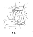
- Figure 1 is a side elevational view of a boot liner in accordance with one embodiment of the present invention
- FIG 2 is a rear elevational view of the boot liner illustrated in Figure 1 in accordance with the present invention.
- FIG 3 is a top plan view of the boot liner illustrated in Figures 1 and 2 in accordance with the present invention.
- a boot liner 1 is illustrated in accordance with a first embodiment of the present invention.
- This boot liner 1 is an inner boot liner that is disposed inside an outer boot 3 of a snowboard boot 5.
- the boot liner 1 basically comprises a sole 11, an upper part 13, a rear support 15, and a fastening mechanism 19.
- the outer boot 3 is the same as a conventional outer boot and thus will not be discussed or illustrated in detail herein.
- the sole 11 is the section forming the bottom section of the boot liner 1.
- the sole 11 has a generally foot shaped outline or peripheral edge.
- the peripheral edge of the sole 11 is sewn into or bonded to the lower end or edge of the upper part 13.
- the sole 11 is configured and arranged to have a specific cushioning effect.
- the sole 11 is configured to have an outer sole portion and an inner sole portion (neither is shown) in which the outer sole portion is sewn into the upper part 13 and the inner sole portion is layered and detachably disposed on top of the outer sole portion.
- the upper part 13 is a section formed into a shape to extend upwardly and over the sole 11 to form a foot receiving space to cover the foot and ankle of the wearer.
- the upper part 13 has a rear portion 21, a pair of side parts 23, a front part 25, and a tongue 27.
- the rear portion 21, the side parts 23, the front part 25, and the tongue 27 are all configured from materials and in shapes that allow adequate heat retention and an adequate perceived fit to be obtained.
- the rear portion 21 is a section forming the rear section of the upper part 13, and this part supports the rear section of the wearer's ankle.
- the side parts 23 are sections forming the side sections on both sides of the upper part 13.
- the side parts 23 are integrally formed with the rear portion 21 as a one-piece, unitary member.
- the side parts 23 support the side sections of the wearer's ankle.
- the front ends 24 of the side parts 23 are disposed to face each other at the front of the ankle, and form a slit 26 together with the front part 25.
- a rubber band 29 for pressing the tongue 27 against the ankle of the wearer is mounted extending in the width direction at the bottom section of the slit 26.
- the front part 25 is a section forming the front section of the upper part 13, and is integrally formed with the side parts 23 and the rear portion 21 as a one-piece, unitary member.
- the front part 25 is formed into a shape so as to cover the tip of the wearer's foot.
- the tongue 27 is a section provided to cover the slit 26.
- the tongue 27 is a separate element from the other sections 21, 23, and 25, and only the bottom end of the tongue 27 is sewn onto the section of the front part 25 forming the slit 26.
- the tongue 27 supports the front section of the wearer's ankle.
- the rear support 15 is a belt-shaped member extending vertically over the surface of the rear portion 21 in a direction perpendicular to the sole 11.
- the rear support 15 has a pair of restraint sections 16 and 17 formed by the rear support 15 being sewn into the rear portion 21, and a release section 18 that is not sewn onto the rear portion 21.
- the dotted lines on the rear support 15 and the straps 31, 37, and 38 indicate stitching where the rear support 15 and the straps 31, 37, and 38 are sewn to the upper part 13.
- the restraint section 16 is a section sewn from a vertically central part of the rear portion 21 to a top part of the rear portion 21, while the restraint section 17 is a section sewn into a bottom section of the rear portion 21.
- the restraint section 16 is overlapped on and sewn to a first fixed strap part 32 (described later) of a main strap 31 sewn into the rear portion 21.
- the restraint section 16 restrains the first fixed strap part 32 from moving in relation to the upper part 13.
- the release section 18 is formed at a position corresponding to the section adjacent to the top of the wearer's heel (or the rear section of the ankle).
- the release section 18 is disposed such that two movable strap parts 33 (described later) of the main strap 31 intersect each other between the release section 18 and the rear portion 21.
- the movable strap parts 33 3 are made immobile in relation to the rear portion 21.
- the area at which the two movable strap parts 33 intersect each other is constrained from moving vertically by the restraints 16 and 17.
- the fastening mechanism 19 is a mechanism for fastening the upper part 13 such that the upper part 13 fits to the ankle of the wearer, and the mechanism comprises the main strap 31 and two support straps 37 and 38.
- the main strap 31 is a belt-shaped member disposed at the vertically central section of the upper part 13.
- the main strap 31 includes the first fixed strap part 32, the two movable strap parts 33, and a pair of second fixed strap parts 34, all formed integrally with each other as a one-piece, unitary strap.
- the first fixed strap part 32 is a section extending horizontally between the horizontally central parts of the side parts 23 and around the rear portion 21.
- the first fixed strap part 32 is sewn into the upper part 13 so as to be stationary.
- the two length of the first fixed strap part 32 is sewn to the upper part 13. While only one side of the boot liner 1 is shown in Figure 1, it will be apparent from this disclosure that the opposite side of the boot liner 1 has the same configuration. In other words, if the opposite side of the boot liner 1 was illustrated, it would be a mirror image of Figure 1.
- the two movable strap parts 33 are two sections of the main strap 31, with each of the two movable strap parts 33 including a horizontal section extending from one end of the first fixed strap part 32 and a diagonal section extending diagonally downward from one side of the boot liner 1, around the rear end of the boot liner 1, to the second fixed strap part 34 at the opposite side of the boot liner 1. More specifically, the movable strap parts 33 are disposed to first extend forwardly in a horizontal direction from the forward ends of the first fixed strap part 32 along the surfaces of the side parts 23, then folding at a position slightly behind the front ends 24, and finally slanting rearwardly and downwardly to the sole 11.
- two movable strap parts 33 forms a pair of centrally located insertion element 33a at one end and a pair of distal ends 33b fixed to the sole 11 by the second fixed strap parts 34.
- the distal ends 33b extend along the surface of the rear portion 21 to the bottom sections of the side parts 23 on opposite sides.
- the movable strap parts 33 bend back behind the front ends 24 so that the insertion element 33a is formed through which the shoelace 20 or other such lace-shaped member can be inserted.
- the movable part 33 is not sewn into the upper part 13 and can move in relation to the upper part 13.
- the second fixed strap parts 34 are sections extending from the distal ends 33b of the movable strap parts 33 to the sole 11, with the free ends are fixed to the sole 11. Also, the second fixed strap parts 34 are each restrained and kept immobile in relation to the upper part 13 by being superposed and sewn into an area near the sole 11 by a sub-strap 38 disposed at the bottom of the main strap 31.
- the sub-straps 37 and 38 are belt-shaped sections similar to the main strap 31.
- the sub-strap 37 is disposed above the main strap 31 while the sub-strap 38 is disposed below the main strap 31.
- the sub-strap 37 is disposed extending from the rear portion 21 to the front along the surfaces of the side parts 23, folding at a position slightly behind the front ends 24, and slanting back to extend down to the rear portion 21.
- An insertion element 37a through which the shoelace 20 or the like can be inserted is formed in the folding area of the sub-strap 37. All of the sections of the sub-strap 37 are sewn into the upper part 13, except for the section in which the insertion element 37a is formed.
- the sub-strap 38 is disposed extending from both sides of the rear section of the sole 11 along the surfaces of the side parts 23 slanting forward to the top, and folding at a position slightly behind the front ends 24 to extend down to the longitudinally central section of the sole 11.
- An insertion element 38a through which the shoelace 20 or the like can be inserted is formed in the folding area of the sub-strap 38. Similar to the sub-strap 37, all of the sections of the sub-strap 38 are sewn into the upper part 13, except for the section in which the insertion element 38a is formed.
- the shoelace 20 is inserted in advance through the insertion elements 38a, 37a, and 33a in the order indicated.
- the foot is then inserted into the boot liner 1, and the shoelace 20 is pulled so that the front ends 24 of the upper part 13 move closer to each other.
- the sub-straps 37 and 38 in the top and bottom sections of the upper part 13 are pulled forward by using the insertion elements 37a and 38a, whereby the upper part 13 is deformed so that the opposing front ends 24 move closer to each other, and a sensation of a specific fit is created.
- the folding position of the main strap 31 in the vertically central section of the upper part 13 moves forward, and the insertion element 33a moves farther forward in comparison with its position before the fastening operation.
- the sections of the movable strap parts 33 extending back from the insertion element 33a to the rear are then pulled toward the insertion element 33a, and the rearward section of the upper part 13 is deformed.
- This deformation causes the upper part 13 to be firmly pressed against the area of the wearer's ankle, allowing the wearer to clearly feel a sensation of the upper part 13 fitting to the ankle.
- this boot liner 1 A particular feature of this boot liner 1 is that the rear section of the upper part 13 can be more firmly pressed against the ankle of the wearer because the movable strap parts 33 intersect at the back of the upper part 13, and thus a sensation of a comfortable fit is obtained.
- the boot liner can be used not only as an inner boot liner for snowboarding, but also in other footwear products having an outer boot (including an outer shell whose surface section is configured from hardened material), such as a ski boot or a hiking boot.
- an outer boot including an outer shell whose surface section is configured from hardened material
- the number of sub-straps, arrangement and position of parts, and the like can be modified as necessary.
- the following directional terms "forward, rearward, above, downward, vertical, horizontal, below and transverse” as well as any other similar directional terms refer to those directions of a boot liner in its normal use position. Accordingly, these terms, as utilized to describe the present invention should be interpreted relative to a boot liner in its normal use position. Moreover, the terms of degree such as “substantially”, “about” and “approximately” as used herein mean a reasonable amount of deviation of the modified term such that the end result is not significantly changed. These terms should be construed as including a deviation of at least ⁇ 5% of the modified term if this deviation would not negate the meaning of the word it modifies.
Landscapes
- Health & Medical Sciences (AREA)
- General Health & Medical Sciences (AREA)
- Physical Education & Sports Medicine (AREA)
- Footwear And Its Accessory, Manufacturing Method And Apparatuses (AREA)
- Cylinder Crankcases Of Internal Combustion Engines (AREA)
Abstract
Description
- The present invention generally relates to a boot liner. More specifically, the present invention relates to an inner boot liner for a snowboard boot.
- Ski boots, snowboard boots, and other such thermal footwear products generally comprise an outer boot disposed on the outside and a boot liner (inner boot) disposed on the inside of the outer boot. In most cases boot liners are configured in a shape and a material so as to provide warmth to the wearer's feet, shock absorption, good foot comfort, and the like.
- Boot liners generally comprise a sole forming the bottom portion of the boot and an upper part formed extending over the top of the sole so as to cover the foot and ankle of the wearer. The upper part has a rear portion for supporting the rear section of the ankle, and a pair of side parts that support the side sections of the ankle and are integrally formed with the rear portion. In the pair of side parts, the front ends are disposed separated from each other, and a slit is formed in the front section of the ankle. A tongue for supporting the front section of the ankle is fitted extending to the top in the bottom end of the slit (for example, see UK Patent No. 5924218).
- Examples of this type of conventional boot liner include those that further comprise a fastening mechanism for improving the perceived fit of the upper part on the foot. The fastening mechanism normally has a plurality of insertion elements disposed in the vicinity of the front end of the upper part at intervals in the vertical direction. Each insertion element is formed in a loop shape so that a shoelace or other such lace-shaped member can be inserted (for example, see UK Patent No. 5937542).
- In such a boot liner, for example, the ends of the shoelace are inserted in a pair of insertion elements at the same vertically aligned positions, the ends are intersected while being pulled so that the front ends move closer to each other, the operation of inserting them into adjacent insertion elements in the front end at opposite sides is repeated, and the ends are then tied together and fixed to each other, whereby the upper part is pressed against the wearer's foot, and a specific sensation of fitting is obtained.
- In the above-mentioned conventional boot liner, the deformation of the upper part is limited to a condition in which the front ends merely come closer to each other when fastened to the ankle of the wearer, for which reason the sensation of fitting on the ankle is sometimes insufficient.
- In view of the above, it will be apparent to those skilled in the art from this disclosure that there exists a need for an improved boot liner. This invention addresses this need in the art as well as other needs, which will become apparent to those skilled in the art from this disclosure.
- One object of the present invention is to provide a boot liner wherein the sensation of the upper part fitting on the ankle can be adequately obtained.
- In accordance with a first aspect of the present invention, a boot liner is provided that basically comprises a sole, an upper part, and a fastening mechanism. The upper part is coupled to the sole to extend over the sole to form a foot receiving space. The upper part includes a rear portion configured and arranged to support a rear area of a wearer's ankle, and a pair of side parts formed integrally with the rear portion to support side sections of the ankle. The side parts of the upper part both have front ends facing each other at the front of the ankle. The fastening mechanism is a mechanism that is coupled to the upper part and configured and arranged to tighten the upper part about the wearer's ankle.
- The fastening mechanism comprises a main strap member. This main strap member has a first fixed strap part, a pair of movable strap parts, and a second fixed strap part. The first fixed strap part are fixed to the rear portion of the upper part and extend generally in a horizontal direction. The pair of movable strap parts extend generally forward from forward ends of the first fixed strap part along side surfaces of the upper part. The pair of movable strap parts are folded back to form a pair of insertion elements in the vicinity of the front ends of the upper part wherein lace-shaped members can be inserted. The pair of movable strap parts are moveable in relation to the upper part such that the movable strap parts extend from the insertion elements along one of the side surfaces to an opposite side of the side surfaces with the movable strap parts intersecting each other at the rear portion. The pair of second fixed strap parts are fixed to at least one of the sole and the upper part. The second fixed strap parts also extends from distal ends of the movable strap parts.
- In the present invention, the words expressing directions such as top, bottom, front, rear, side, width, horizontal, and vertical indicate directions specified using the wearer's body as a standard when the wearer of the boot liner is standing in a natural posture.
- When the upper part of this boot liner is fastened to the ankle, a shoelace or other such lace-shaped member, for example, is inserted in a pair of insertion elements and are pulled such that the front ends move closer to each other. The folding location of the movable strap parts then moves, and the insertion elements move farther forward in comparison with their positions before the fastening operation. Then, the sections of the movable strap parts extending from the insertion elements to the rear are pulled toward the insertion elements, and the rearward section of the upper part is deformed.
- This deformation causes the upper part to be firmly pressed against the ankle of the wearer, and a stronger sensation of the upper part fitting to the ankle can be felt in comparison with a case in which the upper part is deformed such that the front ends merely move closer to each other.
- A particular feature of this boot liner is that the rear section of the upper part can be more firmly pressed against the ankle of the wearer because the movable strap parts intersect at the back of the upper part, and thus a sensation of a comfortable fit is obtained.
- In accordance with a second aspect of the present invention, the boot liner of the first aspect of the present invention is configured such that the movable strap parts intersect each other at the rear area of the wearer's ankle that is adjacent to a top of a heel. With this boot liner, the upper part is effectively fitted to the ankle of the wearer during fastening because the upper part is deformed such that the rear portion is pressed against the very top section of the heel of the wearer.
- In accordance with a third aspect of the present invention, the boot liner of the first and/or second aspects of the present invention is configured such that it further comprises a rear support. The rear support of the upper part includes a vertically extending rear support having a restraint section and a release section. The restraint is provided at the rear portion of the upper part. The restraint section is configured and arranged to restrain the first fixed strap part of the main strap member to prevent movement in relation to the rear portion of the upper part. The release section is configured and arranged to moveble retain of the movable strap parts of the main strap member in relation to the upper part. Thus, the rear support is designed for restraining the first fixed strap part of the main strap member to prevent movement in relation to the rear portion and to allow movement of the movable strap parts of the main strap member in relation to the upper part. With this boot liner, the effects of fastening the upper part with the movable strap parts can be adequately obtained because the movable strap parts can move freely without being constrained by the rear support.
- In accordance with a fourth aspect of the present invention, the boot liner in any one of the first through third aspects of the present invention is configured such that the first fixed strap part of the main strap member is fixed to and extends horizontally from the rear portion of the upper part to the horizontally central section of the side part. In this boot liner, the movable strap parts can move in relation to the upper part only in the front side section, rather than in the central section of the side part. Limiting the range of movement of the movable strap parts in this manner makes it possible for the upper part to be locally deformed in the rear section, and the perceived fit in the rear section of the ankle to be enhanced.
- In accordance with a fifth aspect of the present invention, the boot liner in any one of the first through fourth aspects of the present invention is configured such that the fastening mechanism further comprises an upper auxiliary strap member and a lower auxiliary strap member. The upper auxiliary strap member is coupled to the upper part to form a pair of upper insertion elements near the front ends of the upper part at locations above the insertion elements of the main strap member. The lower auxiliary strap member is coupled to the upper part to form a pair of lower insertion elements near the front ends of the upper part at locations below the insertion elements of the main strap member. In this boot liner, lace-shaped members can also be inserted through the insertion elements of the auxiliary strap members, thus allowing the upper part to be fastened in the vertical direction over a wide range, and the perceived fit on the ankle to be enhanced.
- In accordance with a sixth aspect of the present invention, the boot liner in any one of the fifth aspect of the present invention is configured such that the movable strap parts of the main strap member are restrained to be immobile in relation to the upper part in a vicinity of the sole by the lower auxiliary strap member positioned below the main strap member. In this boot liner, restraining the main strap member in the vicinity of the sole of the upper part by the auxiliary strap members makes it possible, for example, to overcome shortcomings whereby the movable strap parts are twisted or the inner walls of the outer boot are stretched when the boot liner is inserted into the outer boot.
- In accordance with a seventh aspect of the present invention, the boot liner of the fifth and/or sixth aspects of the present invention is configured such that the upper and lower auxiliary strap members are fixedly coupled to the upper part along their lengths, except for areas near the front ends of the upper part. In this boot liner, the auxiliary strap members do not have movable strap parts in the same way as the main strap member does, so the upper part can be fastened such that the front ends are merely moved closer to each other during fastening. Consequently, the fastening effect from the main strap member can be enhanced in relative fashion, and the wearer can clearly feel the fastening effect in the base section of the ankle.
- In accordance with an eighth aspect of the present invention, the boot liner in any one of the first through seventh aspects of the present invention is configured such that the insertion elements are formed behind the front ends. In this boot liner, the extreme back sections of the front ends can be stretched when the upper part is fastened, making it possible to bring the front ends closer to each other in an efficient manner.
- In accordance with a ninth aspect of the present invention, the boot liner in any one of the first through eighth aspects of the present invention is configured such that the sole and the upper part are configured and arranged to form an inner boot liner of a snowboard boot having an outer boot. In this boot liner, the wearer can have the sensation of a comfortable fit, particularly when the boot liner is used as an inner boot liner for a snowboard boot.
- According to the present invention, the upper part is strongly pressed against the ankle of the wearer by a main strap member that has movable strap parts, and the sensation of the upper part fitting to the ankle can be felt more clearly compared with cases in which the upper part is merely deformed to move the front ends closer to each other.
- These and other objects, features, aspects and advantages of the present invention will become apparent to those skilled in the art from the following detailed description, which, taken in conjunction with the annexed drawings, discloses a preferred embodiment of the present invention.
- Referring now to the attached drawings which form a part of this original disclosure:
- Figure 1 is a side elevational view of a boot liner in accordance with one embodiment of the present invention;
- Figure 2 is a rear elevational view of the boot liner illustrated in Figure 1 in accordance with the present invention; and
- Figure 3 is a top plan view of the boot liner illustrated in Figures 1 and 2 in accordance with the present invention.
- Selected embodiments of the present invention will now be explained with reference to the drawings. It will be apparent to those skilled in the art from this disclosure that the following descriptions of the embodiments of the present invention are provided for illustration only and not for the purpose of limiting the invention as defined by the appended claims and their equivalents.
- Referring to Figures 1-3, a
boot liner 1 is illustrated in accordance with a first embodiment of the present invention. Thisboot liner 1 is an inner boot liner that is disposed inside anouter boot 3 of asnowboard boot 5. Theboot liner 1 basically comprises a sole 11, anupper part 13, arear support 15, and afastening mechanism 19. Theouter boot 3 is the same as a conventional outer boot and thus will not be discussed or illustrated in detail herein. - The sole 11 is the section forming the bottom section of the
boot liner 1. Thus, the sole 11 has a generally foot shaped outline or peripheral edge. The peripheral edge of the sole 11 is sewn into or bonded to the lower end or edge of theupper part 13. The sole 11 is configured and arranged to have a specific cushioning effect. Preferably, the sole 11 is configured to have an outer sole portion and an inner sole portion (neither is shown) in which the outer sole portion is sewn into theupper part 13 and the inner sole portion is layered and detachably disposed on top of the outer sole portion. - The
upper part 13 is a section formed into a shape to extend upwardly and over the sole 11 to form a foot receiving space to cover the foot and ankle of the wearer. Theupper part 13 has arear portion 21, a pair ofside parts 23, afront part 25, and atongue 27. Therear portion 21, theside parts 23, thefront part 25, and thetongue 27 are all configured from materials and in shapes that allow adequate heat retention and an adequate perceived fit to be obtained. - The
rear portion 21 is a section forming the rear section of theupper part 13, and this part supports the rear section of the wearer's ankle. - The
side parts 23 are sections forming the side sections on both sides of theupper part 13. Theside parts 23 are integrally formed with therear portion 21 as a one-piece, unitary member. Theside parts 23 support the side sections of the wearer's ankle. Also, the front ends 24 of theside parts 23 are disposed to face each other at the front of the ankle, and form aslit 26 together with thefront part 25. Arubber band 29 for pressing thetongue 27 against the ankle of the wearer is mounted extending in the width direction at the bottom section of theslit 26. - The
front part 25 is a section forming the front section of theupper part 13, and is integrally formed with theside parts 23 and therear portion 21 as a one-piece, unitary member. Thefront part 25 is formed into a shape so as to cover the tip of the wearer's foot. - The
tongue 27 is a section provided to cover theslit 26. Thetongue 27 is a separate element from theother sections tongue 27 is sewn onto the section of thefront part 25 forming theslit 26. Thetongue 27 supports the front section of the wearer's ankle. - As shown in Figure 2, the
rear support 15 is a belt-shaped member extending vertically over the surface of therear portion 21 in a direction perpendicular to the sole 11. Therear support 15 has a pair ofrestraint sections rear support 15 being sewn into therear portion 21, and arelease section 18 that is not sewn onto therear portion 21. In Figures 1 and 2, the dotted lines on therear support 15 and thestraps rear support 15 and thestraps upper part 13. - The
restraint section 16 is a section sewn from a vertically central part of therear portion 21 to a top part of therear portion 21, while therestraint section 17 is a section sewn into a bottom section of therear portion 21. Here therestraint section 16 is overlapped on and sewn to a first fixed strap part 32 (described later) of amain strap 31 sewn into therear portion 21. Thus, therestraint section 16 restrains the first fixedstrap part 32 from moving in relation to theupper part 13. - The
release section 18 is formed at a position corresponding to the section adjacent to the top of the wearer's heel (or the rear section of the ankle). Therelease section 18 is disposed such that two movable strap parts 33 (described later) of themain strap 31 intersect each other between therelease section 18 and therear portion 21. Themovable strap parts 33 3 are made immobile in relation to therear portion 21. The area at which the twomovable strap parts 33 intersect each other is constrained from moving vertically by therestraints - The
fastening mechanism 19 is a mechanism for fastening theupper part 13 such that theupper part 13 fits to the ankle of the wearer, and the mechanism comprises themain strap 31 and twosupport straps - The
main strap 31 is a belt-shaped member disposed at the vertically central section of theupper part 13. Themain strap 31 includes the first fixedstrap part 32, the twomovable strap parts 33, and a pair of second fixedstrap parts 34, all formed integrally with each other as a one-piece, unitary strap. - The first fixed
strap part 32 is a section extending horizontally between the horizontally central parts of theside parts 23 and around therear portion 21. The first fixedstrap part 32 is sewn into theupper part 13 so as to be stationary. Preferably, the two length of the first fixedstrap part 32 is sewn to theupper part 13. While only one side of theboot liner 1 is shown in Figure 1, it will be apparent from this disclosure that the opposite side of theboot liner 1 has the same configuration. In other words, if the opposite side of theboot liner 1 was illustrated, it would be a mirror image of Figure 1. - The two
movable strap parts 33 are two sections of themain strap 31, with each of the twomovable strap parts 33 including a horizontal section extending from one end of the first fixedstrap part 32 and a diagonal section extending diagonally downward from one side of theboot liner 1, around the rear end of theboot liner 1, to the second fixedstrap part 34 at the opposite side of theboot liner 1. More specifically, themovable strap parts 33 are disposed to first extend forwardly in a horizontal direction from the forward ends of the first fixedstrap part 32 along the surfaces of theside parts 23, then folding at a position slightly behind the front ends 24, and finally slanting rearwardly and downwardly to the sole 11. - Thus, two
movable strap parts 33 forms a pair of centrally locatedinsertion element 33a at one end and a pair ofdistal ends 33b fixed to the sole 11 by the second fixedstrap parts 34. The distal ends 33b extend along the surface of therear portion 21 to the bottom sections of theside parts 23 on opposite sides. Themovable strap parts 33 bend back behind the front ends 24 so that theinsertion element 33a is formed through which theshoelace 20 or other such lace-shaped member can be inserted. Themovable part 33 is not sewn into theupper part 13 and can move in relation to theupper part 13. - The second fixed
strap parts 34 are sections extending from the distal ends 33b of themovable strap parts 33 to the sole 11, with the free ends are fixed to the sole 11. Also, the second fixedstrap parts 34 are each restrained and kept immobile in relation to theupper part 13 by being superposed and sewn into an area near the sole 11 by a sub-strap 38 disposed at the bottom of themain strap 31. - The sub-straps 37 and 38 are belt-shaped sections similar to the
main strap 31. The sub-strap 37 is disposed above themain strap 31 while the sub-strap 38 is disposed below themain strap 31. - The sub-strap 37 is disposed extending from the
rear portion 21 to the front along the surfaces of theside parts 23, folding at a position slightly behind the front ends 24, and slanting back to extend down to therear portion 21. Aninsertion element 37a through which theshoelace 20 or the like can be inserted is formed in the folding area of the sub-strap 37. All of the sections of the sub-strap 37 are sewn into theupper part 13, except for the section in which theinsertion element 37a is formed. - The sub-strap 38 is disposed extending from both sides of the rear section of the sole 11 along the surfaces of the
side parts 23 slanting forward to the top, and folding at a position slightly behind the front ends 24 to extend down to the longitudinally central section of the sole 11. Aninsertion element 38a through which theshoelace 20 or the like can be inserted is formed in the folding area of the sub-strap 38. Similar to the sub-strap 37, all of the sections of the sub-strap 38 are sewn into theupper part 13, except for the section in which theinsertion element 38a is formed. - When the
boot liner 1 thus configured is to be fitted to the foot of the wearer, as shown in Figure 1, theshoelace 20 is inserted in advance through theinsertion elements boot liner 1, and theshoelace 20 is pulled so that the front ends 24 of theupper part 13 move closer to each other. Then the sub-straps 37 and 38 in the top and bottom sections of theupper part 13 are pulled forward by using theinsertion elements upper part 13 is deformed so that the opposing front ends 24 move closer to each other, and a sensation of a specific fit is created. - Conversely, the folding position of the
main strap 31 in the vertically central section of theupper part 13 moves forward, and theinsertion element 33a moves farther forward in comparison with its position before the fastening operation. The sections of themovable strap parts 33 extending back from theinsertion element 33a to the rear are then pulled toward theinsertion element 33a, and the rearward section of theupper part 13 is deformed. This deformation causes theupper part 13 to be firmly pressed against the area of the wearer's ankle, allowing the wearer to clearly feel a sensation of theupper part 13 fitting to the ankle. - A particular feature of this
boot liner 1 is that the rear section of theupper part 13 can be more firmly pressed against the ankle of the wearer because themovable strap parts 33 intersect at the back of theupper part 13, and thus a sensation of a comfortable fit is obtained. - The boot liner can be used not only as an inner boot liner for snowboarding, but also in other footwear products having an outer boot (including an outer shell whose surface section is configured from hardened material), such as a ski boot or a hiking boot. The number of sub-straps, arrangement and position of parts, and the like can be modified as necessary.
- As used herein, the following directional terms "forward, rearward, above, downward, vertical, horizontal, below and transverse" as well as any other similar directional terms refer to those directions of a boot liner in its normal use position. Accordingly, these terms, as utilized to describe the present invention should be interpreted relative to a boot liner in its normal use position. Moreover, the terms of degree such as "substantially", "about" and "approximately" as used herein mean a reasonable amount of deviation of the modified term such that the end result is not significantly changed. These terms should be construed as including a deviation of at least ± 5% of the modified term if this deviation would not negate the meaning of the word it modifies.
- This application claims priority to Japanese Patent Application No. 2003-031328. The entire disclosure of Japanese Patent Application No. 2003-031328 is hereby incorporated herein by reference.
- While only selected embodiments have been chosen to illustrate the present invention, it will be apparent to those skilled in the art from this disclosure that various changes and modifications can be made herein without departing from the scope of the invention as defined in the appended claims. Furthermore, the foregoing descriptions of the embodiments according to the present invention are provided for illustration only, and not for the purpose of limiting the invention as defined by the appended claims and their equivalents.
Claims (9)
- A boot liner comprising:a sole (11);an upper part (13) coupled to the sole to extend over the sole to form a foot receiving space, the upper part including a rear portion (21) configured and arranged to support a rear area of a wearer's ankle, and a pair of side parts (23) formed integrally with the rear portion (21) to support side sections of the ankle, the side parts of the upper part both having front ends (24) facing each other at the front of the ankle; anda fastening mechanism (19) coupled to the upper part (13) and configured and arranged to tighten the upper part about the wearer's ankle, and the fastening mechanism having a main strap member (31 ) comprisinga first fixed strap part (32) fixed to the rear portion of the upper part and extending generally in a horizontal direction,a pair of movable strap parts (33) extending generally forward from forward ends of the first fixed strap part along side surfaces of the upper part, the movable strap parts being folded back to form a pair of insertion elements (33a) in the vicinity of the front ends of the upper part, and the movable strap parts being moveable in relation to the upper part such that the movable strap parts extend from the insertion elements along one of the side surfaces to an opposite side of the side surfaces with the movable strap parts intersecting each other at the rear portion, anda pair of second fixed strap parts (34) fixed to at least one of the sole and the upper part, the second fixed strap parts extending from distal ends of the movable strap parts.
- The boot liner according to claim 1, wherein
the movable strap parts (33) are configured and arranged to intersect each other at the rear area of the wearer's ankle that is adjacent to a top of a heel. - The boot liner according to claim 1 or 2, wherein
the rear portion (21) of the upper part (13) includes a vertically extending rear support (15) having a restraint section (16, 17) and a release section (18), the restraint section being configured and arranged to restrain the first fixed strap part (32) of the main strap member (31) to prevent movement in relation to the rear portion of the upper part, and the release section (18) being configured and arranged to moveably retain the movable strap parts (33) of the main strap member in relation to the upper part. - The boot liner according to any one of claims 1 to 3, wherein
the first fixed strap part (32) of the main strap member is fixed to and extends horizontally from the rear portion of the upper part to horizontally central sections of the side parts. - The boot liner according to any one of claims 1 to 4, wherein
the fastening mechanism (19) further comprises an upper auxiliary strap member (37) coupled to the upper part to form a pair of upper insertion elements (37a) near the front ends of the upper part at locations above the insertion elements (33a) of the main strap member; and
the fastening mechanism further comprises a lower auxiliary strap member (38) coupled to the upper part to form a pair of lower insertion elements (38a) near the front ends of the upper part at locations below the insertion elements (33a) of the main strap member. - The boot liner according to claim 5, wherein
the movable strap parts of the main strap member are restrained to be immobile in relation to the upper part in a vicinity of the sole by the lower auxiliary strap member (38) positioned below the main strap member. - The boot liner according to claim 5 or 6, wherein the upper and lower auxiliary strap members (38, 37) are fixedly coupled to the upper part along their lengths, except for areas near the front ends of the upper part.
- The boot liner according to any of claims 1 to 7, wherein
the insertion elements are formed behind the front ends. - The boot liner according to any one of claims 1 to 8, wherein
the sole and the upper part are configured and arranged to form an inner boot liner of a snowboard boot having an outer boot.
Applications Claiming Priority (2)
| Application Number | Priority Date | Filing Date | Title |
|---|---|---|---|
| JP2003031328A JP3746043B2 (en) | 2003-02-07 | 2003-02-07 | Boot liner |
| JP2003031328 | 2003-02-07 |
Publications (2)
| Publication Number | Publication Date |
|---|---|
| EP1444909A1 true EP1444909A1 (en) | 2004-08-11 |
| EP1444909B1 EP1444909B1 (en) | 2006-03-29 |
Family
ID=32653021
Family Applications (1)
| Application Number | Title | Priority Date | Filing Date |
|---|---|---|---|
| EP04001804A Expired - Lifetime EP1444909B1 (en) | 2003-02-07 | 2004-01-28 | Boots liner |
Country Status (7)
| Country | Link |
|---|---|
| US (1) | US6952891B2 (en) |
| EP (1) | EP1444909B1 (en) |
| JP (1) | JP3746043B2 (en) |
| CN (1) | CN1244302C (en) |
| AT (1) | ATE321467T1 (en) |
| DE (1) | DE602004000542T2 (en) |
| TW (1) | TWI233367B (en) |
Cited By (4)
| Publication number | Priority date | Publication date | Assignee | Title |
|---|---|---|---|---|
| AT501443A1 (en) * | 2005-02-04 | 2006-09-15 | Atomic Austria Gmbh | SPORTS SHOE FOR RUNNING OR SHIELDING |
| DE102006034955A1 (en) * | 2006-07-28 | 2008-01-31 | Head Germany Gmbh | snowboard boots |
| EP2446761A3 (en) * | 2009-04-16 | 2012-07-04 | Nike International Ltd. | Article of footwear for snowboarding |
| WO2016191752A1 (en) * | 2015-05-28 | 2016-12-01 | Brooks Sports, Inc. | Shoe constructions having upper assemblies with independently movable booties and decoupled sole assemblies |
Families Citing this family (42)
| Publication number | Priority date | Publication date | Assignee | Title |
|---|---|---|---|---|
| US7293371B2 (en) * | 2004-09-22 | 2007-11-13 | Nike, Inc. | Woven shoe with integral lace loops |
| US7131219B2 (en) * | 2004-10-15 | 2006-11-07 | Eddie Chen | Shoe with leg support |
| KR100833682B1 (en) * | 2006-04-27 | 2008-05-29 | 황종오 | Tying tool for shoelace |
| US7574818B2 (en) * | 2006-05-25 | 2009-08-18 | Nike, Inc. | Article of footwear having an upper with thread structural elements |
| JP5709526B2 (en) | 2008-01-18 | 2015-04-30 | ボア テクノロジー,インコーポレイテッド | Occlusion system |
| US8056269B2 (en) | 2008-05-02 | 2011-11-15 | Nike, Inc. | Article of footwear with lighting system |
| US11723436B2 (en) | 2008-05-02 | 2023-08-15 | Nike, Inc. | Article of footwear and charging system |
| US9907359B2 (en) | 2008-05-02 | 2018-03-06 | Nike, Inc. | Lacing system with guide elements |
| US8046937B2 (en) | 2008-05-02 | 2011-11-01 | Nike, Inc. | Automatic lacing system |
| US11206891B2 (en) | 2008-05-02 | 2021-12-28 | Nike, Inc. | Article of footwear and a method of assembly of the article of footwear |
| US10477911B2 (en) | 2008-05-02 | 2019-11-19 | Nike, Inc. | Article of footwear and charging system |
| US8302329B2 (en) | 2009-11-18 | 2012-11-06 | Nike, Inc. | Footwear with counter-supplementing strap |
| USD641147S1 (en) | 2009-12-14 | 2011-07-12 | Deckers Outdoor Corporation | Shoe upper |
| DE112011100318B4 (en) * | 2010-01-21 | 2023-04-20 | Boa Technology, Inc. | Guides for lacing systems |
| US20110308108A1 (en) * | 2010-06-21 | 2011-12-22 | Under Armour, Inc. | Foot support article |
| US9402437B2 (en) | 2010-06-21 | 2016-08-02 | Under Armour, Inc. | Foot support article |
| US9707119B2 (en) | 2010-06-21 | 2017-07-18 | Under Armour, Inc. | Foot support article |
| US8578632B2 (en) | 2010-07-19 | 2013-11-12 | Nike, Inc. | Decoupled foot stabilizer system |
| US8857077B2 (en) * | 2010-09-30 | 2014-10-14 | Nike, Inc. | Footwear with internal harness |
| US8756833B2 (en) | 2011-01-06 | 2014-06-24 | Nike, Inc. | Lacing closure system for an object |
| US11026473B2 (en) * | 2011-05-19 | 2021-06-08 | Under Armour, Inc. | Foot support article |
| EP3165112B1 (en) * | 2011-09-15 | 2023-11-08 | NB NewBoots SA | Sports boot |
| US9179739B2 (en) | 2012-06-21 | 2015-11-10 | Nike, Inc. | Footwear incorporating looped tensile strand elements |
| CN103340491B (en) * | 2013-07-29 | 2015-07-01 | 福建鸿星尔克体育用品有限公司 | Multifunctional shoes |
| USD701378S1 (en) * | 2013-10-18 | 2014-03-25 | Sorel Corporation | Footwear |
| USD701377S1 (en) * | 2013-10-18 | 2014-03-25 | Sorel Corporation | Footwear |
| USD740534S1 (en) * | 2015-01-22 | 2015-10-13 | Sorel Corporation | Footwear |
| USD740535S1 (en) * | 2015-01-29 | 2015-10-13 | Columbia Sportswear North America, Inc. | Footwear |
| CN104705899A (en) * | 2015-03-12 | 2015-06-17 | 东华大学 | Trekking shoe capable of being transformed to be climbing shoe |
| US9943126B2 (en) | 2015-03-13 | 2018-04-17 | Nike, Inc. | Waistband for article of apparel featuring cord and embroidery tunnel |
| US9848674B2 (en) | 2015-04-14 | 2017-12-26 | Nike, Inc. | Article of footwear with weight-activated cinching apparatus |
| USD849386S1 (en) * | 2015-09-08 | 2019-05-28 | Fuerst Group, Inc. | Footwear article |
| TWI607714B (en) * | 2016-07-21 | 2017-12-11 | Gary David Chang | Shoes with elastic uppers |
| US10588381B2 (en) | 2016-11-21 | 2020-03-17 | Under Armour, Inc. | Footwear with internal harness |
| USD982287S1 (en) * | 2019-10-08 | 2023-04-04 | Sorel Corporation | Article of footwear |
| USD957804S1 (en) | 2019-10-18 | 2022-07-19 | Fuerst Group, Inc. | Footwear article |
| USD931592S1 (en) * | 2019-10-18 | 2021-09-28 | Fuerst Group, Inc. | Footwear article |
| US12495864B2 (en) | 2023-03-22 | 2025-12-16 | Kaitlin Sadler | Snap-on clog-style shoe liner and method of use |
| USD1041818S1 (en) * | 2023-05-03 | 2024-09-17 | Inuikii Ag | Shoe |
| USD1041817S1 (en) * | 2023-05-03 | 2024-09-17 | Inuikii Ag | Shoe |
| USD1041815S1 (en) * | 2023-05-03 | 2024-09-17 | Inuikii Ag | Shoe |
| USD1041814S1 (en) * | 2023-05-03 | 2024-09-17 | Inuikii Ag | Shoe |
Citations (5)
| Publication number | Priority date | Publication date | Assignee | Title |
|---|---|---|---|---|
| US5992057A (en) * | 1998-01-29 | 1999-11-30 | Reebok International Ltd. | Strapping and closure system for an article of footwear |
| US6128835A (en) * | 1999-01-28 | 2000-10-10 | Mark Thatcher | Self adjusting frame for footwear |
| US6467193B1 (en) * | 2001-08-03 | 2002-10-22 | Shimano Inc. | Boot liner |
| EP1308104A2 (en) * | 2001-11-01 | 2003-05-07 | Lange International S.A. | Lacing system for inner-boot |
| FR2834182A1 (en) * | 2001-12-28 | 2003-07-04 | Salomon Sa | Pre-cast concrete playground system assembled on-site with pre-cast concrete pins |
Family Cites Families (8)
| Publication number | Priority date | Publication date | Assignee | Title |
|---|---|---|---|---|
| NZ282547A (en) * | 1994-02-28 | 1998-02-26 | Adam H Oreck | Shoe with tubes on the tongue and redirection devices on the perimeter of the sole for guiding laces in a criss cross fashion |
| FR2726743B1 (en) | 1994-11-10 | 1997-01-03 | Salomon Sa | COMFORT SHOE FOR SKI SHOE |
| FR2742969B1 (en) | 1995-12-27 | 1998-04-24 | Salomon Sa | INTERNAL SLIPPERS FOR SPORTS SHOES |
| USD385992S (en) * | 1996-06-04 | 1997-11-11 | Rocky Shoes and Boots, Inc. | Shoe upper |
| US6286233B1 (en) * | 1999-04-08 | 2001-09-11 | David E Gaither | Internally laced shoe |
| FR2805753B1 (en) | 2000-03-06 | 2002-05-17 | Salomon Sa | CABLE SOLE ASSEMBLY |
| FR2810510B1 (en) | 2000-06-27 | 2002-10-11 | Salomon Sa | COMFORT UPPER FOR FOOTWEAR |
| FR2814918B1 (en) | 2000-10-10 | 2003-03-14 | Salomon Sa | INTERNAL TIGHTENING DEVICE FOR FOOTWEAR |
-
2003
- 2003-02-07 JP JP2003031328A patent/JP3746043B2/en not_active Expired - Fee Related
-
2004
- 2004-01-16 US US10/758,591 patent/US6952891B2/en not_active Expired - Fee Related
- 2004-01-28 EP EP04001804A patent/EP1444909B1/en not_active Expired - Lifetime
- 2004-01-28 DE DE602004000542T patent/DE602004000542T2/en not_active Expired - Fee Related
- 2004-01-28 AT AT04001804T patent/ATE321467T1/en not_active IP Right Cessation
- 2004-02-05 CN CN200410003669.2A patent/CN1244302C/en not_active Expired - Fee Related
- 2004-02-06 TW TW093102805A patent/TWI233367B/en not_active IP Right Cessation
Patent Citations (5)
| Publication number | Priority date | Publication date | Assignee | Title |
|---|---|---|---|---|
| US5992057A (en) * | 1998-01-29 | 1999-11-30 | Reebok International Ltd. | Strapping and closure system for an article of footwear |
| US6128835A (en) * | 1999-01-28 | 2000-10-10 | Mark Thatcher | Self adjusting frame for footwear |
| US6467193B1 (en) * | 2001-08-03 | 2002-10-22 | Shimano Inc. | Boot liner |
| EP1308104A2 (en) * | 2001-11-01 | 2003-05-07 | Lange International S.A. | Lacing system for inner-boot |
| FR2834182A1 (en) * | 2001-12-28 | 2003-07-04 | Salomon Sa | Pre-cast concrete playground system assembled on-site with pre-cast concrete pins |
Cited By (12)
| Publication number | Priority date | Publication date | Assignee | Title |
|---|---|---|---|---|
| AT501443A1 (en) * | 2005-02-04 | 2006-09-15 | Atomic Austria Gmbh | SPORTS SHOE FOR RUNNING OR SHIELDING |
| AT501443B1 (en) * | 2005-02-04 | 2007-03-15 | Atomic Austria Gmbh | SPORTS SHOE FOR RUNNING OR SHIELDING |
| DE102006034955A1 (en) * | 2006-07-28 | 2008-01-31 | Head Germany Gmbh | snowboard boots |
| US7963049B2 (en) | 2006-07-28 | 2011-06-21 | Head Germany Gmbh | Snowboard boot |
| EP2446761A3 (en) * | 2009-04-16 | 2012-07-04 | Nike International Ltd. | Article of footwear for snowboarding |
| EP2540180A1 (en) * | 2009-04-16 | 2013-01-02 | Nike International Ltd. | Article of footwear for snowboarding |
| EP2556762A1 (en) * | 2009-04-16 | 2013-02-13 | Nike International Ltd. | Article of footwear for snowboarding |
| US8667711B2 (en) | 2009-04-16 | 2014-03-11 | Nike, Inc. | Article of footwear for snowboarding |
| US9420846B2 (en) | 2009-04-16 | 2016-08-23 | Nike, Inc. | Article of footwear for snowboarding |
| WO2016191752A1 (en) * | 2015-05-28 | 2016-12-01 | Brooks Sports, Inc. | Shoe constructions having upper assemblies with independently movable booties and decoupled sole assemblies |
| US9968161B2 (en) | 2015-05-28 | 2018-05-15 | Brooks Sports, Inc. | Shoe constructions having upper assemblies with independently movable booties and decoupled sole assemblies |
| US10555582B2 (en) | 2015-05-28 | 2020-02-11 | Brooks Sports, Inc. | Shoe constructions having upper assemblies with independently movable booties and decoupled sole assemblies |
Also Published As
| Publication number | Publication date |
|---|---|
| JP3746043B2 (en) | 2006-02-15 |
| DE602004000542T2 (en) | 2007-01-25 |
| TW200425932A (en) | 2004-12-01 |
| ATE321467T1 (en) | 2006-04-15 |
| TWI233367B (en) | 2005-06-01 |
| DE602004000542D1 (en) | 2006-05-18 |
| CN1518915A (en) | 2004-08-11 |
| US20040172848A1 (en) | 2004-09-09 |
| US6952891B2 (en) | 2005-10-11 |
| JP2004236971A (en) | 2004-08-26 |
| CN1244302C (en) | 2006-03-08 |
| EP1444909B1 (en) | 2006-03-29 |
Similar Documents
| Publication | Publication Date | Title |
|---|---|---|
| EP1444909B1 (en) | Boots liner | |
| AU2023200430B2 (en) | Rapid-Entry Footwear with Rebounding Fit System | |
| US6367171B1 (en) | Shoe | |
| EP2023756B1 (en) | Article of footwear with open upper | |
| JP7203126B2 (en) | shoes with counter | |
| JP5396570B2 (en) | Articulating footwear for sports activities | |
| US20110138656A1 (en) | Footwear with improved upper | |
| US6209229B1 (en) | Snowboard boot including an internal shell and a journalled rigid back portion | |
| US5430958A (en) | Athletic shoe | |
| US20040231196A1 (en) | Baby shoe | |
| JP2026082696A (en) | Shoes equipped with heel guard members | |
| CA3021511C (en) | Rapid-entry footwear with rebounding fit system | |
| CN118139554A (en) | Ankle protection shoe and ankle protection piece | |
| HK1262997B (en) | Rapid-entry footwear with rebounding fit system | |
| HK1262997A1 (en) | Rapid-entry footwear with rebounding fit system |
Legal Events
| Date | Code | Title | Description |
|---|---|---|---|
| PUAI | Public reference made under article 153(3) epc to a published international application that has entered the european phase |
Free format text: ORIGINAL CODE: 0009012 |
|
| AK | Designated contracting states |
Kind code of ref document: A1 Designated state(s): AT BE BG CH CY CZ DE DK EE ES FI FR GB GR HU IE IT LI LU MC NL PT RO SE SI SK TR |
|
| AX | Request for extension of the european patent |
Extension state: AL LT LV MK |
|
| 17P | Request for examination filed |
Effective date: 20040715 |
|
| AKX | Designation fees paid |
Designated state(s): AT BE BG CH CY CZ DE DK EE ES FI FR GB GR HU IE IT LI LU MC NL PT RO SE SI SK TR |
|
| GRAP | Despatch of communication of intention to grant a patent |
Free format text: ORIGINAL CODE: EPIDOSNIGR1 |
|
| GRAS | Grant fee paid |
Free format text: ORIGINAL CODE: EPIDOSNIGR3 |
|
| GRAA | (expected) grant |
Free format text: ORIGINAL CODE: 0009210 |
|
| AK | Designated contracting states |
Kind code of ref document: B1 Designated state(s): AT BE BG CH CY CZ DE DK EE ES FI FR GB GR HU IE IT LI LU MC NL PT RO SE SI SK TR |
|
| PG25 | Lapsed in a contracting state [announced via postgrant information from national office to epo] |
Ref country code: AT Free format text: LAPSE BECAUSE OF FAILURE TO SUBMIT A TRANSLATION OF THE DESCRIPTION OR TO PAY THE FEE WITHIN THE PRESCRIBED TIME-LIMIT Effective date: 20060329 Ref country code: BE Free format text: LAPSE BECAUSE OF FAILURE TO SUBMIT A TRANSLATION OF THE DESCRIPTION OR TO PAY THE FEE WITHIN THE PRESCRIBED TIME-LIMIT Effective date: 20060329 Ref country code: CH Free format text: LAPSE BECAUSE OF FAILURE TO SUBMIT A TRANSLATION OF THE DESCRIPTION OR TO PAY THE FEE WITHIN THE PRESCRIBED TIME-LIMIT Effective date: 20060329 Ref country code: LI Free format text: LAPSE BECAUSE OF FAILURE TO SUBMIT A TRANSLATION OF THE DESCRIPTION OR TO PAY THE FEE WITHIN THE PRESCRIBED TIME-LIMIT Effective date: 20060329 Ref country code: RO Free format text: LAPSE BECAUSE OF FAILURE TO SUBMIT A TRANSLATION OF THE DESCRIPTION OR TO PAY THE FEE WITHIN THE PRESCRIBED TIME-LIMIT Effective date: 20060329 Ref country code: SI Free format text: LAPSE BECAUSE OF FAILURE TO SUBMIT A TRANSLATION OF THE DESCRIPTION OR TO PAY THE FEE WITHIN THE PRESCRIBED TIME-LIMIT Effective date: 20060329 Ref country code: SK Free format text: LAPSE BECAUSE OF FAILURE TO SUBMIT A TRANSLATION OF THE DESCRIPTION OR TO PAY THE FEE WITHIN THE PRESCRIBED TIME-LIMIT Effective date: 20060329 |
|
| REG | Reference to a national code |
Ref country code: GB Ref legal event code: FG4D |
|
| REG | Reference to a national code |
Ref country code: CH Ref legal event code: EP |
|
| REG | Reference to a national code |
Ref country code: IE Ref legal event code: FG4D |
|
| REF | Corresponds to: |
Ref document number: 602004000542 Country of ref document: DE Date of ref document: 20060518 Kind code of ref document: P |
|
| PG25 | Lapsed in a contracting state [announced via postgrant information from national office to epo] |
Ref country code: BG Free format text: LAPSE BECAUSE OF FAILURE TO SUBMIT A TRANSLATION OF THE DESCRIPTION OR TO PAY THE FEE WITHIN THE PRESCRIBED TIME-LIMIT Effective date: 20060629 Ref country code: DK Free format text: LAPSE BECAUSE OF FAILURE TO SUBMIT A TRANSLATION OF THE DESCRIPTION OR TO PAY THE FEE WITHIN THE PRESCRIBED TIME-LIMIT Effective date: 20060629 Ref country code: SE Free format text: LAPSE BECAUSE OF FAILURE TO SUBMIT A TRANSLATION OF THE DESCRIPTION OR TO PAY THE FEE WITHIN THE PRESCRIBED TIME-LIMIT Effective date: 20060629 |
|
| PG25 | Lapsed in a contracting state [announced via postgrant information from national office to epo] |
Ref country code: ES Free format text: LAPSE BECAUSE OF FAILURE TO SUBMIT A TRANSLATION OF THE DESCRIPTION OR TO PAY THE FEE WITHIN THE PRESCRIBED TIME-LIMIT Effective date: 20060710 |
|
| RAP2 | Party data changed (patent owner data changed or rights of a patent transferred) |
Owner name: SHIMANO INC. |
|
| PG25 | Lapsed in a contracting state [announced via postgrant information from national office to epo] |
Ref country code: PT Free format text: LAPSE BECAUSE OF FAILURE TO SUBMIT A TRANSLATION OF THE DESCRIPTION OR TO PAY THE FEE WITHIN THE PRESCRIBED TIME-LIMIT Effective date: 20060829 |
|
| REG | Reference to a national code |
Ref country code: CH Ref legal event code: PL |
|
| NLT2 | Nl: modifications (of names), taken from the european patent patent bulletin |
Owner name: SHIMANO INC. Effective date: 20060802 |
|
| ET | Fr: translation filed | ||
| PGFP | Annual fee paid to national office [announced via postgrant information from national office to epo] |
Ref country code: CZ Payment date: 20070118 Year of fee payment: 4 |
|
| PG25 | Lapsed in a contracting state [announced via postgrant information from national office to epo] |
Ref country code: MC Free format text: LAPSE BECAUSE OF NON-PAYMENT OF DUE FEES Effective date: 20070131 |
|
| PLBE | No opposition filed within time limit |
Free format text: ORIGINAL CODE: 0009261 |
|
| STAA | Information on the status of an ep patent application or granted ep patent |
Free format text: STATUS: NO OPPOSITION FILED WITHIN TIME LIMIT |
|
| PGFP | Annual fee paid to national office [announced via postgrant information from national office to epo] |
Ref country code: DE Payment date: 20070329 Year of fee payment: 4 |
|
| 26N | No opposition filed |
Effective date: 20070102 |
|
| PG25 | Lapsed in a contracting state [announced via postgrant information from national office to epo] |
Ref country code: IE Free format text: LAPSE BECAUSE OF NON-PAYMENT OF DUE FEES Effective date: 20070129 |
|
| PG25 | Lapsed in a contracting state [announced via postgrant information from national office to epo] |
Ref country code: GR Free format text: LAPSE BECAUSE OF FAILURE TO SUBMIT A TRANSLATION OF THE DESCRIPTION OR TO PAY THE FEE WITHIN THE PRESCRIBED TIME-LIMIT Effective date: 20060630 |
|
| PGFP | Annual fee paid to national office [announced via postgrant information from national office to epo] |
Ref country code: FR Payment date: 20070208 Year of fee payment: 4 |
|
| PG25 | Lapsed in a contracting state [announced via postgrant information from national office to epo] |
Ref country code: FI Free format text: LAPSE BECAUSE OF FAILURE TO SUBMIT A TRANSLATION OF THE DESCRIPTION OR TO PAY THE FEE WITHIN THE PRESCRIBED TIME-LIMIT Effective date: 20060329 |
|
| PG25 | Lapsed in a contracting state [announced via postgrant information from national office to epo] |
Ref country code: EE Free format text: LAPSE BECAUSE OF FAILURE TO SUBMIT A TRANSLATION OF THE DESCRIPTION OR TO PAY THE FEE WITHIN THE PRESCRIBED TIME-LIMIT Effective date: 20060329 |
|
| GBPC | Gb: european patent ceased through non-payment of renewal fee |
Effective date: 20080128 |
|
| NLV4 | Nl: lapsed or anulled due to non-payment of the annual fee |
Effective date: 20080801 |
|
| PG25 | Lapsed in a contracting state [announced via postgrant information from national office to epo] |
Ref country code: DE Free format text: LAPSE BECAUSE OF NON-PAYMENT OF DUE FEES Effective date: 20080801 Ref country code: NL Free format text: LAPSE BECAUSE OF NON-PAYMENT OF DUE FEES Effective date: 20080801 |
|
| REG | Reference to a national code |
Ref country code: FR Ref legal event code: ST Effective date: 20081029 |
|
| PG25 | Lapsed in a contracting state [announced via postgrant information from national office to epo] |
Ref country code: GB Free format text: LAPSE BECAUSE OF NON-PAYMENT OF DUE FEES Effective date: 20080128 |
|
| PG25 | Lapsed in a contracting state [announced via postgrant information from national office to epo] |
Ref country code: FR Free format text: LAPSE BECAUSE OF NON-PAYMENT OF DUE FEES Effective date: 20080131 |
|
| PG25 | Lapsed in a contracting state [announced via postgrant information from national office to epo] |
Ref country code: CZ Free format text: LAPSE BECAUSE OF NON-PAYMENT OF DUE FEES Effective date: 20080128 |
|
| PG25 | Lapsed in a contracting state [announced via postgrant information from national office to epo] |
Ref country code: CY Free format text: LAPSE BECAUSE OF FAILURE TO SUBMIT A TRANSLATION OF THE DESCRIPTION OR TO PAY THE FEE WITHIN THE PRESCRIBED TIME-LIMIT Effective date: 20060329 Ref country code: LU Free format text: LAPSE BECAUSE OF NON-PAYMENT OF DUE FEES Effective date: 20070128 |
|
| PG25 | Lapsed in a contracting state [announced via postgrant information from national office to epo] |
Ref country code: TR Free format text: LAPSE BECAUSE OF FAILURE TO SUBMIT A TRANSLATION OF THE DESCRIPTION OR TO PAY THE FEE WITHIN THE PRESCRIBED TIME-LIMIT Effective date: 20060329 Ref country code: HU Free format text: LAPSE BECAUSE OF FAILURE TO SUBMIT A TRANSLATION OF THE DESCRIPTION OR TO PAY THE FEE WITHIN THE PRESCRIBED TIME-LIMIT Effective date: 20060930 |
|
| PG25 | Lapsed in a contracting state [announced via postgrant information from national office to epo] |
Ref country code: IT Free format text: LAPSE BECAUSE OF NON-PAYMENT OF DUE FEES Effective date: 20080128 |
|
| PGFP | Annual fee paid to national office [announced via postgrant information from national office to epo] |
Ref country code: IT Payment date: 20070131 Year of fee payment: 4 |
|
| P01 | Opt-out of the competence of the unified patent court (upc) registered |
Effective date: 20230519 |