EP1444854B1 - A system and method of communicating a priority indication in a call control/bearer control telecommunication system - Google Patents
A system and method of communicating a priority indication in a call control/bearer control telecommunication system Download PDFInfo
- Publication number
- EP1444854B1 EP1444854B1 EP01982645A EP01982645A EP1444854B1 EP 1444854 B1 EP1444854 B1 EP 1444854B1 EP 01982645 A EP01982645 A EP 01982645A EP 01982645 A EP01982645 A EP 01982645A EP 1444854 B1 EP1444854 B1 EP 1444854B1
- Authority
- EP
- European Patent Office
- Prior art keywords
- bearer
- indication
- call control
- bearer network
- priority indication
- Prior art date
- Legal status (The legal status is an assumption and is not a legal conclusion. Google has not performed a legal analysis and makes no representation as to the accuracy of the status listed.)
- Expired - Lifetime
Links
Images


Classifications
-
- H—ELECTRICITY
- H04—ELECTRIC COMMUNICATION TECHNIQUE
- H04L—TRANSMISSION OF DIGITAL INFORMATION, e.g. TELEGRAPHIC COMMUNICATION
- H04L47/00—Traffic control in data switching networks
- H04L47/70—Admission control; Resource allocation
-
- H—ELECTRICITY
- H04—ELECTRIC COMMUNICATION TECHNIQUE
- H04L—TRANSMISSION OF DIGITAL INFORMATION, e.g. TELEGRAPHIC COMMUNICATION
- H04L47/00—Traffic control in data switching networks
- H04L47/10—Flow control; Congestion control
- H04L47/15—Flow control; Congestion control in relation to multipoint traffic
-
- H—ELECTRICITY
- H04—ELECTRIC COMMUNICATION TECHNIQUE
- H04L—TRANSMISSION OF DIGITAL INFORMATION, e.g. TELEGRAPHIC COMMUNICATION
- H04L47/00—Traffic control in data switching networks
- H04L47/70—Admission control; Resource allocation
- H04L47/80—Actions related to the user profile or the type of traffic
- H04L47/805—QOS or priority aware
-
- H—ELECTRICITY
- H04—ELECTRIC COMMUNICATION TECHNIQUE
- H04L—TRANSMISSION OF DIGITAL INFORMATION, e.g. TELEGRAPHIC COMMUNICATION
- H04L47/00—Traffic control in data switching networks
- H04L47/70—Admission control; Resource allocation
- H04L47/80—Actions related to the user profile or the type of traffic
- H04L47/808—User-type aware
-
- H—ELECTRICITY
- H04—ELECTRIC COMMUNICATION TECHNIQUE
- H04Q—SELECTING
- H04Q3/00—Selecting arrangements
- H04Q3/0016—Arrangements providing connection between exchanges
- H04Q3/0025—Provisions for signalling
-
- H—ELECTRICITY
- H04—ELECTRIC COMMUNICATION TECHNIQUE
- H04Q—SELECTING
- H04Q2213/00—Indexing scheme relating to selecting arrangements in general and for multiplex systems
- H04Q2213/13174—Data transmission, file transfer
-
- H—ELECTRICITY
- H04—ELECTRIC COMMUNICATION TECHNIQUE
- H04Q—SELECTING
- H04Q2213/00—Indexing scheme relating to selecting arrangements in general and for multiplex systems
- H04Q2213/13176—Common channel signaling, CCS7
-
- H—ELECTRICITY
- H04—ELECTRIC COMMUNICATION TECHNIQUE
- H04Q—SELECTING
- H04Q2213/00—Indexing scheme relating to selecting arrangements in general and for multiplex systems
- H04Q2213/13178—Control signals
-
- H—ELECTRICITY
- H04—ELECTRIC COMMUNICATION TECHNIQUE
- H04Q—SELECTING
- H04Q2213/00—Indexing scheme relating to selecting arrangements in general and for multiplex systems
- H04Q2213/13204—Protocols
-
- H—ELECTRICITY
- H04—ELECTRIC COMMUNICATION TECHNIQUE
- H04Q—SELECTING
- H04Q2213/00—Indexing scheme relating to selecting arrangements in general and for multiplex systems
- H04Q2213/13209—ISDN
-
- H—ELECTRICITY
- H04—ELECTRIC COMMUNICATION TECHNIQUE
- H04Q—SELECTING
- H04Q2213/00—Indexing scheme relating to selecting arrangements in general and for multiplex systems
- H04Q2213/13216—Code signals, frame structure
-
- H—ELECTRICITY
- H04—ELECTRIC COMMUNICATION TECHNIQUE
- H04Q—SELECTING
- H04Q2213/00—Indexing scheme relating to selecting arrangements in general and for multiplex systems
- H04Q2213/1325—Priority service
-
- H—ELECTRICITY
- H04—ELECTRIC COMMUNICATION TECHNIQUE
- H04Q—SELECTING
- H04Q2213/00—Indexing scheme relating to selecting arrangements in general and for multiplex systems
- H04Q2213/1329—Asynchronous transfer mode, ATM
-
- H—ELECTRICITY
- H04—ELECTRIC COMMUNICATION TECHNIQUE
- H04Q—SELECTING
- H04Q2213/00—Indexing scheme relating to selecting arrangements in general and for multiplex systems
- H04Q2213/13389—LAN, internet
Definitions
- the present invention relates generally to telecommunication services and, in particular, to communicating priority indications between telecommunication nodes in a telecommunication system having a separated call control and bearer control architecture.
- non-STM non-Synchronous Transfer Mode
- ATM Asynchronous Transfer Mode
- IP Internet Protocol
- FR Full Relay
- FIGS. 1a and 1b show the evolution from current integrated CC/BC public network protocols such as ISUP, to the separated CC/BC solution.
- a protocol is required to enable the coupling between the CC and BC functions when a telecommunications node is implemented in a separated environment.
- ITU-T International Telecommunications Union - Telecommunications Sector
- IETF Internet Engineering Task Force
- This protocol is designed to control multimedia connections from a remote control entity and operatively resides between the CC functionality and the BC functionality, as shown in figures 1a and 1b .
- Variants of this protocol are known as H.248 and Q.1950 in the ITU, and Megaco in the IETF.
- a number of functions which existed in the integrated CC/BC environment require the functionality to be duplicated in the Call Control and the Bearer Control environment.
- One such function is the "Priority Call” function, which is used, for example, in emergency call situations.
- the definition of the "Priority Call” function may be found in ITU-T Recommendation I.255.4, Priority Service. In such emergency situations, it is absolutely necessary for emergency calls to progress, but it is not necessary that normal calls progress. Typically, this could be achieved in, for example, one of two ways.
- a node may reserve a certain percentage, for example 2%, of its resources for use by emergency calls only. This means that normal calls cannot use those particular resources. The consequence of this is that in non-emergency situations, the node is running at a sub-optimal capacity. In the example given in this case, 98%.
- the emergency call it is necessary for the emergency call to be marked as a priority call so that the node can identify the emergency call as such. In the separated CC/BC architecture discussed above, this applies to both call and bearer control protocols, as illustrated in Figure 2 .
- the call and bearer connections are initiated at Node 1 and terminated at Node 5.
- the call control traverses the network via Node 3 or path C1-C2 as shown, whereas the bearer control traverses the network via Nodes 2 and 4 or path B1-B2-B3 as shown.
- Node 1 initiates an emergency call, and, since it is running at full capacity, it may not use the normal call set up paths.
- Node 3 should recognise the call as an emergency call and select its internal resources and outgoing path to Node 5 or path C2, appropriately.
- Node 2 should recognise the fact that the bearer path being requested is related to an emergency call, and thus should select its internal resources and outgoing path to Node 4 or path B2, appropriately.
- the Call Control protocol In a separated CC and BC architecture, only the Call Control protocol has an indication that the call has a certain priority.
- One method of transporting this priority information in the protocol is by the BICC (Bearer Independent Call Control) Precedence indication.
- BICC is based on ISUP (integrated Services Digital Network User Part. That is, the control part of the Signalling System No. 7 protocol, SS7), which is a combined CC/BC protocol.
- MLPP Multi-Level Precedence and Preemption Service
- CS2 Bearer independent call control protocol
- Precedence values There are currently five Precedence values defined in the BICC protocol, namely flash-override, flash, immediate, priority and routine, which are assigned values 0 to 4 respectively.
- the Call Control protocol provides for an indication of call priority.
- Node 2, or Node 4 is aware that the requested bearer set-up is related to an emergency call is that the request is entered on path B1 (or B2). This requires path reservation at a call set up. It thus requires prior network configuration knowledge in Node 2, and also Node 4, which is not always possible or practical in modem switching and non-switching networks, and may require complicated Operation and Maintenance procedures
- WO 00/059 13 A1 describes a method for the management of bearers in cellular telecommunication systems. An absolute priority value is assigned for each client identity, and a relative priority value is assigned for each bearer. The network uses these priority values to determine which bearer is dropped when not enough resources are available.
- the present invention provides a method of communicating a call control level priority indication between a first telecommunications node and a second telecommunications node via a bearer network of a separated call control, bearer control telecommunications network, said method including the steps of:
- the present invention stems from the realisation that mapping in accordance with a dedicated relationship, a call control level priority indication to a bearer priority indication in a bearer network protocol message field in accordance with a priority mechanism of the bearer network protocol, allows for an explicit indication of priority at the bearer level in a separated network architecture.
- mapping in accordance with a dedicated relationship, a call control level priority indication to a bearer priority indication in a bearer network protocol message field in accordance with a priority mechanism of the bearer network protocol, allows for an explicit indication of priority at the bearer level in a separated network architecture.
- a solution which maps or assigns the call level priority, for example in the form of the BICC Precedence values, to the bearer level.
- the call control level priority indication is preferably determined from at least one of a call set up message, and, a subscriber profile.
- the present invention provides a network node of a telecommunication system, the system including a separated Call Control and Bearer Control architecture, the node including:
- the present invention provides a computer program product including:
- the call control level priority indication in a preferred embodiment is assigned to a received call set up message. In another preferred embodiment the call control level priority indication is assigned in accordance with a subscriber profile.
- the method of the present invention may further include the steps of:
- the step of determining the call control level priority indication or the step of mapping the call control level priority indication may be performed at the first telecommunication node or at any node or nodes intermediate the first and second nodes.
- At least one of the call control level indication or the corresponding call control level indication is determined in accordance with a first or second predetermined designation, respectively.
- the first designation preferably a call control protocol indication
- the second designation is, preferably, a bearer protocol indication or bearer control protocol indication.
- the call control protocol is the Bearer Independent Call Control (BICC) and the call control level priority indication is an I.255.3 Multi-level Precedence and Pre-emption Service (MLPP) indication, or a new field based on the requirements from the I.255.4 Priority Service.
- BICC Bearer Independent Call Control
- MLPP Multi-level Precedence and Pre-emption Service
- the bearer network may be switched AAL2 bearer network and the bearer network protocol message may be a Q2630.2 AAL2 ERQ message.
- the bearer network may be a non-switched bearer network and the bearer network protocol message may transmitted by at least one Ipv4 or Ipv6 packet.
- An indication of call control level priority may be determined on a call by call basis or in accordance with a predesignated subscriber profile.
- the call control level priority indication is determined from a call set up message.
- a switched network is one where the bearer path is defined at the time of call set-up, and all user data is transferred along that path for the duration of the call.
- a non-switched network is one whereby the bearer path is not defined at call set-up, and decisions are made in real-time as to the path that user data is communicated.
- An example of a switched network is one where the bearer is AAL2 (ATM Adaption layer 2), whereby the bearer is connected through one or more AAL2 switches and the path of the user packets through the switches is defined at the time of call set-up.
- AAL2 bearer protocol is found at ITU-T Recommendation Q.2630.2, AAL Type 2 Signalling Protocol.
- Further examples of possible bearer control protocols for a switched network as in a switched BICC network include, AAL1 (ATM Adaption Layer 2), PNNI (Private Network to Network interface), DSS2 (Digital Subscriber Signaling #2 for ATM broadband signaling), B-ISUP (Broadband ISUP).
- An example of a non-switched network is one where the bearer is IP (Internet Protocol), where the user packets are transferred through IP routers, where the path of the user packets through the network is decided by the IP routers in real-time.
- IP Internet Protocol
- the Bearer Control Protocol is carried through and processed at the switches in the bearer network.
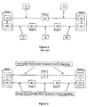
- the Bearer Control Protocol carries a priority indication through the bearer network in the bearer establishment message in order for each switch to recognise the priority of the call. This can be of the form of, say a value of 0-4, with 4 indicating highest priority and 0 indicating lowest priority. Referring to figure 3 , in the AAL type 2 signalling protocol, this is preferably in the simple form of a value of 0 to 4 in the ERQ message.
- Nodes in the bearer network use this value to allocate internal resources and outgoing paths according to particular network conditions. For example, Node 2 can immediately recognise the priority level from the incoming message and route the call to Node 4 along an "emergency-marked" path between the two nodes.
- the call control level priority indication is determined and assigned or mapped to a bearer level priority indication field in a bearer network protocol message.
- the value of the priority indicator in the Q.2630.2 ERQ message is mapped from the BICC Call Control Priority value. This mapping is done in the initiating node, Node 1.
- the invention is embodied by the mapping being performed at any one or a combination of node(s) intermediate a first transmitting node or endpoint and a second receiving node or endpoint for the call. Table 1, below illustrates this mapping.
- a non-switched network such as an IP network
- the Bearer Control Protocol is carried, or tunnelled inside the Call Control Protocol.
- the Bearer Control Protocol is not passed through the bearer network, that is, it is not seen by the routers in the bearer network.
- the protocol allocates resources in the network. Due to the nature of a non-switched network, each user packet, in this case IP packet, carries an indication of the priority in order for each router to be able to route the packet according to the priority.
- Other bearer control protocols can be used as would be understood by a person skilled in the art.
- the call control level priority indication is determined and then assigned or mapped between the BICC Call Control Priority values and the values carried in the IP packet.
- a field already exists in the IP header as an example see RFC791, Internet Protocol (Ipv4), which carries this priority, an 8-value field called "Priority”. This is, in turn, carried inside the "Type of Service” field.
- Ipv4 Internet Protocol
- the present invention may be embodied by this mapping being performed at, or by means within the initiating or transmitting node, for example Node 1.
- the invention may be embodied by the mapping being performed at any one or a combination of node(s) intermediate a first transmitting node or endpoint and a second receiving node or endpoint for the call.
- Table 2 BICC Call Control Priority Value e.g. MLPP value
- IP Precedence Value e.g. in IP Header, Type of Service field
- Flash Override (0) Flash Override (4) Flash (1) Flash (3 Immediate (2) Immediate (2) Priority (3) Priority (1) Normal (4) Routine (0)
- IP Precedence field there are three further values of the IP Precedence field, namely "Network Control (7)", “Internetwork Control (6)", and "CRITIC/ECP (5)" that are not used in the above tabled example.
- IP Precedence field there are three further values of the IP Precedence field, namely "Network Control (7)", “Internetwork Control (6)", and "CRITIC/ECP (5)" that are not used in the above tabled example.
- BICC Priority value for Flash Override (0) is mapped to an IP Priority value for Network Control (7).
- the specifics of this mapping are in accordance with the importance of the particular priority call, network configuration, and current network usage.
- the call control priority level indication is processed from the bearer network level to the call control network level by way of decoding/recovery in which the bearer network priority level is determined and assigned to a call control level priority indication of a call, call message or assigned in accordance with a subscriber profile.
- This process is performed at a second or receiving node or endpoint.
- the process is performed at a node(s) intermediate a first transmitting node and a second receiving node where the intermediate node provides a Call Control function.
Abstract
Description
- The present invention relates generally to telecommunication services and, in particular, to communicating priority indications between telecommunication nodes in a telecommunication system having a separated call control and bearer control architecture.
- For cost-efficiency reasons telecommunication operators are increasingly deploying non-STM (non-Synchronous Transfer Mode) transport technologies inside their networks. Examples of these technologies are ATM (Asynchronous Transfer Mode), IP (Internet Protocol), and FR (Frame Relay). Therefore, a standardised solution is required to support existing services of today's public telecommunication networks over multi-vendor non-STM infrastructures. In the current public telecommunication networks, the call control (CC) and bearer control (BC) are tightly coupled in the same public network protocol, for example, ISUP (ISDN User Part). As a result of this trend to run over multi-vendor non-STM infrastructures, a new network architecture has been developed that allows for the splitting or separating of call control (CC) and bearer control (BC) into separate protocols.
Figures 1a and 1b show the evolution from current integrated CC/BC public network protocols such as ISUP, to the separated CC/BC solution. - The split of CC and BC functions results in a new interface exposed between the CC function and BC function. A protocol is required to enable the coupling between the CC and BC functions when a telecommunications node is implemented in a separated environment. As an example, the International Telecommunications Union - Telecommunications Sector (ITU-T) and the Internet Engineering Task Force (IETF) have defined a Gateway Control Protocol to enable the coupling between the CC and BC functions. This protocol is designed to control multimedia connections from a remote control entity and operatively resides between the CC functionality and the BC functionality, as shown in
figures 1a and 1b . Variants of this protocol are known as H.248 and Q.1950 in the ITU, and Megaco in the IETF. - As a result of the separation of Call Control and Bearer Control, a number of functions which existed in the integrated CC/BC environment require the functionality to be duplicated in the Call Control and the Bearer Control environment. One such function is the "Priority Call" function, which is used, for example, in emergency call situations. The definition of the "Priority Call" function may be found in ITU-T Recommendation I.255.4, Priority Service. In such emergency situations, it is absolutely necessary for emergency calls to progress, but it is not necessary that normal calls progress. Typically, this could be achieved in, for example, one of two ways.
- Firstly, if a node receives an emergency call and it has reached its limit of call throughput, the way to allow this emergency call to progress would be to sacrifice, that is terminate, an existing normal call to free up the resources required for the emergency call. Secondly, a node may reserve a certain percentage, for example 2%, of its resources for use by emergency calls only. This means that normal calls cannot use those particular resources. The consequence of this is that in non-emergency situations, the node is running at a sub-optimal capacity. In the example given in this case, 98%. In both of the above examples, it is necessary for the emergency call to be marked as a priority call so that the node can identify the emergency call as such. In the separated CC/BC architecture discussed above, this applies to both call and bearer control protocols, as illustrated in
Figure 2 . - In the network configuration of
figure 2 , the call and bearer connections are initiated atNode 1 and terminated atNode 5. The call control traverses the network viaNode 3 or path C1-C2 as shown, whereas the bearer control traverses the network viaNodes Node 3 should recognise the call as an emergency call and select its internal resources and outgoing path toNode 5 or path C2, appropriately. Likewise,Node 2 should recognise the fact that the bearer path being requested is related to an emergency call, and thus should select its internal resources and outgoing path toNode 4 or path B2, appropriately. - In a separated CC and BC architecture, only the Call Control protocol has an indication that the call has a certain priority. One method of transporting this priority information in the protocol is by the BICC (Bearer Independent Call Control) Precedence indication.
- BICC is based on ISUP (integrated Services Digital Network User Part. That is, the control part of the Signalling System No. 7 protocol, SS7), which is a combined CC/BC protocol. MLPP (Multi-Level Precedence and Preemption Service) is a function in BICC/ISUP. A detailed description of the MLPP is found at ITU-T Recommendation I.255.3 Multi-level Precedence and Preemption Service (MLPP), and ITU-T Recommendation Q.1902.3, Bearer independent call control protocol (CS2) and Signalling System No. 7 - ISDN user part formats and codes.
- There are currently five Precedence values defined in the BICC protocol, namely flash-override, flash, immediate, priority and routine, which are assigned values 0 to 4 respectively. The Call Control protocol provides for an indication of call priority. Currently the
only way Node 2, or Node 4, is aware that the requested bearer set-up is related to an emergency call is that the request is entered on path B1 (or B2). This requires path reservation at a call set up. It thus requires prior network configuration knowledge inNode 2, and alsoNode 4, which is not always possible or practical in modem switching and non-switching networks, and may require complicated Operation and Maintenance proceduresWO 00/059 13 A1 - It is an object of the present invention to overcome or ameliorate at least one of the problems of the prior art.
- This object is solved by the teaching of the independent claims. Preferred embodiments are shown in the dependent claims.
- In one aspect, the present invention provides a method of communicating a call control level priority indication between a first telecommunications node and a second telecommunications node via a bearer network of a separated call control, bearer control telecommunications network, said method including the steps of:
- 1) determining a call control level priority indication;
- 2) mapping the call control level priority indication to a bearer level priority indication of a priority indication field in a bearer network protocol message in accordance with a priority level of a bearer network protocol;
- 3) transmitting the bearer network protocol message within the bearer network via bearer network nodes intermediate the first and second telecommunications nodes.
- In essence, the present invention stems from the realisation that mapping in accordance with a dedicated relationship, a call control level priority indication to a bearer priority indication in a bearer network protocol message field in accordance with a priority mechanism of the bearer network protocol, allows for an explicit indication of priority at the bearer level in a separated network architecture. Thus, a solution is provided which maps or assigns the call level priority, for example in the form of the BICC Precedence values, to the bearer level.
- The call control level priority indication is preferably determined from at least one of a call set up message, and, a subscriber profile.
- In another aspect, the present invention provides a network node of a telecommunication system, the system including a separated Call Control and Bearer Control architecture, the node including:
- 1) call control level priority determining means adapted to determine a call control level priority indication; and
- 2) logic means adapted to logically map the call control level priority indication to a priority indication field in a bearer network protocol message in accordance with a priority level of a bearer network protocol.
- In still another aspect, the present invention provides a computer program product including:
- a computer useable medium having computer readable program code and computer readable system code embodied on said medium for transliterating a call control message between a first node and a second node within a telecommunication system via a bearer network in a separated call control and bearer control telecommunication network, said computer program product including
- computer readable code within said computer usable medium for:
- determining a call control level priority indication for a call set up message, and
- mapping, in accordance with a dedicated relationship, a call control level priority indication to a bearer priority indication in a bearer network protocol message field in accordance with a priority mechanism of a bearer network protocol.
- The call control level priority indication, in a preferred embodiment is assigned to a received call set up message. In another preferred embodiment the call control level priority indication is assigned in accordance with a subscriber profile.
- The method of the present invention may further include the steps of:
- allocating internal resources of the bearer network for communications the bearer network protocol message dependent on the bearer level priority indication.
- Further, the step of determining the call control level priority indication or the step of mapping the call control level priority indication may be performed at the first telecommunication node or at any node or nodes intermediate the first and second nodes.
- Preferably, at least one of the call control level indication or the corresponding call control level indication is determined in accordance with a first or second predetermined designation, respectively. The first designation, preferably a call control protocol indication and the second designation is, preferably, a bearer protocol indication or bearer control protocol indication.
- Preferably, the call control protocol is the Bearer Independent Call Control (BICC) and the call control level priority indication is an I.255.3 Multi-level Precedence and Pre-emption Service (MLPP) indication, or a new field based on the requirements from the I.255.4 Priority Service.
- In one example, the bearer network may be switched AAL2 bearer network and the bearer network protocol message may be a Q2630.2 AAL2 ERQ message. In another example the bearer network may be a non-switched bearer network and the bearer network protocol message may transmitted by at least one Ipv4 or Ipv6 packet.
- A preferred embodiment of the present invention will now be described with reference to the accompanying drawings, in which:
-
Figures 1 a and 1 b show the evolution from previous integrated Call Control and Bearer Control public network protocols to a separated Call Control and Bearer Control public network architecture. -
Figure 2 shows a separated Call Control and Bearer Control network architecture of the prior art. -
Figure 3 shows an example of call level priority indications communicated via a bearer network in accordance with a first preferred embodiment of the present invention. -
Figure 4 shows an example of call level priority indications communicated via a bearer network in accordance with a second preferred embodiment of the present invention. - An indication of call control level priority may be determined on a call by call basis or in accordance with a predesignated subscriber profile. In the call by call basis example, the call control level priority indication is determined from a call set up message.
- There are two types of bearer network configurations available in the existing telecommunication network specifications of the separated CC and BC architecture. These are switched and non-switched networks. A switched network is one where the bearer path is defined at the time of call set-up, and all user data is transferred along that path for the duration of the call. A non-switched network is one whereby the bearer path is not defined at call set-up, and decisions are made in real-time as to the path that user data is communicated. An example of a switched network is one where the bearer is AAL2 (ATM Adaption layer 2), whereby the bearer is connected through one or more AAL2 switches and the path of the user packets through the switches is defined at the time of call set-up. Detail on the AAL2 bearer protocol is found at ITU-T Recommendation Q.2630.2,
AAL Type 2 Signalling Protocol. Further examples of possible bearer control protocols for a switched network as in a switched BICC network include, AAL1 (ATM Adaption Layer 2), PNNI (Private Network to Network interface), DSS2 (DigitalSubscriber Signaling # 2 for ATM broadband signaling), B-ISUP (Broadband ISUP). An example of a non-switched network is one where the bearer is IP (Internet Protocol), where the user packets are transferred through IP routers, where the path of the user packets through the network is decided by the IP routers in real-time. Detail on the IP bearer protocol is found, for example, at RFC791, Internet Protocol (Ipv4). In a non-switched network, each packet takes a different path through the IP network. Further examples of possible bearer protocols for a non-switched network, as in a non-switched BICC network include, Structured AAL1 (see I.363.1) and Trunked AAL2 (see Q.2630.1, Annex A). A person skilled in the art would recognise that other bearer network protocols can be used in associated with the invention, without departing from the spirit of the present invention. - In a switched bearer network such as an AAL2 switched network, the Bearer Control Protocol is carried through and processed at the switches in the bearer network. The Bearer Control Protocol carries a priority indication through the bearer network in the bearer establishment message in order for each switch to recognise the priority of the call. This can be of the form of, say a value of 0-4, with 4 indicating highest priority and 0 indicating lowest priority. Referring to
figure 3 , in theAAL type 2 signalling protocol, this is preferably in the simple form of a value of 0 to 4 in the ERQ message. Nodes in the bearer network use this value to allocate internal resources and outgoing paths according to particular network conditions. For example,Node 2 can immediately recognise the priority level from the incoming message and route the call toNode 4 along an "emergency-marked" path between the two nodes. - In the present invention, the call control level priority indication is determined and assigned or mapped to a bearer level priority indication field in a bearer network protocol message. In one form, the value of the priority indicator in the Q.2630.2 ERQ message is mapped from the BICC Call Control Priority value. This mapping is done in the initiating node,
Node 1. In other preferred embodiments, the invention is embodied by the mapping being performed at any one or a combination of node(s) intermediate a first transmitting node or endpoint and a second receiving node or endpoint for the call. Table 1, below illustrates this mapping.Table 1 BICC Call Control Priority Value (e.g..MLPP value) Bearer Control Priority Value (e.g. in Q.2630) Flash Override (0) 0 Flash (1) 1 Immediate (2) 2 Priority (3) 3 Normal (4) 4 - Whilst the values can be mapped exactly, it is also within the scope of the invention to set the CC and BC Priority values to different values according to the importance of the particular priority call, network configuration, and current network usage. The person skilled in the art would derive variants without limiting the scope of the invention.
- In a non-switched network, such as an IP network, the Bearer Control Protocol is carried, or tunnelled inside the Call Control Protocol. Detail on an example Bearer Control Protocol for IP networks is found at ITU-T Recommendation Q.1970, BICC IP Bearer Control Protocol. The Bearer Control Protocol is not passed through the bearer network, that is, it is not seen by the routers in the bearer network. The protocol allocates resources in the network. Due to the nature of a non-switched network, each user packet, in this case IP packet, carries an indication of the priority in order for each router to be able to route the packet according to the priority. Other bearer control protocols can be used as would be understood by a person skilled in the art.
- In order to obtain the full priority indication required, which is similar to that of a switched network, the call control level priority indication is determined and then assigned or mapped between the BICC Call Control Priority values and the values carried in the IP packet. A field already exists in the IP header, as an example see RFC791, Internet Protocol (Ipv4), which carries this priority, an 8-value field called "Priority". This is, in turn, carried inside the "Type of Service" field. An example of this mapping is shown below in table 2.
- As in the example of a switched Network, the present invention may be embodied by this mapping being performed at, or by means within the initiating or transmitting node, for
example Node 1. In another preferred embodiment, the invention may be embodied by the mapping being performed at any one or a combination of node(s) intermediate a first transmitting node or endpoint and a second receiving node or endpoint for the call.Table 2 BICC Call Control Priority Value (e.g. MLPP value) IP Precedence Value (e.g. in IP Header, Type of Service field) Flash Override (0) Flash Override (4) Flash (1) Flash (3 Immediate (2) Immediate (2) Priority (3) Priority (1) Normal (4) Routine (0) - As a further example, there are three further values of the IP Precedence field, namely "Network Control (7)", "Internetwork Control (6)", and "CRITIC/ECP (5)" that are not used in the above tabled example. However it is possible to define a mapping from a specific BICC priority value to one of these values. For example, a BICC Priority value for Flash Override (0), is mapped to an IP Priority value for Network Control (7). As in the switched network case, the specifics of this mapping are in accordance with the importance of the particular priority call, network configuration, and current network usage.
- The call control level priority indication is determined by a first designation. The bearer level priority indication is determined by a second designation. Tables 1 and 2 above provide examples. Furthermore, the first designation can be a BICC indication and the second designation can be a bearer network control Protocol indication. A skilled person would understand that variations are possible within the scope of the present invention.
- In a further embodiment of the present invention, the call control priority level indication is processed from the bearer network level to the call control network level by way of decoding/recovery in which the bearer network priority level is determined and assigned to a call control level priority indication of a call, call message or assigned in accordance with a subscriber profile. This process is performed at a second or receiving node or endpoint. In a further embodiment, the process is performed at a node(s) intermediate a first transmitting node and a second receiving node where the intermediate node provides a Call Control function.
Claims (35)
- A method of communicating a call control level priority indication between a first
telecommunications node and a second telecommunications node via a bearer network of a separated call control, bearer control telecommunications network, including the steps of:1) determining a call control level priority indication;2) mapping the call control level priority indication to a bearer level priority indication of a priority indication field in a bearer network protocol message in accordance with a priority level of a bearer network protocol;3) transmitting the bearer network protocol message within the bearer network via bearer network nodes intermediate the first and second telecommunication nodes. - A method as claimed in claim 1, wherein the call control level priority indication is determined from a call set up message.
- A method as claimed in claim 1, wherein the call control level priority indication is determined from a subscriber profile.
- A method as claimed in claim 1, 2 or 3, further including the step of:allocating internal resources of the bearer network for communicating the bearer network protocol message dependent on the bearer level priority indication.
- A method as claimed in any one of claims 1 to 4, wherein at least one of the steps of determining the call control level priority indication and mapping the call control level priority indication to a bearer level priority indication is performed at the first telecommunication node.
- A method as claimed in any one of claims 1 to 5, wherein at least one of the steps of determining the call control level priority indication and mapping the call control level priority indication to a bearer level priority indication is performed at a node(s) intermediate the first node and the second node.
- A method as claimed in any one of claims 1 to 6, wherein the bearer network is a switched bearer network and the bearer network protocol message is a switched bearer network protocol message.
- A method as claimed in any one of claims 1 to 6, wherein the bearer network is a non-switched bearer network and the bearer network protocol message is a non-switched bearer network protocol message.
- A method as claimed in any one of the previous claims wherein, the call control level priority indication is determined in accordance with a first predetermined designation.
- A method as claimed in any one of the previous claims, wherein, the bearer level priority indication is determined in accordance with a second predetermined designation.
- A method as claimed in claim 9 or 10, wherein the first predetermined designation is a Bearer Independent Call Control, BlCC, protocol indication and the call control level priority indication is at least one of a Multi-level Precedence and Pre-emption Service, MLPP, indication, and an indication based on requirements of a Priority Service.
- A method as claimed in claims 10 or 11, wherein the second predetermined designation is at least one of a bearer network control protocol indication and a bearer network protocol indication, and the call control level priority indication is at least one of a Multi-Level Precedence and Pre-emption service, MLPP, indication, and an indication based on requirements of a Priority Service.
- A network node of a telecommunication system, the system including a separated Call Control and Bearer Control architecture, the node including:1) call control level priority determining means adapted to determine a call control level priority indication; and2) logic means adapted to logically map the call control level priority indication to a priority indication field in a bearer network protocol message in accordance with a priority level of a bearer network protocol.
- A network node as claimed in claim 13, wherein the call control level priority indication is determined from a call set up message.
- A network node as claimed in claim 13, wherein the call control level priority indication is determined from a subscriber profile.
- A network node as claimed in claim 13, 14 or 15, adapted to allocate internal resources of the bearer network for communicating the bearer network protocol message dependent on the bearer level priority indication.
- A network node as claimed in any one of claims 13 to 16, wherein the node is the first node in the network.
- A network node as claimed in any one of claims 13 to 17, wherein the bearer network is a switched bearer network and the bearer network protocol message is a switched bearer network protocol message.
- A network node as claimed in any one of claims 13 to 17, wherein the bearer network is a non-switched bearer network and the bearer network protocol message is a non-switched bearer network protocol message.
- A network node as claimed in any one of claims 13 to 19 wherein, the call control level priority indication is determined in accordance with a first predetermined designation.
- A network node as claimed in any one of claims 13 to 20, wherein, the bearer level priority indication is determined in accordance with a second predetermined designation.
- A network node as claimed in claim 20 or claim 21, wherein the first predetermined designation is a Bearer Independent Call Control, BlCC, protocol indication and the call control level priority indication is at least one of a Multi-level Precedence and Pre-emption Service, MLPP, indication, and an indication based on requirements of a Priority Service.
- A network node as claimed in claims 21 or 22, wherein the second predetermined designation is at least one of a bearer network control protocol indication and a bearer network protocol indication, and the call control level priority indication is at least one of a Multi-Level Precedence and Pre-emption service, MLPP, indication, and an indication based on requirements of a Priority Service.
- A computer program product including:a computer usable medium having computer readable program code and computer readable system code embodied on said medium for transliterating a call control message between a first node and a second node within a telecommunication system via a bearer network in a separated call control and bearer control telecommunication network, said computer program product includingcomputer readable code within said computer usable medium for:determining a call control level priority indication for a call set up message, andmapping, in accordance with a dedicated relationship, said call control level priority indication to a bearer priority indication in a bearer network protocol message field in accordance with a priority mechanism of a bearer network protocol.
- A computer program product as claimed in claim 24, wherein the call control level priority indication is determined from the call set up message.
- A computer program product as claimed in claims 24, wherein the call control level priority indication is determined from a subscriber profile.
- A computer program product as claimed in claim 24, 25 or 26, said computer program product further including computer readable code within said computer usable medium for allocating internal resources of the bearer network for communicating the bearer network protocol message dependent on the bearer level priority indication.
- A computer program product as claimed in any one of claims 24 to 27, wherein at least one of the steps of determining the call control level priority indication and mapping the call control level priority indication to a bearer level priority indication is performed at the first telecommunication node.
- A computer program product as claimed in any one of claims 24 to 28, wherein at least one of the steps of determining the call control level priority indication and mapping the call control level priority indication to a bearer level priority indication is performed at a node(s) intermediate the first node and the second node.
- A computer program product as claimed in any one of claims 24 to 29, wherein the bearer network is a switched bearer network and the bearer network protocol message is a switched bearer network protocol message.
- A computer program product as claimed in any one of claims 24 to 29, wherein the bearer network is a non-switched bearer network and the bearer network protocol message is a non-switched bearer network protocol message.
- A computer program product as claimed in any one of claims 24 to 31 wherein, the call control level priority indication is determined in accordance with a first predetermined designation.
- A computer program product as claimed in any one of claims 24 to 32 wherein, the bearer level priority indication is determined in accordance with a second predetermined designation.
- A computer program product as claimed in claim 32 or 33, wherein the first predetermined designation is a Bearer Independent Call Control, BlCC, protocol indication and the call control level priority indication is at least one of a Multi-level Precedence and Pre-emption Service, MLPP, indication, and an indication based on requirements of a Priority Service.
- A computer program product as claimed in claims 33 or 34, wherein the second predetermined designation is at least one of a bearer network control protocol indication and a bearer network protocol indication, and the call control level priority indication is at least one of a Multi-Level Precedence and Preemption service, MLPP, indication, and an indication based on requirements of a Priority Service.
Priority Applications (1)
| Application Number | Priority Date | Filing Date | Title |
|---|---|---|---|
| EP10012237A EP2378787A3 (en) | 2001-11-12 | 2001-11-12 | Priority indication in a separated call and bearer control architecture |
Applications Claiming Priority (1)
| Application Number | Priority Date | Filing Date | Title |
|---|---|---|---|
| PCT/IB2001/002118 WO2003043368A1 (en) | 2001-11-12 | 2001-11-12 | A system and method of communicating a priority indication in a call control/bearer control telecommunication system |
Related Child Applications (1)
| Application Number | Title | Priority Date | Filing Date |
|---|---|---|---|
| EP10012237.3 Division-Into | 2010-09-30 |
Publications (2)
| Publication Number | Publication Date |
|---|---|
| EP1444854A1 EP1444854A1 (en) | 2004-08-11 |
| EP1444854B1 true EP1444854B1 (en) | 2011-03-16 |
Family
ID=11004206
Family Applications (2)
| Application Number | Title | Priority Date | Filing Date |
|---|---|---|---|
| EP10012237A Withdrawn EP2378787A3 (en) | 2001-11-12 | 2001-11-12 | Priority indication in a separated call and bearer control architecture |
| EP01982645A Expired - Lifetime EP1444854B1 (en) | 2001-11-12 | 2001-11-12 | A system and method of communicating a priority indication in a call control/bearer control telecommunication system |
Family Applications Before (1)
| Application Number | Title | Priority Date | Filing Date |
|---|---|---|---|
| EP10012237A Withdrawn EP2378787A3 (en) | 2001-11-12 | 2001-11-12 | Priority indication in a separated call and bearer control architecture |
Country Status (6)
| Country | Link |
|---|---|
| US (2) | US7912079B2 (en) |
| EP (2) | EP2378787A3 (en) |
| AT (1) | ATE502486T1 (en) |
| DE (1) | DE60144250D1 (en) |
| PT (1) | PT1444854E (en) |
| WO (1) | WO2003043368A1 (en) |
Families Citing this family (5)
| Publication number | Priority date | Publication date | Assignee | Title |
|---|---|---|---|---|
| CN101146052B (en) * | 2005-04-25 | 2011-04-20 | 华为技术有限公司 | Method for processing emergent service in network communication |
| CN100479374C (en) * | 2005-04-25 | 2009-04-15 | 华为技术有限公司 | Method for processing urgent business in network communication |
| US20090104916A1 (en) * | 2007-09-26 | 2009-04-23 | Nokia Siemens Networks Oy | Method, apparatus and system for signalling of buffer status information |
| US8537999B1 (en) | 2011-09-09 | 2013-09-17 | Cisco Technology, Inc. | Managing precedence call preemption in a communication environment |
| EP3103281B1 (en) * | 2014-02-06 | 2020-01-01 | Telefonaktiebolaget LM Ericsson (publ) | Multi-bearer connection control |
Family Cites Families (28)
| Publication number | Priority date | Publication date | Assignee | Title |
|---|---|---|---|---|
| FR2694466B1 (en) * | 1992-07-29 | 1994-09-02 | Cit Alcatel | Telecommunication network carrying out call processing and connection processing separately. |
| GB9418772D0 (en) * | 1994-09-16 | 1994-11-02 | Ionica L3 Limited | Digital telephony |
| GB9621524D0 (en) * | 1996-10-16 | 1996-12-04 | British Telecomm | Multimedia call centre |
| US6449284B1 (en) * | 1997-03-21 | 2002-09-10 | Avaya Technology Corp. | Methods and means for managing multimedia call flow |
| CA2411996C (en) * | 1997-04-24 | 2009-09-08 | Ntt Mobile Communications Network Inc. | Method and system for mobile communications |
| US6160818A (en) * | 1997-07-17 | 2000-12-12 | At &T Corp | Traffic management in packet communication networks having service priorities and employing effective bandwidths |
| US6608832B2 (en) * | 1997-09-25 | 2003-08-19 | Telefonaktiebolaget Lm Ericsson | Common access between a mobile communications network and an external network with selectable packet-switched and circuit-switched and circuit-switched services |
| US6418461B1 (en) * | 1997-10-06 | 2002-07-09 | Mci Communications Corporation | Intelligent call switching node in an intelligent distributed network architecture |
| FI108507B (en) * | 1998-07-23 | 2002-01-31 | Nokia Corp | Method and arrangement for managing connections |
| FI107505B (en) * | 1999-02-16 | 2001-08-15 | Nokia Networks Oy | Access control procedure |
| US6618378B1 (en) * | 1999-07-21 | 2003-09-09 | Alcatel Canada Inc. | Method and apparatus for supporting multiple class of service connections in a communications network |
| EP1079582A1 (en) * | 1999-08-20 | 2001-02-28 | Telefonaktiebolaget L M Ericsson (Publ) | Service parameter interworking method |
| JP2001237855A (en) * | 2000-02-25 | 2001-08-31 | Fujitsu Ltd | Switching system and its routing method |
| GB0009226D0 (en) * | 2000-04-12 | 2000-05-31 | Nokia Networks Oy | Transporting information in a communication system |
| DE10022089A1 (en) * | 2000-05-08 | 2001-11-22 | Deutsche Telekom Mobil | Automatic call priority control method for automatic call distribution unit identifies priority caller and controls call handling dependent on priority level |
| US7072329B2 (en) * | 2000-05-22 | 2006-07-04 | Telefonaktiebolaget Lm Ericsson (Publ) | Combining differing transport technologies in a telecommunications system |
| US6765912B1 (en) * | 2000-08-08 | 2004-07-20 | Nortel Networks Limited | Network resource usage in call sessions |
| US7002919B1 (en) * | 2000-08-16 | 2006-02-21 | Lucent Technologies Inc. | Method and system for guaranteeing quality of service for voice-over-IP services |
| US20030125041A1 (en) * | 2000-08-29 | 2003-07-03 | Friedrich Stippel | Method for establishing communication relations |
| US7546376B2 (en) * | 2000-11-06 | 2009-06-09 | Telefonaktiebolaget Lm Ericsson (Publ) | Media binding to coordinate quality of service requirements for media flows in a multimedia session with IP bearer resources |
| EP1259037A1 (en) * | 2001-05-18 | 2002-11-20 | TELEFONAKTIEBOLAGET L M ERICSSON (publ) | Method and devices for the interworking of nodes |
| EP1324544A1 (en) * | 2001-12-26 | 2003-07-02 | Telefonaktiebolaget L M Ericsson (Publ) | Method and system for controlling traffic load between media gateway controllers and proxies |
| JP3871604B2 (en) * | 2002-04-30 | 2007-01-24 | 富士通株式会社 | VoIP network system |
| US7532647B2 (en) * | 2004-07-14 | 2009-05-12 | Tekelec | Methods and systems for auto-correlating message transfer part (MTP) priority and internet protocol (IP) type of service in converged networks |
| JP2009111498A (en) * | 2007-10-26 | 2009-05-21 | Nec Corp | Radio controller, radio base station, radio communication system, call admission control method, program and recording medium |
| US8184002B2 (en) * | 2008-07-28 | 2012-05-22 | Huawei Technologies Co., Ltd. | Method and device for receiving emergency event alert |
| JP4742171B2 (en) * | 2010-01-06 | 2011-08-10 | 株式会社エヌ・ティ・ティ・ドコモ | Mobile communication method, call control node, priority control node, and mobility management node |
| US8792340B2 (en) * | 2010-06-14 | 2014-07-29 | Alcatel Lucent | Admission control for shared LTE network |
-
2001
- 2001-11-12 EP EP10012237A patent/EP2378787A3/en not_active Withdrawn
- 2001-11-12 AT AT01982645T patent/ATE502486T1/en not_active IP Right Cessation
- 2001-11-12 WO PCT/IB2001/002118 patent/WO2003043368A1/en not_active Application Discontinuation
- 2001-11-12 DE DE60144250T patent/DE60144250D1/en not_active Expired - Lifetime
- 2001-11-12 US US10/494,831 patent/US7912079B2/en active Active
- 2001-11-12 PT PT01982645T patent/PT1444854E/en unknown
- 2001-11-12 EP EP01982645A patent/EP1444854B1/en not_active Expired - Lifetime
-
2011
- 2011-02-08 US US13/022,761 patent/US9049052B2/en not_active Expired - Lifetime
Also Published As
| Publication number | Publication date |
|---|---|
| US7912079B2 (en) | 2011-03-22 |
| EP1444854A1 (en) | 2004-08-11 |
| US20050013315A1 (en) | 2005-01-20 |
| EP2378787A3 (en) | 2012-01-11 |
| PT1444854E (en) | 2011-06-29 |
| ATE502486T1 (en) | 2011-04-15 |
| US9049052B2 (en) | 2015-06-02 |
| US20110216761A1 (en) | 2011-09-08 |
| WO2003043368A1 (en) | 2003-05-22 |
| DE60144250D1 (en) | 2011-04-28 |
| EP2378787A2 (en) | 2011-10-19 |
Similar Documents
| Publication | Publication Date | Title |
|---|---|---|
| EP1069742B1 (en) | Method and architecture to support multiple services in label switched networks | |
| JP4889174B2 (en) | Service parameter network connection method | |
| CA2351774C (en) | Communications network | |
| US6507577B1 (en) | Voice over internet protocol network architecture | |
| US7710873B2 (en) | Interaction in a communication system | |
| US7002935B2 (en) | Real time data transmission systems and methods | |
| EP1192791B1 (en) | Voip using ss7 signalling and cooperation of ip nodes with signalling points | |
| JP2000196664A (en) | Method for providing service quality for traffic sensitive to delay transmitted on internet network | |
| US6021136A (en) | Telecommunication network that reduces tandeming of compressed voice packets | |
| US7200110B1 (en) | Method and apparatus for prioritized release of connections in a communications network | |
| US9049052B2 (en) | System and method of communicating a priority indication in a call control/bearer control telecommunication system | |
| US8265696B1 (en) | Digital telecommunication system | |
| US6928069B2 (en) | Bandwidth management apparatus, address resolution assistance apparatus, method for managing bandwidth, and method for assisting address resolution | |
| EP1676408B1 (en) | Call control using a layered call model | |
| US20040052256A1 (en) | Method for transmitting data packets in a cellular communication network | |
| US7254130B1 (en) | Predictively allocated bandwidth in a communications network | |
| JP2000324177A (en) | Method and device for connecting networks | |
| Cherukuri et al. | Frame relay: protocols and private network applications | |
| AU725361B2 (en) | A method of transmitting an ATM cell over an ATM network | |
| WO2001011825A2 (en) | Communications using hybrid circuit-switched and packet-switched networks | |
| KR100204046B1 (en) | Method for setting the field arameter of broadband bearer capability information factor in atm exchange system |
Legal Events
| Date | Code | Title | Description |
|---|---|---|---|
| PUAI | Public reference made under article 153(3) epc to a published international application that has entered the european phase |
Free format text: ORIGINAL CODE: 0009012 |
|
| 17P | Request for examination filed |
Effective date: 20040507 |
|
| AK | Designated contracting states |
Kind code of ref document: A1 Designated state(s): AT BE CH CY DE DK ES FI FR GB GR IE IT LI LU MC NL PT SE TR |
|
| AX | Request for extension of the european patent |
Extension state: AL LT LV MK RO SI |
|
| RAP1 | Party data changed (applicant data changed or rights of an application transferred) |
Owner name: TELEFONAKTIEBOLAGET LM ERICSSON (PUBL) |
|
| 17Q | First examination report despatched |
Effective date: 20070412 |
|
| RIC1 | Information provided on ipc code assigned before grant |
Ipc: H04Q 3/00 20060101AFI20100721BHEP Ipc: H04L 12/56 20060101ALN20100721BHEP |
|
| GRAP | Despatch of communication of intention to grant a patent |
Free format text: ORIGINAL CODE: EPIDOSNIGR1 |
|
| GRAS | Grant fee paid |
Free format text: ORIGINAL CODE: EPIDOSNIGR3 |
|
| GRAA | (expected) grant |
Free format text: ORIGINAL CODE: 0009210 |
|
| AK | Designated contracting states |
Kind code of ref document: B1 Designated state(s): AT BE CH CY DE DK ES FI FR GB GR IE IT LI LU MC NL PT SE TR |
|
| REG | Reference to a national code |
Ref country code: GB Ref legal event code: FG4D |
|
| REG | Reference to a national code |
Ref country code: CH Ref legal event code: EP Ref country code: CH Ref legal event code: NV Representative=s name: ISLER & PEDRAZZINI AG |
|
| REG | Reference to a national code |
Ref country code: IE Ref legal event code: FG4D |
|
| REF | Corresponds to: |
Ref document number: 60144250 Country of ref document: DE Date of ref document: 20110428 Kind code of ref document: P |
|
| REG | Reference to a national code |
Ref country code: DE Ref legal event code: R096 Ref document number: 60144250 Country of ref document: DE Effective date: 20110428 |
|
| REG | Reference to a national code |
Ref country code: PT Ref legal event code: SC4A Free format text: AVAILABILITY OF NATIONAL TRANSLATION Effective date: 20110614 Ref country code: NL Ref legal event code: T3 |
|
| PG25 | Lapsed in a contracting state [announced via postgrant information from national office to epo] |
Ref country code: GR Free format text: LAPSE BECAUSE OF FAILURE TO SUBMIT A TRANSLATION OF THE DESCRIPTION OR TO PAY THE FEE WITHIN THE PRESCRIBED TIME-LIMIT Effective date: 20110617 Ref country code: ES Free format text: LAPSE BECAUSE OF FAILURE TO SUBMIT A TRANSLATION OF THE DESCRIPTION OR TO PAY THE FEE WITHIN THE PRESCRIBED TIME-LIMIT Effective date: 20110627 Ref country code: SE Free format text: LAPSE BECAUSE OF FAILURE TO SUBMIT A TRANSLATION OF THE DESCRIPTION OR TO PAY THE FEE WITHIN THE PRESCRIBED TIME-LIMIT Effective date: 20110316 |
|
| PG25 | Lapsed in a contracting state [announced via postgrant information from national office to epo] |
Ref country code: CY Free format text: LAPSE BECAUSE OF FAILURE TO SUBMIT A TRANSLATION OF THE DESCRIPTION OR TO PAY THE FEE WITHIN THE PRESCRIBED TIME-LIMIT Effective date: 20110316 Ref country code: AT Free format text: LAPSE BECAUSE OF FAILURE TO SUBMIT A TRANSLATION OF THE DESCRIPTION OR TO PAY THE FEE WITHIN THE PRESCRIBED TIME-LIMIT Effective date: 20110316 Ref country code: FI Free format text: LAPSE BECAUSE OF FAILURE TO SUBMIT A TRANSLATION OF THE DESCRIPTION OR TO PAY THE FEE WITHIN THE PRESCRIBED TIME-LIMIT Effective date: 20110316 |
|
| PG25 | Lapsed in a contracting state [announced via postgrant information from national office to epo] |
Ref country code: BE Free format text: LAPSE BECAUSE OF FAILURE TO SUBMIT A TRANSLATION OF THE DESCRIPTION OR TO PAY THE FEE WITHIN THE PRESCRIBED TIME-LIMIT Effective date: 20110316 |
|
| PLBE | No opposition filed within time limit |
Free format text: ORIGINAL CODE: 0009261 |
|
| STAA | Information on the status of an ep patent application or granted ep patent |
Free format text: STATUS: NO OPPOSITION FILED WITHIN TIME LIMIT |
|
| 26N | No opposition filed |
Effective date: 20111219 |
|
| PG25 | Lapsed in a contracting state [announced via postgrant information from national office to epo] |
Ref country code: DK Free format text: LAPSE BECAUSE OF FAILURE TO SUBMIT A TRANSLATION OF THE DESCRIPTION OR TO PAY THE FEE WITHIN THE PRESCRIBED TIME-LIMIT Effective date: 20110316 |
|
| REG | Reference to a national code |
Ref country code: DE Ref legal event code: R097 Ref document number: 60144250 Country of ref document: DE Effective date: 20111219 |
|
| PG25 | Lapsed in a contracting state [announced via postgrant information from national office to epo] |
Ref country code: IT Free format text: LAPSE BECAUSE OF FAILURE TO SUBMIT A TRANSLATION OF THE DESCRIPTION OR TO PAY THE FEE WITHIN THE PRESCRIBED TIME-LIMIT Effective date: 20110316 |
|
| PG25 | Lapsed in a contracting state [announced via postgrant information from national office to epo] |
Ref country code: MC Free format text: LAPSE BECAUSE OF NON-PAYMENT OF DUE FEES Effective date: 20111130 |
|
| REG | Reference to a national code |
Ref country code: IE Ref legal event code: MM4A |
|
| PG25 | Lapsed in a contracting state [announced via postgrant information from national office to epo] |
Ref country code: IE Free format text: LAPSE BECAUSE OF NON-PAYMENT OF DUE FEES Effective date: 20111112 |
|
| PG25 | Lapsed in a contracting state [announced via postgrant information from national office to epo] |
Ref country code: LU Free format text: LAPSE BECAUSE OF NON-PAYMENT OF DUE FEES Effective date: 20111112 |
|
| PG25 | Lapsed in a contracting state [announced via postgrant information from national office to epo] |
Ref country code: TR Free format text: LAPSE BECAUSE OF FAILURE TO SUBMIT A TRANSLATION OF THE DESCRIPTION OR TO PAY THE FEE WITHIN THE PRESCRIBED TIME-LIMIT Effective date: 20110316 |
|
| PGFP | Annual fee paid to national office [announced via postgrant information from national office to epo] |
Ref country code: CH Payment date: 20141127 Year of fee payment: 14 Ref country code: DE Payment date: 20141128 Year of fee payment: 14 Ref country code: GB Payment date: 20141127 Year of fee payment: 14 Ref country code: FR Payment date: 20141118 Year of fee payment: 14 |
|
| PGFP | Annual fee paid to national office [announced via postgrant information from national office to epo] |
Ref country code: PT Payment date: 20141022 Year of fee payment: 14 |
|
| PGFP | Annual fee paid to national office [announced via postgrant information from national office to epo] |
Ref country code: NL Payment date: 20151126 Year of fee payment: 15 |
|
| REG | Reference to a national code |
Ref country code: PT Ref legal event code: MM4A Free format text: LAPSE DUE TO NON-PAYMENT OF FEES Effective date: 20160512 |
|
| REG | Reference to a national code |
Ref country code: DE Ref legal event code: R119 Ref document number: 60144250 Country of ref document: DE |
|
| REG | Reference to a national code |
Ref country code: CH Ref legal event code: PL |
|
| GBPC | Gb: european patent ceased through non-payment of renewal fee |
Effective date: 20151112 |
|
| PG25 | Lapsed in a contracting state [announced via postgrant information from national office to epo] |
Ref country code: LI Free format text: LAPSE BECAUSE OF NON-PAYMENT OF DUE FEES Effective date: 20151130 Ref country code: CH Free format text: LAPSE BECAUSE OF NON-PAYMENT OF DUE FEES Effective date: 20151130 |
|
| REG | Reference to a national code |
Ref country code: FR Ref legal event code: ST Effective date: 20160729 |
|
| PG25 | Lapsed in a contracting state [announced via postgrant information from national office to epo] |
Ref country code: PT Free format text: LAPSE BECAUSE OF NON-PAYMENT OF DUE FEES Effective date: 20160512 |
|
| PG25 | Lapsed in a contracting state [announced via postgrant information from national office to epo] |
Ref country code: DE Free format text: LAPSE BECAUSE OF NON-PAYMENT OF DUE FEES Effective date: 20160601 Ref country code: GB Free format text: LAPSE BECAUSE OF NON-PAYMENT OF DUE FEES Effective date: 20151112 |
|
| PG25 | Lapsed in a contracting state [announced via postgrant information from national office to epo] |
Ref country code: FR Free format text: LAPSE BECAUSE OF NON-PAYMENT OF DUE FEES Effective date: 20151130 |
|
| REG | Reference to a national code |
Ref country code: NL Ref legal event code: MM Effective date: 20161201 |
|
| PG25 | Lapsed in a contracting state [announced via postgrant information from national office to epo] |
Ref country code: NL Free format text: LAPSE BECAUSE OF NON-PAYMENT OF DUE FEES Effective date: 20161201 |