EP1443745A1 - Image reader - Google Patents
Image reader Download PDFInfo
- Publication number
- EP1443745A1 EP1443745A1 EP02801525A EP02801525A EP1443745A1 EP 1443745 A1 EP1443745 A1 EP 1443745A1 EP 02801525 A EP02801525 A EP 02801525A EP 02801525 A EP02801525 A EP 02801525A EP 1443745 A1 EP1443745 A1 EP 1443745A1
- Authority
- EP
- European Patent Office
- Prior art keywords
- unit
- resolution
- lens
- optical axis
- mirror
- Prior art date
- Legal status (The legal status is an assumption and is not a legal conclusion. Google has not performed a legal analysis and makes no representation as to the accuracy of the status listed.)
- Withdrawn
Links
Images






Classifications
-
- H—ELECTRICITY
- H04—ELECTRIC COMMUNICATION TECHNIQUE
- H04N—PICTORIAL COMMUNICATION, e.g. TELEVISION
- H04N1/00—Scanning, transmission or reproduction of documents or the like, e.g. facsimile transmission; Details thereof
- H04N1/04—Scanning arrangements, i.e. arrangements for the displacement of active reading or reproducing elements relative to the original or reproducing medium, or vice versa
- H04N1/0402—Scanning different formats; Scanning with different densities of dots per unit length, e.g. different numbers of dots per inch (dpi); Conversion of scanning standards
-
- H—ELECTRICITY
- H04—ELECTRIC COMMUNICATION TECHNIQUE
- H04N—PICTORIAL COMMUNICATION, e.g. TELEVISION
- H04N1/00—Scanning, transmission or reproduction of documents or the like, e.g. facsimile transmission; Details thereof
- H04N1/04—Scanning arrangements, i.e. arrangements for the displacement of active reading or reproducing elements relative to the original or reproducing medium, or vice versa
- H04N1/0402—Scanning different formats; Scanning with different densities of dots per unit length, e.g. different numbers of dots per inch (dpi); Conversion of scanning standards
- H04N1/0408—Different densities of dots per unit length
-
- H—ELECTRICITY
- H04—ELECTRIC COMMUNICATION TECHNIQUE
- H04N—PICTORIAL COMMUNICATION, e.g. TELEVISION
- H04N1/00—Scanning, transmission or reproduction of documents or the like, e.g. facsimile transmission; Details thereof
- H04N1/04—Scanning arrangements, i.e. arrangements for the displacement of active reading or reproducing elements relative to the original or reproducing medium, or vice versa
- H04N1/0402—Scanning different formats; Scanning with different densities of dots per unit length, e.g. different numbers of dots per inch (dpi); Conversion of scanning standards
- H04N1/042—Details of the method used
- H04N1/0435—Optical element switching, e.g. switching lenses into a single optical path
Definitions
- This invention relates to an image reading apparatus, and more particularly to an image reading apparatus which has two lenses and read an image at any one of three resolutions which are realized by moving the two lenses.
- Various image reading apparatuses such as scanners include a device with particularly high resolutions (hereinafter referred to as a high-resolution scanner).
- a high-resolution scanner can typically switch among several resolutions, for example, 700 dpi, 2400 dpi, and 4000 dpi. Since each of these three resolutions requires a lens for reading with its resolution, three lenses are required in a case that the resolutions are switched with such three levels, for example. The price of a lens usually increases with resolution.
- switching of resolutions results in reduction in its readable region. The resultant readable region is limited to a central portion in the width direction (main scanning direction) of its document table (platen glass).
- the high-resolution scanner requires the same number of lenses as that of resolutions to be switched.
- the lenses are very expensive and then the high-resolution scanner is also expensive. In particular, this tendency may become more pronounced in a scanner that provides higher resolutions in multiple numbers.
- An image reading apparatus of the present invention comprises a lens unit having a low-resolution lens, a high-resolution lens and a first driving unit to drive the lenses, and a second driving unit to drive the lens unit.
- the first driving unit drives the low-resolution lens and high-resolution lens
- the second driving unit drives the lens unit, whereby the low-resolution lens is placed on the optical axis at a first location and the high-resolution lens is placed off the optical axis.
- the first driving unit drives the low-resolution lens and high-resolution lens and the second driving unit drives the lens unit, whereby the low-resolution lens is placed off the optical axis and the high-resolution lens is placed on the optical axis at a second location.
- the first driving unit drives the low-resolution lens and high-resolution lens and the second driving unit drives the lens unit, whereby the low-resolution lens is placed off the optical axis and the high-resolution lens is placed on the optical axis at a third location.
- the two lenses of low-resolution and high resolution can provide the first through third resolutions (that is, three focuses).
- the single high-resolution lens can provide the second and third resolutions. Therefore, the number of lenses can be reduced to the number which is smaller than that of the resolutions to be switched. This can reduce the price of the image reading apparatus satisfactorily.
- the higher second and third resolutions can be achieved with the single lens, many different resolutions can be provided without the need for more expensive lenses. This can also reduce the price of the image reading apparatus more effectively.
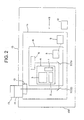
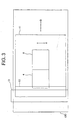
- FIGS. 1 through 3 show the configuration of an image reading apparatus and schematically show the configuration of an image reading apparatus according to the present invention. More specifically, FIG. 1 is a block diagram of the image reading apparatus, FIG. 2 is a schematic cross section of the image reading apparatus, and FIG. 3 is a schematic plan view of the image reading apparatus.
- the image reading apparatus comprises a flatbed-type high-resolution scanner (hereinafter referred to as a high-resolution scanner) having a document table 15 on its top.
- the document table 15 comprises a platen glass, for example.
- the platen glass is provided to the frame (housing 100 of the high-resolution scanner) in a removable manner. This may allow the user to clean out dirt and dust inside the housing 100 of the high-resolution scanner. Replacement of the platen glass will be described later.
- the high-resolution scanner comprises a control unit 16.
- the control unit 16 controls first through fourth driving units 3, 5, 9, 12 as described below to move their driving targets in a predetermined direction by a predetermined distance for reading an image on a medium, respectively.
- the high-resolution scanner comprises a lens unit 4.
- the lens unit 4 comprises a low-resolution lens 1, a high-resolution lens 2, and the first driving unit 3.
- the low-resolution lens 1 is used for a reading operation with a resolution of 700 dpi, for example, at a first location, as described below.
- the high-resolution lens 2 is used for a reading operation with a resolution of 2400 dpi, for example, at a second location and for a reading operation with a resolution of 4000 dpi, for example, at a third location, as described below.
- the lenses 1 and 2 move to provide the predetermined resolutions as described below.
- the first driving unit 3 drives the lenses 1 and 2.
- the first driving unit 3 comprises a driving mechanism including such as a motor, a rack, and gears (not shown). The lenses 1 and 2 are moved into a predetermined direction by the first driving unit 3.
- the high-resolution scanner comprises an optical unit 8.
- the lens unit 4 is part of the optical unit 8. More specifically, the optical unit 8 has, as shown in FIG. 4A etc., the lens unit 4, the second driving unit 5 (not shown in FIG. 4A), a CCD sensor unit 6, and at least first and second mirrors 7 (71, 72).
- the lens unit 4 moves to provide the predetermined resolutions as described below.
- the second driving unit 5 drives the lens unit 4.
- the lens unit 4 is moved into a predetermined direction by the second driving unit 5.
- the CCD sensor unit 6 is a line sensor which comprises a well-known charge-coupled device (CCD), reads an image on a medium placed on the document table 15, and provides output image data (electronic data).
- CCD charge-coupled device
- the second driving unit 5 comprises a driving mechanism including such as a motor, a rack, and gears (not shown).
- a driving mechanism including such as a motor, a rack, and gears (not shown).
- the motor for the first driving unit 3 is also used as the motor for the second driving unit 5.
- the first mirror 71 turns the direction of the optical axis (indicated by a dotted line in FIG. 2) in the optical unit 8.
- the second mirror 72 turns the direction of the optical axis in the flatbed carrier 11. More specifically, the first mirror 71 turns light from the second mirror 72 substantially by a right angle to project it onto the CCD sensor unit 6, and the second mirror 72 turns light from a light source substantially by a right angle onto the first mirror 71.
- the light from the light source is light which is supplied by a transparency lamp unit 13 and passes through a transparency-film document or light which is supplied by a reflection lamp unit 10 and reflected by a reflection-copy document.
- the optical axis is positioned so that it may connect the CCD sensor unit 6 with the first mirror 71 and the first mirror 71 with the second mirror 72 during a reading operation.
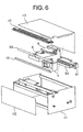
- FIG. 6 shows a specific example of the configuration of the optical unit 8 and the lens unit 4 and
- FIG. 7 shows the configuration of the lens unit 4 in part.
- the optical unit 8 is housed within the flatbed carrier 11 as described below.
- the optical unit 8 is driven by an X motor 91 (and a belt) in the main scanning direction (X direction), along with the guide of two X shafts 92, 93.
- the X motor 91 and the X shafts 92, 93 constitute the driving unit 9.
- the CCD sensor unit 6 is integrally provided to the optical unit 8 and moves together therewith.
- the second mirror 72 is fixed within the flatbed carrier 11 and is provided throughout the whole range in the main scanning direction.
- the reflection lamp unit 10 is also fixed within the flatbed carrier 11 and is provided throughout the whole range in the main scanning direction.
- the optical unit 8 moves throughout the whole range in the main scanning direction.
- the readable region is limited to a central portion in the main scanning direction. Specifically, the readable region is physically substantially equal to the CCD sensor unit 6 in a single reading line (a single raster).
- the control unit 16 moves the optical unit 8 throughout the whole range in the main scanning direction (from the left end to the right end) during a high-resolution reading operation (with one of the first through third resolutions). This operation is repeated throughout the whole range in the sub scanning direction.
- high-resolution image data can be acquired throughout the whole range of the whole document table 15 (that is, the whole image reading region).
- the lens unit 4 is integrally provided with the low-resolution lens 1 and high-resolution lens 2.
- the low-resolution lens 1 is provided in the vertical direction to be opposed to the CCD sensor unit 6, and the high-resolution lens 2 is provided in the sub scanning direction (Y direction).
- the first mirror 71 is integrally provided to the optical unit 8 and moves together therewith. Therefore, the first mirror 71 is provided not to cover through the whole area in the main scanning direction but to cover an area substantially corresponding to the width of the main scanning direction of the CCD sensor unit 6 (or the lens unit 4).
- the first driving unit 3 and the second driving unit 5 are integrally provided to the optical unit 8 but they are not shown in the figure.
- the lens unit 4 includes only two members (portions) indicated by leader lines with the reference numeral 4 and the remaining members constitute the optical unit 8.
- the control unit 16 causes the first driving unit 3 to drive the low-resolution lens 1 and high-resolution lens 2 and causes the second driving unit 5 to drive the lens unit 4.
- the low-resolution lens 1 is placed on the optical axis at the first location and the high-resolution lens 2 is placed off the optical axis.
- the first location is defined to be on the optical axis between the CCD sensor unit 6 and the first mirror 71. This can allow the low-resolution lens 1 to be adjusted to the focus position for reading at 700 dpi, for example.
- the control unit 16 causes the first driving unit 3 to drive the low-resolution lens 1 and high-resolution lens 2, as shown in FIG. 4B.
- the lenses 1 and 2 are integrally provided with each other and are driven simultaneously.
- the driving is directed to downward of the lens unit 4. This can allow the high-resolution lens 2 to protrude from the lens unit 4 downward so that the lens 2 is located on the optical axis between the first and second mirrors 71 and 72.
- the control unit 16 causes the second driving unit 5 to drive the lens unit 4. The driving is directed toward the second mirror 72.
- the low-resolution lens 1 is placed off the optical axis and the high-resolution lens 2 is placed on the optical axis at the second location.
- the second location is defined to be on the optical axis between the first mirror 71 and the second mirror 72 and closer to the first mirror 71 than the third location. This can allow the high-resolution lens 2 to be adjusted to the focus position for reading at 2400 dpi, for example.
- the control unit 16 causes the first driving unit 3 to drive the low-resolution lens 1 and high-resolution lens 2 (from the position as shown in FIG. 4A) and causes the second driving unit 5 to drive the lens unit 4 (from the position as shown in FIG. 5A).
- the low-resolution lens 1 is placed off the optical axis and the high-resolution lens 2 is placed on the optical axis at the third location.
- the third location is defined to be on the optical axis between the first mirror 71 and the second mirror 72 and closer to the second mirror 72 than the second location. That is, the third location is the position at which longitudinal magnification is to be used. This can allow the high-resolution lens 2 to be adjusted to the focus position for reading at 4000 dpi, for example.
- the first through third resolutions may be switched from any one to another. Namely, the situations as shown in FIGS. 4A, 5A, and 5B may be mutually switchable. When switching, the transition from the situation in FIG. 4A to that in FIG. 5A or 5B will be made through the situation in FIG. 4B.
- the high-resolution scanner comprises the flatbed carrier 11. As shown in FIG. 6, the flatbed carrier 11 has a frame 111, a front cover 112 and a cover 113.
- the optical unit 8 is housed within the flatbed carrier 11 as part thereof. More specifically, the flatbed carrier 11 includes the optical unit 8, the third driving unit 9 and the reflection lamp unit 10.
- the optical unit 8 moves in the main scanning direction (arrow A) mainly during a high-resolution reading operation.
- the third driving unit 9 drives the optical unit 8.
- the third driving unit 9 comprises a driving mechanism including such as a motor and a guide (not shown). The optical unit 8 can be moved in the main scanning direction by the third driving unit 9.
- the reflection lamp unit 10 is used as a light source for reading in a case that a medium on the document table 15 is a reflection-copy document, and is provided on the whole range throughout the main scanning direction as shown in FIG. 6.
- the reflection lamp unit 10 is parallel to the transparency lamp unit 13 and is fixed as part of the flatbed carrier 11 so that it can move in the sub scanning direction as the flatbed carrier 11 moves.
- the reflection lamp unit 10 is exposed without being covered by the cover 113 of the flatbed carrier 11. This can allow the user to replace the reflection lamp unit 10 with ease when the amount of luminous from the reflection lamp unit 10 decreases due to aging.
- the high-resolution scanner comprises the flatbed carrier 11 and the fourth driving unit 12 within the housing 100.
- the flatbed carrier 11 is a carrier which moves in the sub scanning direction (as indicated by the arrow B) during a reading operation.
- the fourth driving unit 12 drives the flatbed carrier 11.
- the fourth driving unit 12 comprises a driving mechanism including such as a motor and a rail (not shown).
- the flatbed carrier 11 can be moved in the sub scanning direction by the fourth driving unit 12.
- the transparency lamp unit 13 is attached to the flatbed carrier 11 with fixtures 14 (141, 142).
- the transparency lamp unit 13 is used as a light source for reading in a case that amediumon the document table 15 is a transparency-film document, and is provided on the whole range throughout the main scanning direction.
- the transparency lamp unit 13 is fixed to the flatbed carrier 11 so that it can move in the sub scanning direction together with the flatbed carrier 11 driven by the fourth driving unit 12. This can prevent the amount of luminous from the transparency lamp unit 13 from varying due to displacement between their relative positions while the flatbed carrier 11 is moving. In a conventional system, the transparency lamp unit 13 is not attached to the flatbed carrier 11 and thus, the amount of luminous may inevitably vary during the movement since they are driven separately.
- FIGS. 8 through 11 show specific configurations of the flatbed carrier 11 and the transparency lamp unit 13.
- the flatbed carrier 11 has a rectangular parallelepipedic shape constructed by assembling the frame 111, the front cover 112 and the cover 113 as described above.
- the whole flatbed carrier 11 is driven by a carrier shaft 121 connected to the motor (not shown) of the fourth driving unit 12 along a rail 122 through the bearing 114. This can allow the flatbed carrier 11 to move in the sub scanning direction.
- the carrier shaft (unit) 121 and the rail 122 constitute the fourth driving unit 12.
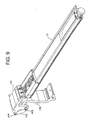
- the transparency lamp unit 13 is screwed on the fixture 141 at one end.
- the fixture 141 is attached to the fixture 142 on the flatbed carrier 11 through a pivot shaft 143.
- the fixture 141 and the transparency lamp unit 13 can be provided on the pivot shaft 143 so that they may pivotally move up and down, as shown in FIGS. 10 and 11B.
- FIG. 10 shows a state wherein the removable document table 15 has been removed, as described above.
- the reference numeral 103 indicates part of the housing 100.
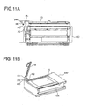
- FIG. 11A shows a situation wherein the cover 101 has been removed (in a side view)
- FIG. 11B also shows the state wherein the cover 101 has been removed (in a perspective view).
- the cover 101 is not provided within a path over which the fixture 142 moves in the sub scanning direction so that the cover 101 may not interfere with the movement.
- a cover glass for covering the irradiation surface of the transparency lamp unit 13 is provided so that it may be removed from the frame of the transparency lamp unit 13. This may allow the user to clean out dirt and dust inside the transparency lamp unit 13.
- the transparency lamp unit 13 is not built into the cover 101 but separately and independently provided to be exposed from the cover 101. This can allow the user to replace the transparency lamp unit 13 with ease when the amount of luminous from the transparency lamp unit 13 decreases due to aging.
- a spring 145 is provided between the pivot shaft 143 and a protrusion 144 formed on the fixture 141.
- the spring 145 is a coil spring, for example.
- the spring 145 is provided not only on the this side of the fixture 141 visible in FIG. 9 but on the opposite side thereof invisible in FIG. 9.
- the fixture 141 and the transparency lamp unit 13
- the long bar-like transparency lamp unit 13 can be firmly fixed in place without rattling even under acceleration.
- this can prevent the amount of luminous from the transparency lamp unit 13 from varying due to vibration of the transparency lamp unit 13 and displacement between their relative positions while the flatbed carrier 11 is moving.
- the transparency lamp unit 13 is fixed to the flatbed carrier 11 through a plurality of fixtures such as the fixture 141. Therefore, the transparency lamp unit 13 may be displaced from its proper attachment position as shown in FIGS. 4 and 5 due to various causes. These causes include, for example, replacement of the transparency lamp unit 13 by the user as described above and any shock or impact which may be given to the high-resolution scanner during transportation.
- the amount of luminous from the transparency lamp unit 13 may vary as described above.
- the control unit 16 detects the width of a ray bundle (the extent in the main scanning direction) from the transparency lamp unit 13 during a scanning operation before an image reading process starts and then causes the second driving unit 5 to drive the lens unit 4 in the main scanning direction based on the detected width.
- the optical axis can be positioned at the center of the ray bundle from the transparency lamp unit 13 to read an image more accurately (at a higher resolution).
- the platen glass provided as the document table 15 is removable, instead of the single platen glass, two platen glasses may be provided in a movable manner.
- one of the platen glasses which has a media placed thereon may be moved to the document table 15 for scanning the media, while the other may be moved outside the document table 15 to cause another media to be placed thereon during the scanning operation.
- This alternative configuration may increase the productivity in scanning.
- the present invention may apply to any scanner other than the high-resolution scanner described above.
- the present invention may also apply to any image reading apparatus which has lenses to optically read an image.
- the image reading apparatus of the present invention since the two lenses of low-resolution and high resolution can provide the first through third resolutions, the number of lenses can be smaller than that of the resolutions to be switched. This can reduce the price of the image reading apparatus satisfactorily. In particular, since the higher second and third resolutions can be achieved with the single lens, many different resolutions can be provided without the need for more expensive lenses. This can also reduce the price of the image reading apparatus more effectively.
- the optical unit can be moved in the main scanning direction, all image data can be acquired throughout the image reading region by moving the optical unit in the main scanning direction, even when the readable region is limited to a central portion in the main scanning direction as a result of resolution switching.
Landscapes
- Engineering & Computer Science (AREA)
- Multimedia (AREA)
- Signal Processing (AREA)
- Facsimile Scanning Arrangements (AREA)
- Image Input (AREA)
- Facsimile Heads (AREA)
- Optical Systems Of Projection Type Copiers (AREA)
Abstract
An image reading apparatus includes a lens unit (4) which
has a low-resolution lens (1), a high-resolution lens (2), and
a first driving unit (3) for driving them, and a second driving
unit (5) for driving the lens unit (4). At a first resolution,
the low-resolution lens (1) is placed on the optical axis at
a first location and the high-resolution lens (2) is placed off
the optical axis. At a second resolution higher than the first
resolution, the low-resolution lens (1) is placed off the optical
axis and the high-resolution lens (2) is placed on the optical
axis at a second location. At a third resolution higher than
the second resolution, the low-resolution lens (1) is placed
off the optical axis and the high-resolution lens (2) is placed
on the optical axis at a third location.
Description
This invention relates to an image reading apparatus, and
more particularly to an image reading apparatus which has two
lenses and read an image at any one of three resolutions which
are realized by moving the two lenses.
Various image reading apparatuses such as scanners include
a device with particularly high resolutions (hereinafter
referred to as a high-resolution scanner). Such a
high-resolution scanner can typically switch among several
resolutions, for example, 700 dpi, 2400 dpi, and 4000 dpi. Since
each of these three resolutions requires a lens for reading with
its resolution, three lenses are required in a case that the
resolutions are switched with such three levels, for example.
The price of a lens usually increases with resolution. In
addition, switching of resolutions results in reduction in its
readable region. The resultant readable region is limited to
a central portion in the width direction (main scanning
direction) of its document table (platen glass).
As described above, the high-resolution scanner requires
the same number of lenses as that of resolutions to be switched.
The lenses are very expensive and then the high-resolution
scanner is also expensive. In particular, this tendency may
become more pronounced in a scanner that provides higher
resolutions in multiple numbers.
As also described above, switching of resolutions will limit
the readable region to a central portion in the main scanning
direction. Thus, all image data cannot be acquired throughout
the whole range covered by the whole document table (that is,
the whole image reading region).
It is an object of the present invention to provide a
high-resolution image reading apparatus which can read an image
with fewer lenses and more resolutions.
An image reading apparatus of the present invention
comprises a lens unit having a low-resolution lens, a
high-resolution lens and a first driving unit to drive the lenses,
and a second driving unit to drive the lens unit. During a reading
operation at a first resolution, the first driving unit drives
the low-resolution lens and high-resolution lens and the second
driving unit drives the lens unit, whereby the low-resolution
lens is placed on the optical axis at a first location and the
high-resolution lens is placed off the optical axis. During
a reading operation at a second resolution, higher than the first
resolution, the first driving unit drives the low-resolution
lens and high-resolution lens and the second driving unit drives
the lens unit, whereby the low-resolution lens is placed off
the optical axis and the high-resolution lens is placed on the
optical axis at a second location. During a reading operation
at a third resolution, higher than the second resolution, the
first driving unit drives the low-resolution lens and
high-resolution lens and the second driving unit drives the lens
unit, whereby the low-resolution lens is placed off the optical
axis and the high-resolution lens is placed on the optical axis
at a third location.
According to the image reading apparatus of the present
invention, the two lenses of low-resolution and high resolution
can provide the first through third resolutions (that is, three
focuses). In particular, the single high-resolution lens can
provide the second and third resolutions. Therefore, the number
of lenses can be reduced to the number which is smaller than
that of the resolutions to be switched. This can reduce the
price of the image reading apparatus satisfactorily. In
addition, since the higher second and third resolutions can be
achieved with the single lens, many different resolutions can
be provided without the need for more expensive lenses. This
can also reduce the price of the image reading apparatus more
effectively.
FIGS. 1 through 3 show the configuration of an image reading
apparatus and schematically show the configuration of an image
reading apparatus according to the present invention. More
specifically, FIG. 1 is a block diagram of the image reading
apparatus, FIG. 2 is a schematic cross section of the image reading
apparatus, and FIG. 3 is a schematic plan view of the image reading
apparatus.
In this example, the image reading apparatus comprises a
flatbed-type high-resolution scanner (hereinafter referred to
as a high-resolution scanner) having a document table 15 on its
top. The document table 15 comprises a platen glass, for example.
Although not shown, the platen glass is provided to the frame
(housing 100 of the high-resolution scanner) in a removable
manner. This may allow the user to clean out dirt and dust inside
the housing 100 of the high-resolution scanner. Replacement
of the platen glass will be described later.
The high-resolution scanner comprises a control unit 16.
The control unit 16 controls first through fourth driving units
3, 5, 9, 12 as described below to move their driving targets
in a predetermined direction by a predetermined distance for
reading an image on a medium, respectively.
The high-resolution scanner comprises a lens unit 4. As
shown in FIG. 4 etc., the lens unit 4 comprises a low-resolution
lens 1, a high-resolution lens 2, and the first driving unit
3. The low-resolution lens 1 is used for a reading operation
with a resolution of 700 dpi, for example, at a first location,
as described below. The high-resolution lens 2 is used for a
reading operation with a resolution of 2400 dpi, for example,
at a second location and for a reading operation with a resolution
of 4000 dpi, for example, at a third location, as described below.
The lenses 1 and 2 move to provide the predetermined resolutions
as described below. The first driving unit 3 drives the lenses
1 and 2. The first driving unit 3 comprises a driving mechanism
including such as a motor, a rack, and gears (not shown). The
lenses 1 and 2 are moved into a predetermined direction by the
first driving unit 3.
The high-resolution scanner comprises an optical unit 8.
The lens unit 4 is part of the optical unit 8. More specifically,
the optical unit 8 has, as shown in FIG. 4A etc., the lens unit
4, the second driving unit 5 (not shown in FIG. 4A), a CCD sensor
unit 6, and at least first and second mirrors 7 (71, 72). The
lens unit 4 moves to provide the predetermined resolutions as
described below. The second driving unit 5 drives the lens unit
4. The lens unit 4 is moved into a predetermined direction by
the second driving unit 5. The CCD sensor unit 6 is a line sensor
which comprises a well-known charge-coupled device (CCD), reads
an image on a medium placed on the document table 15, and provides
output image data (electronic data).
The second driving unit 5 comprises a driving mechanism
including such as a motor, a rack, and gears (not shown). In
practice, the motor for the first driving unit 3 is also used
as the motor for the second driving unit 5.
The first mirror 71 turns the direction of the optical axis
(indicated by a dotted line in FIG. 2) in the optical unit 8.
The second mirror 72 turns the direction of the optical axis
in the flatbed carrier 11. More specifically, the first mirror
71 turns light from the second mirror 72 substantially by a right
angle to project it onto the CCD sensor unit 6, and the second
mirror 72 turns light from a light source substantially by a
right angle onto the first mirror 71. The light from the light
source is light which is supplied by a transparency lamp unit
13 and passes through a transparency-film document or light which
is supplied by a reflection lamp unit 10 and reflected by a
reflection-copy document. In the optical unit 8, as shown in
FIG. 4A etc., the optical axis is positioned so that it may connect
the CCD sensor unit 6 with the first mirror 71 and the first
mirror 71 with the second mirror 72 during a reading operation.
FIG. 6 shows a specific example of the configuration of
the optical unit 8 and the lens unit 4 and FIG. 7 shows the
configuration of the lens unit 4 in part.
In FIG. 6, the optical unit 8 is housed within the flatbed
carrier 11 as described below. The optical unit 8 is driven
by an X motor 91 (and a belt) in the main scanning direction
(X direction), along with the guide of two X shafts 92, 93. The
X motor 91 and the X shafts 92, 93 constitute the driving unit
9. The CCD sensor unit 6 is integrally provided to the optical
unit 8 and moves together therewith. The second mirror 72 is
fixed within the flatbed carrier 11 and is provided throughout
the whole range in the main scanning direction. Similarly, the
reflection lamp unit 10 is also fixed within the flatbed carrier
11 and is provided throughout the whole range in the main scanning
direction.
Thus, the optical unit 8 moves throughout the whole range
in the main scanning direction. As described above, during a
high-resolution reading operation, the readable region is
limited to a central portion in the main scanning direction.
Specifically, the readable region is physically substantially
equal to the CCD sensor unit 6 in a single reading line (a single
raster). Then, the control unit 16 moves the optical unit 8
throughout the whole range in the main scanning direction (from
the left end to the right end) during a high-resolution reading
operation (with one of the first through third resolutions).
This operation is repeated throughout the whole range in the
sub scanning direction. By this operation, high-resolution
image data can be acquired throughout the whole range of the
whole document table 15 (that is, the whole image reading region).
In FIG. 7, the lens unit 4 is integrally provided with the
low-resolution lens 1 and high-resolution lens 2. In the lens
unit 4, the low-resolution lens 1 is provided in the vertical
direction to be opposed to the CCD sensor unit 6, and the
high-resolution lens 2 is provided in the sub scanning direction
(Y direction). The first mirror 71 is integrally provided to
the optical unit 8 and moves together therewith. Therefore,
the first mirror 71 is provided not to cover through the whole
area in the main scanning direction but to cover an area
substantially corresponding to the width of the main scanning
direction of the CCD sensor unit 6 (or the lens unit 4). The
first driving unit 3 and the second driving unit 5 are integrally
provided to the optical unit 8 but they are not shown in the
figure. In FIG. 7, the lens unit 4 includes only two members
(portions) indicated by leader lines with the reference numeral
4 and the remaining members constitute the optical unit 8.
During a reading operation with the first resolution, the
control unit 16 causes the first driving unit 3 to drive the
low-resolution lens 1 and high-resolution lens 2 and causes the
second driving unit 5 to drive the lens unit 4. Resultant of
this operation, as shown in FIG. 4A, the low-resolution lens
1 is placed on the optical axis at the first location and the
high-resolution lens 2 is placed off the optical axis. The first
location is defined to be on the optical axis between the CCD
sensor unit 6 and the first mirror 71. This can allow the
low-resolution lens 1 to be adjusted to the focus position for
reading at 700 dpi, for example.
During a reading operation with the second resolution, the
control unit 16 causes the first driving unit 3 to drive the
low-resolution lens 1 and high-resolution lens 2, as shown in
FIG. 4B. The lenses 1 and 2 are integrally provided with each
other and are driven simultaneously. The driving is directed
to downward of the lens unit 4. This can allow the
high-resolution lens 2 to protrude from the lens unit 4 downward
so that the lens 2 is located on the optical axis between the
first and second mirrors 71 and 72. In addition, the control
unit 16 causes the second driving unit 5 to drive the lens unit
4. The driving is directed toward the second mirror 72. By
this operation, as shown in FIG. 5A, the low-resolution lens
1 is placed off the optical axis and the high-resolution lens
2 is placed on the optical axis at the second location. The
second location is defined to be on the optical axis between
the first mirror 71 and the second mirror 72 and closer to the
first mirror 71 than the third location. This can allow the
high-resolution lens 2 to be adjusted to the focus position for
reading at 2400 dpi, for example.
During a reading operation with the third resolution, the
control unit 16 causes the first driving unit 3 to drive the
low-resolution lens 1 and high-resolution lens 2 (from the
position as shown in FIG. 4A) and causes the second driving unit
5 to drive the lens unit 4 (from the position as shown in FIG.
5A). By this operation, as shown in FIG. 5B, the low-resolution
lens 1 is placed off the optical axis and the high-resolution
lens 2 is placed on the optical axis at the third location. The
third location is defined to be on the optical axis between the
first mirror 71 and the second mirror 72 and closer to the second
mirror 72 than the second location. That is, the third location
is the position at which longitudinal magnification is to be
used. This can allow the high-resolution lens 2 to be adjusted
to the focus position for reading at 4000 dpi, for example.
The first through third resolutions may be switched from
any one to another. Namely, the situations as shown in FIGS.
4A, 5A, and 5B may be mutually switchable. When switching, the
transition from the situation in FIG. 4A to that in FIG. 5A or
5B will be made through the situation in FIG. 4B.
The high-resolution scanner comprises the flatbed carrier
11. As shown in FIG. 6, the flatbed carrier 11 has a frame 111,
a front cover 112 and a cover 113. The optical unit 8 is housed
within the flatbed carrier 11 as part thereof. More specifically,
the flatbed carrier 11 includes the optical unit 8, the third
driving unit 9 and the reflection lamp unit 10. The optical
unit 8 moves in the main scanning direction (arrow A) mainly
during a high-resolution reading operation. The third driving
unit 9 drives the optical unit 8. The third driving unit 9
comprises a driving mechanism including such as a motor and a
guide (not shown). The optical unit 8 can be moved in the main
scanning direction by the third driving unit 9.
The reflection lamp unit 10 is used as a light source for
reading in a case that a medium on the document table 15 is a
reflection-copy document, and is provided on the whole range
throughout the main scanning direction as shown in FIG. 6. The
reflection lamp unit 10 is parallel to the transparency lamp
unit 13 and is fixed as part of the flatbed carrier 11 so that
it can move in the sub scanning direction as the flatbed carrier
11 moves.
As seen from FIGS. 4 and 6, the reflection lamp unit 10
is exposed without being covered by the cover 113 of the flatbed
carrier 11. This can allow the user to replace the reflection
lamp unit 10 with ease when the amount of luminous from the
reflection lamp unit 10 decreases due to aging.
The high-resolution scanner comprises the flatbed carrier
11 and the fourth driving unit 12 within the housing 100. The
flatbed carrier 11 is a carrier which moves in the sub scanning
direction (as indicated by the arrow B) during a reading operation.
The fourth driving unit 12 drives the flatbed carrier 11. The
fourth driving unit 12 comprises a driving mechanism including
such as a motor and a rail (not shown). The flatbed carrier
11 can be moved in the sub scanning direction by the fourth driving
unit 12.
The transparency lamp unit 13 is attached to the flatbed
carrier 11 with fixtures 14 (141, 142). The transparency lamp
unit 13 is used as a light source for reading in a case that
amediumon the document table 15 is a transparency-film document,
and is provided on the whole range throughout the main scanning
direction. The transparency lamp unit 13 is fixed to the flatbed
carrier 11 so that it can move in the sub scanning direction
together with the flatbed carrier 11 driven by the fourth driving
unit 12. This can prevent the amount of luminous from the
transparency lamp unit 13 from varying due to displacement
between their relative positions while the flatbed carrier 11
is moving. In a conventional system, the transparency lamp unit
13 is not attached to the flatbed carrier 11 and thus, the amount
of luminous may inevitably vary during the movement since they
are driven separately.
FIGS. 8 through 11 show specific configurations of the
flatbed carrier 11 and the transparency lamp unit 13.
In FIG. 8, the flatbed carrier 11 has a rectangular
parallelepipedic shape constructed by assembling the frame 111,
the front cover 112 and the cover 113 as described above. The
whole flatbed carrier 11 is driven by a carrier shaft 121 connected
to the motor (not shown) of the fourth driving unit 12 along
a rail 122 through the bearing 114. This can allow the flatbed
carrier 11 to move in the sub scanning direction. The carrier
shaft (unit) 121 and the rail 122 constitute the fourth driving
unit 12.
In FIG. 9, the transparency lamp unit 13 is screwed on the
fixture 141 at one end. As shown in FIG. 8, the fixture 141
is attached to the fixture 142 on the flatbed carrier 11 through
a pivot shaft 143. Thus, the fixture 141 and the transparency
lamp unit 13 can be provided on the pivot shaft 143 so that they
may pivotally move up and down, as shown in FIGS. 10 and 11B.
More specifically, as shown in FIG. 10, when the openable
cover 101 of the high-resolution scanner is opened, the
transparency lamp unit 13 movably attached on the undersurface
of the cover 101 pivots together with the cover 101. FIG. 10
shows a state wherein the removable document table 15 has been
removed, as described above. In FIG. 10, the reference numeral
103 indicates part of the housing 100. FIG. 11A shows a situation
wherein the cover 101 has been removed (in a side view) and FIG.
11B also shows the state wherein the cover 101 has been removed
(in a perspective view). As seen from these figures, the cover
101 is not provided within a path over which the fixture 142
moves in the sub scanning direction so that the cover 101 may
not interfere with the movement.
Although not shown, a cover glass for covering the
irradiation surface of the transparency lamp unit 13 is provided
so that it may be removed from the frame of the transparency
lamp unit 13. This may allow the user to clean out dirt and
dust inside the transparency lamp unit 13. As seen from FIG.
10 etc., the transparency lamp unit 13 is not built into the
cover 101 but separately and independently provided to be exposed
from the cover 101. This can allow the user to replace the
transparency lamp unit 13 with ease when the amount of luminous
from the transparency lamp unit 13 decreases due to aging.
A spring 145 is provided between the pivot shaft 143 and
a protrusion 144 formed on the fixture 141. The spring 145 is
a coil spring, for example. The spring 145 is provided not only
on the this side of the fixture 141 visible in FIG. 9 but on
the opposite side thereof invisible in FIG. 9. Thus, the fixture
141 (and the transparency lamp unit 13) can be strongly drawn
toward the fixture 142 or the pivot shaft 143. Consequently,
when the transparency lamp unit 13 moves in the sub scanning
direction together with the flatbed carrier 11, the long bar-like
transparency lamp unit 13 can be firmly fixed in place without
rattling even under acceleration. In addition, this can prevent
the amount of luminous from the transparency lamp unit 13 from
varying due to vibration of the transparency lamp unit 13 and
displacement between their relative positions while the flatbed
carrier 11 is moving.
In this way, the transparency lamp unit 13 is fixed to the
flatbed carrier 11 through a plurality of fixtures such as the
fixture 141. Therefore, the transparency lamp unit 13 may be
displaced from its proper attachment position as shown in FIGS.
4 and 5 due to various causes. These causes include, for example,
replacement of the transparency lamp unit 13 by the user as
described above and any shock or impact which may be given to
the high-resolution scanner during transportation. The amount
of luminous from the transparency lamp unit 13 may vary as
described above. To avoid such problem, the control unit 16
detects the width of a ray bundle (the extent in the main scanning
direction) from the transparency lamp unit 13 during a scanning
operation before an image reading process starts and then causes
the second driving unit 5 to drive the lens unit 4 in the main
scanning direction based on the detected width. Thus, the
optical axis can be positioned at the center of the ray bundle
from the transparency lamp unit 13 to read an image more accurately
(at a higher resolution).
While the present invention has been described above in
terms of the preferred embodiment, many different variations
may be possible within the scope of the present invention.
For example, since the platen glass provided as the document
table 15 is removable, instead of the single platen glass, two
platen glasses may be provided in a movable manner. In this
case, one of the platen glasses which has a media placed thereon
may be moved to the document table 15 for scanning the media,
while the other may be moved outside the document table 15 to
cause another media to be placed thereon during the scanning
operation. This alternative configuration may increase the
productivity in scanning.
The present invention may apply to any scanner other than
the high-resolution scanner described above. In addition to
these scanners, the present invention may also apply to any image
reading apparatus which has lenses to optically read an image.
As described above , according to the image reading apparatus
of the present invention, since the two lenses of low-resolution
and high resolution can provide the first through third
resolutions, the number of lenses can be smaller than that of
the resolutions to be switched. This can reduce the price of
the image reading apparatus satisfactorily. In particular,
since the higher second and third resolutions can be achieved
with the single lens, many different resolutions can be provided
without the need for more expensive lenses. This can also reduce
the price of the image reading apparatus more effectively.
Moreover, according to the image reading apparatus of the
present invention, since the optical unit can be moved in the
main scanning direction, all image data can be acquired
throughout the image reading region by moving the optical unit
in the main scanning direction, even when the readable region
is limited to a central portion in the main scanning direction
as a result of resolution switching.
Claims (12)
- An image reading apparatus comprising:wherein, during a reading operation at a first resolution, the first driving unit drives the low-resolution lens and high-resolution lens and the second driving unit drives the lens unit, whereby the low-resolution lens is placed on the optical axis at a first location and the high-resolution lens is placed off the optical axis,a lens unit having a low-resolution lens, a high-resolution lens and a first driving unit to drive the lenses; anda second driving unit to drive the lens unit,
wherein, during a reading operation at a second resolution, higher than the first resolution, the first driving unit drives the low-resolution lens and high-resolution lens and the second driving unit drives the lens unit, whereby the low-resolution lens is placed off the optical axis and the high-resolution lens is placed on the optical axis at a second location, and
wherein, during a reading operation at a third resolution, higher than the second resolution, the first driving unit drives the low-resolution lens and high-resolution lens and the second driving unit drives the lens unit, whereby the low-resolution lens is placed off the optical axis and the high-resolution lens is placed on the optical axis at a third location. - The image reading apparatus according to claim 1, wherein the first driving unit has a motor and the motor of the first driving unit is also used as the motor of the second driving unit.
- The image reading apparatus according to claim 1, further comprising:wherein location of the optical axis for reading is determined so as to connect the CCD sensor unit and the first mirror and connect the first mirror and the second mirror in the optical unit, andan optical unit having a CCD sensor unit and at least first and second mirrors, in addition to the lens unit and the second driving unit,
wherein the first location is defined to be on the optical axis between the CCD sensor unit and the first mirror, the second location is defined to be on the optical axis between the first mirror and the second mirror and closer to the first mirror than the third location, and the third location is defined to be on the optical axis between the first mirror and the second mirror and closer to the second mirror than the second location. - The image reading apparatus according to claim 3, wherein, in the lens unit, the low-resolution lens and the high-resolution lens are integrally provided to be driven simultaneously, the low-resolution lens is provided in the vertical direction to be opposed to the CCD sensor unit, and the high-resolution lens is provided in the sub scanning direction.
- The image reading apparatus according to claim 4,
wherein, during a reading operation at the first resolution, the high-resolution lens is placed above the optical axis between the first mirror and the second mirror to be placed off the optical axis, and
wherein, during a reading operation at the second or third resolution, the low-resolution lens is placed above the optical axis between the first mirror and the second mirror to be placed off the optical axis. - The image reading apparatus according to claim 5,
wherein the reading operations at the first, second, and third resolution are mutually switchable, and
wherein while switching from the reading operation at the first resolution to the reading operation at the second or third resolution, such a transitional situation occurs that the low-resolution lens is placed on the optical axis between the CCD sensor unit and the first mirror and the high-resolution lens is placed on the optical axis between the first mirror and the second mirror. - The image reading apparatus according to claim 1, further comprising:wherein the optical unit can be moved in main scanning direction.an optical unit having a CCD sensor unit and at least first and second mirrors, in addition to the lens unit and the second driving unit; anda third driving unit to drive the optical unit,
- The image reading apparatus according to claim 7, further comprising:wherein the flatbed carrier and the transparency lamp unit can be moved in sub scanning direction.a flatbed carrier having the optical unit and the third driving unit;a fourth driving unit to drive the flatbed carrier; anda transparency lamp unit being used as a light source to read a transparency-film document and being provided on the flatbed carrier,
- The image reading apparatus according to claim 8, further comprising:wherein the flatbed carrier further comprises its cover, anda reflection lamp unit being used as a light source to read a reflection-copy document and being provided on the flatbed carrier,
wherein the reflection lamp unit is not covered by the cover of the flatbed carrier to be exposed. - The image reading apparatus according to claim 8, further comprising:wherein the fixture further comprises:a fixture to attach the transparency lamp unit to the flatbed carrier,afirst fixture member having a protrusion and being attached to one end of the transparency lamp unit;a second fixture member being attached to the flatbed carrier, having a pivot shaft, and being attached to the first fixture rotatably through the pivot shaft; anda spring provided between the protrusion and the pivot shaft to draw each other.
- The image reading apparatus according to claim 10, further comprising:wherein the transparency lamp unit is movably attached on the undersurface of the cover and pivots together with the cover when the cover is opened or closed.a cover for the image reading apparatus and being provided in an openable manner,
- The image reading apparatus according to claim 8, wherein the optical axis of the transparency lamp unit is corrected by detecting the width of a ray bundle from the transparency lamp unit and causing the second driving unit to drive the lens unit based on the detected width.
Applications Claiming Priority (3)
| Application Number | Priority Date | Filing Date | Title |
|---|---|---|---|
| JP2001312951 | 2001-10-10 | ||
| JP2001312951A JP3974767B2 (en) | 2001-10-10 | 2001-10-10 | Image reading device |
| PCT/JP2002/010520 WO2003034706A1 (en) | 2001-10-10 | 2002-10-10 | Image reader |
Publications (2)
| Publication Number | Publication Date |
|---|---|
| EP1443745A1 true EP1443745A1 (en) | 2004-08-04 |
| EP1443745A4 EP1443745A4 (en) | 2006-06-07 |
Family
ID=19131516
Family Applications (1)
| Application Number | Title | Priority Date | Filing Date |
|---|---|---|---|
| EP02801525A Withdrawn EP1443745A4 (en) | 2001-10-10 | 2002-10-10 | IMAGE READER |
Country Status (4)
| Country | Link |
|---|---|
| US (1) | US7327499B2 (en) |
| EP (1) | EP1443745A4 (en) |
| JP (1) | JP3974767B2 (en) |
| WO (1) | WO2003034706A1 (en) |
Family Cites Families (21)
| Publication number | Priority date | Publication date | Assignee | Title |
|---|---|---|---|---|
| US6233063B1 (en) * | 1995-06-29 | 2001-05-15 | Agfa Corporation | Two lens converging device in a dual plane flat-bed scanning system |
| US5552939A (en) * | 1995-07-07 | 1996-09-03 | Umax Data Systems Inc. | Multi-lens changing mechanism for use in optical scanners |
| JP3439898B2 (en) * | 1995-12-05 | 2003-08-25 | 株式会社リコー | Image forming lens position adjusting device, image forming lens position adjusting method, and document reading device |
| US5907411A (en) * | 1996-07-17 | 1999-05-25 | Microtek International, Inc. | Multi-resolution transmissive and reflective optical scanner |
| JPH10119348A (en) * | 1996-10-22 | 1998-05-12 | Fuji Photo Film Co Ltd | Image recorder |
| JP3215064B2 (en) | 1997-03-14 | 2001-10-02 | 株式会社ピーエフユー | Control method of image reading device |
| US5883727A (en) * | 1997-05-06 | 1999-03-16 | Tsai; Shui Chuan | Multiple resolution image scanning module |
| AU685728B1 (en) | 1997-05-19 | 1998-01-22 | Umax Data Systems Inc. | Auto-focus mechanism |
| JPH118737A (en) * | 1997-06-17 | 1999-01-12 | Nikon Corp | Image input device, image input control device, and recording medium |
| JPH1117884A (en) | 1997-06-20 | 1999-01-22 | Pfu Ltd | Document reading device |
| US5995244A (en) * | 1997-07-23 | 1999-11-30 | Tsai; Shui Chuan | Multiple resolution page scanner |
| TW342114U (en) * | 1997-08-01 | 1998-10-01 | Mustek Systems Inc | A multiple resolution optic system (2) |
| US5903001A (en) * | 1997-10-21 | 1999-05-11 | Tsai; Shui Chuan | Multiple-resolution image scanning apparatus having plural imaging systems with a switching device |
| TW383132U (en) * | 1998-07-09 | 2000-02-21 | Microtek Int Inc | Optical path converter |
| US5969845A (en) * | 1998-09-16 | 1999-10-19 | Mustek Systems Inc. | Device and method for determining resolution of a multiple resolution scanner |
| US6339482B1 (en) * | 1998-09-30 | 2002-01-15 | Mustek System, Inc. | Control method for positioning multiple lens of scanner |
| DE19912691A1 (en) * | 1999-03-20 | 2000-09-21 | Heidelberger Druckmasch Ag | Device for scanning originals |
| JP2001169048A (en) * | 1999-12-09 | 2001-06-22 | Pfu Ltd | Image reading apparatus, control method therefor, and recording medium therefor |
| US6624914B1 (en) * | 2000-03-10 | 2003-09-23 | Hewlett-Packard Development Company, L.P. | Multiple resolution selectable lens scanning system and method |
| US6577410B1 (en) * | 2000-03-29 | 2003-06-10 | Shui-Chuan Tsai | Multiple resolution scanning device |
| US6667817B1 (en) * | 2000-08-31 | 2003-12-23 | Hewlett-Packard Development Company, L.P. | Multiple resolution scanner with improved lamp intensity monitoring capabilities |
-
2001
- 2001-10-10 JP JP2001312951A patent/JP3974767B2/en not_active Expired - Fee Related
-
2002
- 2002-10-10 EP EP02801525A patent/EP1443745A4/en not_active Withdrawn
- 2002-10-10 US US10/481,826 patent/US7327499B2/en not_active Expired - Fee Related
- 2002-10-10 WO PCT/JP2002/010520 patent/WO2003034706A1/en not_active Ceased
Also Published As
| Publication number | Publication date |
|---|---|
| JP3974767B2 (en) | 2007-09-12 |
| US7327499B2 (en) | 2008-02-05 |
| JP2003125161A (en) | 2003-04-25 |
| WO2003034706A1 (en) | 2003-04-24 |
| EP1443745A4 (en) | 2006-06-07 |
| US20040165286A1 (en) | 2004-08-26 |
Similar Documents
| Publication | Publication Date | Title |
|---|---|---|
| US5610731A (en) | Image scanner having contact-type image sensor movable under automatic document feeder | |
| EP1309169B1 (en) | Image reading apparatus | |
| US6424433B1 (en) | Original reader | |
| US6473206B1 (en) | Image scanner | |
| EP0901272A2 (en) | Single lamp illumination system for a dual plane flat-bed scanner | |
| JP4979452B2 (en) | Image reading device | |
| US20020191994A1 (en) | Book scanning device | |
| EP0785664B1 (en) | Apparatus and method for optically scanning a document | |
| US7327499B2 (en) | Image reading apparatus | |
| JPH11289430A (en) | Image reading device and image forming device | |
| US6762861B2 (en) | Scanner with a movable mirror set in the scanning module for increasing the resolution of scanned images | |
| US20010013957A1 (en) | High resolution scanner | |
| US5959745A (en) | Transmission mechanism for an image information reading apparatus | |
| JP5118083B2 (en) | Dual mirror lighting system for book copier | |
| JPH0723180A (en) | Image reader | |
| GB2325532A (en) | Optical scanner | |
| US4607951A (en) | Compensating platen for dual mode image input terminals | |
| US7344075B2 (en) | Scanning apparatus and guiding mechanism thereof | |
| KR100389871B1 (en) | Apparatus for moving scanning carriage in image read-out device | |
| JPH05153333A (en) | Picture reader | |
| JPH05136958A (en) | Reflective transparent original reader | |
| JPH06225085A (en) | Optical unit of image reading device | |
| JPH062751A (en) | Shifting mechanism and vibration control member therefor | |
| JPH03195172A (en) | Picture reader | |
| JPH1175011A (en) | Picture reader |
Legal Events
| Date | Code | Title | Description |
|---|---|---|---|
| PUAI | Public reference made under article 153(3) epc to a published international application that has entered the european phase |
Free format text: ORIGINAL CODE: 0009012 |
|
| 17P | Request for examination filed |
Effective date: 20040505 |
|
| AK | Designated contracting states |
Kind code of ref document: A1 Designated state(s): DE FR GB |
|
| AX | Request for extension of the european patent |
Extension state: AL LT LV MK RO SI |
|
| A4 | Supplementary search report drawn up and despatched |
Effective date: 20060427 |
|
| 17Q | First examination report despatched |
Effective date: 20060925 |
|
| STAA | Information on the status of an ep patent application or granted ep patent |
Free format text: STATUS: THE APPLICATION IS DEEMED TO BE WITHDRAWN |
|
| 18D | Application deemed to be withdrawn |
Effective date: 20090616 |