EP1443636A1 - Verfahren zur Bestimmung der Drehzahl eines Motors - Google Patents
Verfahren zur Bestimmung der Drehzahl eines Motors Download PDFInfo
- Publication number
- EP1443636A1 EP1443636A1 EP03002211A EP03002211A EP1443636A1 EP 1443636 A1 EP1443636 A1 EP 1443636A1 EP 03002211 A EP03002211 A EP 03002211A EP 03002211 A EP03002211 A EP 03002211A EP 1443636 A1 EP1443636 A1 EP 1443636A1
- Authority
- EP
- European Patent Office
- Prior art keywords
- motor
- signals
- microphone
- sound waves
- microphones
- Prior art date
- Legal status (The legal status is an assumption and is not a legal conclusion. Google has not performed a legal analysis and makes no representation as to the accuracy of the status listed.)
- Granted
Links
Images
Classifications
-
- G—PHYSICS
- G01—MEASURING; TESTING
- G01P—MEASURING LINEAR OR ANGULAR SPEED, ACCELERATION, DECELERATION, OR SHOCK; INDICATING PRESENCE, ABSENCE, OR DIRECTION, OF MOVEMENT
- G01P3/00—Measuring linear or angular speed; Measuring differences of linear or angular speeds
- G01P3/42—Devices characterised by the use of electric or magnetic means
- G01P3/44—Devices characterised by the use of electric or magnetic means for measuring angular speed
Definitions
- the invention relates to a method for Determination of the speed of an engine at which that of a rotating engine emitted noise is used as a measure of the speed. Furthermore, the Invention also a device for performing the inventive Process.
- FIGS. 8A and 8B of this document show in one schematic representation of a motor 601 and one arranged on the motor Microphone 176, for example using an adhesive on the motor housing is attached.
- a noise in the present case a hum, which is a measure of the Represents engine speed.
- the hum detected by the microphone turns into a PWM signal converted, the pulse width depending on the particular Engine speed varies and this relationship to determine the Speed is evaluated accordingly.
- the invention is therefore based on the object of a method of the beginning to propose the type mentioned, which while avoiding the disadvantages of State of the art, simple and accurate and reliable Speed determination enables.
- the invention takes advantage of the fact that one deals with the engine rotating part, e.g. B. arranged for cooling the motor on the motor shaft Fan wheel with rotating motor causes sound waves from at least one in the Microphone located near the rotating part of the motor can be detected.
- the frequency detected here is proportional to the speed of the motor, see above that the engine speed is accurate based on the detected frequency of the sound waves can be determined.
- the engine speed is preferably based on the frequency and the number of fan blades of the fan wheel.
- fan wheel rotating part e.g. B. a grooved motor armature or one on the Motor shaft arranged perforated disc, which is in a known relationship to the rotating motor stands and causes a detectable noise to determine the Engine speed can be used.
- the noises coming from the rotating part can be very quietly and also undesirably superimposed by extraneous noises or ambient noises, whereby the accuracy is impaired.
- two phase-shifted signals are then obtained from the noise generated by the rotating part of the motor by means of the two microphones, whereas the ambient or external noises, however, generate signals in phase. This applies if the distance between the microphones is chosen to be smaller than the wavelength of the frequencies to be recorded.
- the use of two microphones also has the advantage that, for. B. from the direction of the phase shift of the microphone signals, the direction of rotation of the motor can be determined.
- the sensitivity of the microphones can also be reduced due to the Ambient conditions fluctuate, so that there are differences in do not have the signals completely eliminated by a single calibration.
- a Amplitude or signal level control proposed that the of the microphones obtained signals at a constant same level before the signals be subtracted from each other.
- Such an amplitude control also has the advantage that the circuit for evaluating the useful signal can be optimally controlled can. For example, inexpensive components in the form of Operational amplifiers are used.
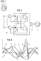
- Figure 1 shows a schematic representation of a preferred embodiment the invention with a fan wheel and two microphones, which are used to determine the Speed of a motor can be used.
- FIG. 2 shows a preferred one in a simplified block diagram Embodiment of a circuit arrangement for performing the inventive method.
- Figure 3 shows an example of the signal waveforms in a diagram inventive method.
- FIG. 1 shows, for example, a fan wheel 8, which is not used for cooling one here engine shown is provided.
- the fan wheel 8 is usually on the Motor shaft of the motor arranged and has a plurality of fan blades 9, in In this case, eight fan blades for cooling the motor. With rotating Motor generates the fan wheel sound waves, the frequency of which is detected Sound waves is proportional to the speed.
- sound waves generated are by one preferably of two microphones 1 arranged in the vicinity of the fan wheel recorded, from the detected frequency and the known number of Fan blades the engine speed can be determined. For example, the engine speed at a detected frequency of 400 Hz and at eight Fan blades at 3000 revolutions / minute.
- the microphones are preferably turned on attached a grille of the fan wheel 8, not shown here.
- Figure 2 shows an embodiment of the invention with two microphones 1, as in Figure 1 shown, are positioned close to each other.
- the distance of the microphones should, so that an effective suppression of external noise or Ambient noise is guaranteed to be as close as possible in any case smaller be chosen as the wavelength of the frequencies to be detected.
- the one from the Signals obtained from the two microphones 1 are fed to a circuit 10.
- the Output signals of the microphones are two-channel from the circuit 10 processed and z. B. the amplifiers 2 and the rectifiers 3, supplied.
- the amplified and rectified signals are then fed to the controllers 5 and compared with a reference signal 4, which is the same for both controllers, the Manipulated variable of the controller 5 controls the corresponding amplifier 2. Thereby you get two signals with the same amplitude.
- Figure 3 shows the z. B. obtained by the inventive circuit arrangement according to FIG. 2 waveforms, which are shown in a diagram.
- the signals A and B received by the microphones 1 are out of phase with one another owing to the spatially offset arrangement of the microphones 1.
- signals A and B have the same amplitude and the same signal level.
- the signal C represents z. B. represents a stochastic interference signal, which is superimposed, for example, on the signals A and B, as shown in the disturbed signal profiles A 'and B'.
- the useful signal D obtained from the subtraction of the signal profiles A 'and B' is then used to determine the speed of the engine.
- the method according to the invention also enables the direction of rotation of the motor to be determined, which can be determined in a simple manner from the direction of the phase shift.
- the direction of rotation can be determined from the phase shift of the amplified or unamplified microphone signals or from the phase shift of the useful signal obtained from the subtraction, based on one of the two of the microphone signals.
Landscapes
- Physics & Mathematics (AREA)
- General Physics & Mathematics (AREA)
- Measurement Of Mechanical Vibrations Or Ultrasonic Waves (AREA)
- Control Of Electric Motors In General (AREA)
- Soundproofing, Sound Blocking, And Sound Damping (AREA)
Abstract
Description
Um dies zu vermeiden, wird gemäss einer Weiterbildung der Erfindung vorgeschlagen, zwei dicht zueinander positionierte Mikrofone vorzusehen, die beispielsweise am Abdeckgitter des Lüfters befestigt sind. Dadurch werden aus dem von dem drehenden Teil des Motors erzeugten Geräusch dann mittels der beiden Mikrofone zwei phasenverschobene Signale erhalten, wohingegen die Umgebungs- bzw. Fremdgeräusche jedoch phasengleiche Signale erzeugen. Dies gilt dann, wenn bei der Positionierung der Abstand der Mikrofone zueinander kleiner als die Wellenlänge der zu erfassenden Frequenzen gewählt wird. Werden die von den beiden Mikrofonen erhaltenen phasenverschobenen Signale subtrahiert, so löschen sich dabei die von den Fremdgeräuschen herrührenden Störsignale aus und es bleibt nur das Nutzsignal übrig. Dieses wird dann zur Bestimmung der Drehzahl verwendet. Weiterhin hat die Verwendung von zwei Mikrofonen jedoch auch den Vorteil, dass z. B. aus der Richtung der Phasenverschiebung der Mikrofonsignale auch die Drehrichtung des Motors bestimmt werden kann.
Beispielsweise kann die Drehrichtung aus der Phasenverschiebung der verstärkten oder unverstärkten Mikrofonsignale beziehungsweise aus der Phasenverschiebung des aus der Subtraktion erhaltenes Nutzsignals bezogen auf eines der beiden der Mikrofonsignale ermittelt werden.
Claims (14)
- Verfahren zur Bestimmung der Drehzahl eines Motors, bei dem das von einem rotierenden Motor abgegebene Geräusch als Mass für die Drehzahl verwendet wird, dadurch gekennzeichnet, dass die von einem drehenden Teil des rotierenden Motors erzeugten Schallwellen von wenigstens einem Mikrofon erfasst und das anhand der Frequenz der detektierten Schallwellen die Motordrehzahl bestimmt wird.
- Verfahren nach Anspruch 1, dadurch gekennzeichnet, dass die Motordrehzahl anhand der detektierten Frequenz der von einem Lüfterrad des Motors erzeugten Schallwellen und der Anzahl der Lüfterschaufeln des Lüfterrades ermittelt wird.
- Verfahren nach Anspruch 1 oder 2, dadurch gekennzeichnet, dass ein weiteres Mikrofon zur Erfassung der erzeugten Schallwellen vorgesehen ist, wobei das von dem zweiten Mikrofon erhaltene Signal in Bezug auf das vom ersten Mikrofon erhaltene Signal phasenverschoben zu diesem ist und dass die beiden zueinander phasenverschobenen Mikrofonsignale voneinander subtrahiert werden, wobei das aus der Subtraktion erhaltene Nutzsignal zur Bestimmung der Drehzahl des Motors verwendet wird.
- Verfahren nach Anspruch 3, dadurch gekennzeichnet, dass die von den Mikrofonen erhaltenen Signale verstärkt und/oder in der Bandbreite begrenzt werden, bevor diese voneinander subtrahiert werden.
- Verfahren nach Anspruch 3 oder 4, dadurch gekennzeichnet, dass die Signale der Mikrofone auf gleichen Pegel gebracht werden und diese Signale voneinander subtrahiert werden.
- Verfahren nach Anspruch 3, dadurch gekennzeichnet, dass aus der Richtung der Phasenverschiebung die Drehrichtung des Motors bestimmt wird.
- Verfahren anch Anspruch 6, dadurch gekennzeichnet, dass die Drehrichtung aus der Phasenverschiebung der verstärkten oder unverstärkten Mikrofonsignale ermittelt wird.
- Verfahren anch Anspruch 6, dadurch gekennzeichnet, dass die Drehrichtung aus der Phasenverschiebung des aus der Subtraktion erhaltenen Nutzsignals bezogen auf eines der beiden Mikrofonsignale ermittelt wird.
- Vorrichtung zur Durchführung des Verfahrens nach Anspruch 1, dadurch gekennzeichnet, dass die von einem rotierenden Teil (8) eines Motors erzeugten Schallwellen von wenigstens einem in der Nähe des rotierenden Teils (8) des Motors angeordneten Mikrofones (1) erfasst und dass anhand der Frequenz der detektierten Schallwellen die Bestimmung der Drehzahl des Motors erfolgt.
- Vorrichtung nach Anspruch 9, dadurch gekennzeichnet, dass das rotierende Teil (8) des Motors ein zur Kühlung des Motors vorgesehenes Lüfterrad (8) mit Lüfterschaufeln (9) ist.
- Vorrichtung nach Anspruch 9 und 10, dadurch gekennzeichnet, dass ein zweites Mikrofon (1) zur Erfassung der von dem rotierenden Teil (8) erzeugten Schallwellen in einem Abstand der kleiner der Wellenlänge der zur detektierenden Frequenz der Schallwellen ist zu dem ersten Mikrofon (1) angeordnet ist, wodurch die von den beiden Mikrofonen (1) erhaltenen Signale phasenverschoben zueinander sind und dass diese phasenverschobenen Signale mittels eines Subtrahierers (6) voneinander subtrahiert werden.
- Vorrichtung nach Anspruch 11, dadurch gekennzeichnet, dass Verstärker (2) zur Verstärkung der von den Mikrofonen (1) erhaltenen Signale und/oder Gleichrichter (3) zur Gleichrichtung der Mikrofonsignale vorgesehen sind, wobei die verstärkten und/oder gleichgerichteten Mikrofonsignale voneinander subtrahiert werden.
- Vorrichtung nach Anspruch 12, dadurch gekennzeichnet, dass die verstärkten und/oder gleichgerichteten Mikrofonsignale Reglern (5) zugeführt werden und mit einem Referenzsignal (4) verglichen werden, dass für beide Regler (5) gleich ist, wobei die Regler (5) die Verstärker (2) derart steuern, dass die Mikrofonsignale den gleichen Signalpegel aufweisen und diese Signale mittels des Subtrahierers (6) voneinander subtrahiert werden.
- Vorrichtung nach Anspruch 11, dadurch gekennzeichnet, dass das von dem Subtrahierer (6) erhaltene Signal durch einen nachgeschalteten Filter (7) in der Bandbreite begrenzt wird.
Priority Applications (3)
| Application Number | Priority Date | Filing Date | Title |
|---|---|---|---|
| AT03002211T ATE330356T1 (de) | 2003-01-31 | 2003-01-31 | Verfahren zur bestimmung der drehzahl eines motors |
| EP03002211A EP1443636B1 (de) | 2003-01-31 | 2003-01-31 | Verfahren zur Bestimmung der Drehzahl eines Motors |
| DE50303809T DE50303809D1 (de) | 2003-01-31 | 2003-01-31 | Verfahren zur Bestimmung der Drehzahl eines Motors |
Applications Claiming Priority (1)
| Application Number | Priority Date | Filing Date | Title |
|---|---|---|---|
| EP03002211A EP1443636B1 (de) | 2003-01-31 | 2003-01-31 | Verfahren zur Bestimmung der Drehzahl eines Motors |
Publications (2)
| Publication Number | Publication Date |
|---|---|
| EP1443636A1 true EP1443636A1 (de) | 2004-08-04 |
| EP1443636B1 EP1443636B1 (de) | 2006-06-14 |
Family
ID=32605291
Family Applications (1)
| Application Number | Title | Priority Date | Filing Date |
|---|---|---|---|
| EP03002211A Expired - Lifetime EP1443636B1 (de) | 2003-01-31 | 2003-01-31 | Verfahren zur Bestimmung der Drehzahl eines Motors |
Country Status (3)
| Country | Link |
|---|---|
| EP (1) | EP1443636B1 (de) |
| AT (1) | ATE330356T1 (de) |
| DE (1) | DE50303809D1 (de) |
Cited By (3)
| Publication number | Priority date | Publication date | Assignee | Title |
|---|---|---|---|---|
| DE102015114668A1 (de) * | 2015-09-02 | 2017-03-02 | Alfred Kärcher Gmbh & Co. Kg | Saugvorrichtung und Verfahren zum Betreiben einer Saugvorrichtung |
| CN112146958A (zh) * | 2020-09-27 | 2020-12-29 | 中国家用电器研究院 | 一种噪声声功率级标准样品及其制备方法 |
| CN115453138A (zh) * | 2022-08-08 | 2022-12-09 | 明阳智慧能源集团股份公司 | 一种风力发电机组叶轮转速测量方法、系统、设备及介质 |
Citations (2)
| Publication number | Priority date | Publication date | Assignee | Title |
|---|---|---|---|---|
| US4479115A (en) * | 1982-08-06 | 1984-10-23 | At&T Bell Laboratories | Fan speed and/or fan failure detector |
| US5953490A (en) * | 1993-08-20 | 1999-09-14 | Woel Elektronik Hb | Circuit for speed control for a one-phase or three-phase motor |
-
2003
- 2003-01-31 DE DE50303809T patent/DE50303809D1/de not_active Expired - Lifetime
- 2003-01-31 EP EP03002211A patent/EP1443636B1/de not_active Expired - Lifetime
- 2003-01-31 AT AT03002211T patent/ATE330356T1/de not_active IP Right Cessation
Patent Citations (2)
| Publication number | Priority date | Publication date | Assignee | Title |
|---|---|---|---|---|
| US4479115A (en) * | 1982-08-06 | 1984-10-23 | At&T Bell Laboratories | Fan speed and/or fan failure detector |
| US5953490A (en) * | 1993-08-20 | 1999-09-14 | Woel Elektronik Hb | Circuit for speed control for a one-phase or three-phase motor |
Cited By (3)
| Publication number | Priority date | Publication date | Assignee | Title |
|---|---|---|---|---|
| DE102015114668A1 (de) * | 2015-09-02 | 2017-03-02 | Alfred Kärcher Gmbh & Co. Kg | Saugvorrichtung und Verfahren zum Betreiben einer Saugvorrichtung |
| CN112146958A (zh) * | 2020-09-27 | 2020-12-29 | 中国家用电器研究院 | 一种噪声声功率级标准样品及其制备方法 |
| CN115453138A (zh) * | 2022-08-08 | 2022-12-09 | 明阳智慧能源集团股份公司 | 一种风力发电机组叶轮转速测量方法、系统、设备及介质 |
Also Published As
| Publication number | Publication date |
|---|---|
| EP1443636B1 (de) | 2006-06-14 |
| ATE330356T1 (de) | 2006-07-15 |
| DE50303809D1 (de) | 2006-07-27 |
Similar Documents
| Publication | Publication Date | Title |
|---|---|---|
| DE10085353B4 (de) | Servosteuervorrichtung | |
| DE19851942B4 (de) | Drehzahl-, Richtungs- und Beschleunigungssensor für eine rotierende Welle | |
| DE102022202092A1 (de) | Verfahren zur Zustandsüberwachung für schallemittierende Maschinen | |
| DE69517075T2 (de) | Gerät zur Diagnose von Schall- und Schwingungsquellen | |
| DE69424587T2 (de) | Vorrichtung zur aktiven Geräuschdämpfung mit adaptiver Steuerung | |
| DE102018201168A1 (de) | Verfahren und Vorrichtung zum Verarbeiten von Sensorsignalen | |
| DE102008044088A1 (de) | Verfahren zur dynamischen Ermittlung des Rauschlevels | |
| DE69818380T2 (de) | Verfahren zur Überwachung eines mit Beschleunigungssensoren versehenen Planetengetriebes in einem Fortbewegungsmittel, insbesondere in einem Helikopter | |
| DE112022006364B4 (de) | Störungsentfernungseinrichtung und -Verfahren | |
| EP1409965A1 (de) | Verfahren und vorrichtung zur korrektur des dynamikfehlers eines sensors | |
| DE69011566T2 (de) | Akustisches Detektionsgerät. | |
| EP1443636B1 (de) | Verfahren zur Bestimmung der Drehzahl eines Motors | |
| DE102005040192A1 (de) | Verfahren und Vorrichtung zur Erkennung von Quietschgeräuschen | |
| DE10394087T5 (de) | Motorsteuereinrichtung | |
| DE10236735B4 (de) | Verfahren zur Generierung von zum Fahrbetrieb schädigungsäquivalenten Rauschprofilen zur Vibrationsprüfung von Fahrzeugkomponenten | |
| EP1858289A1 (de) | Hörvorrichtung mit Rückkopplungsdetektion und entsprechendes Verfahren | |
| DE3026232C2 (de) | Verfahren und Vorrichtung zur Größenanzeige einer Unwucht beim Auswuchten von Rotoren | |
| DE2748288C2 (de) | ||
| EP0733293B2 (de) | Rauschpegelbestimmungsverfahren und rauschpegeldetektor | |
| EP1401243B1 (de) | Verfahren zum Optimieren eines Audiosignals | |
| DE19518409C1 (de) | Verfahren zur akustischen Fehlererkennung | |
| WO2019092240A2 (de) | Vorrichtung und verfahren zum rotationssynchronen überwachen eines rotierenden elements | |
| EP0308526A1 (de) | Geräuschbeurteilung von Fahrzeugpumpen | |
| DE10010037B4 (de) | Verfahren zur Rekonstruktion tieffrequenter Sprachanteile aus mittelhohen Frequenzanteilen | |
| DE19954066C1 (de) | Verfahren zur Ordnungs-Analyse von Schwingungen eines rotierenden Teiles, insbesondere einer Maschine |
Legal Events
| Date | Code | Title | Description |
|---|---|---|---|
| PUAI | Public reference made under article 153(3) epc to a published international application that has entered the european phase |
Free format text: ORIGINAL CODE: 0009012 |
|
| AK | Designated contracting states |
Kind code of ref document: A1 Designated state(s): AT BE BG CH CY CZ DE DK EE ES FI FR GB GR HU IE IT LI LU MC NL PT SE SI SK TR |
|
| AX | Request for extension of the european patent |
Extension state: AL LT LV MK RO |
|
| 17P | Request for examination filed |
Effective date: 20041206 |
|
| AKX | Designation fees paid |
Designated state(s): AT BE BG CH CY CZ DE DK EE ES FI FR GB GR HU IE IT LI LU MC NL PT SE SI SK TR |
|
| 17Q | First examination report despatched |
Effective date: 20050415 |
|
| RAP1 | Party data changed (applicant data changed or rights of an application transferred) |
Owner name: SIEMENS SCHWEIZ AG |
|
| GRAP | Despatch of communication of intention to grant a patent |
Free format text: ORIGINAL CODE: EPIDOSNIGR1 |
|
| GRAS | Grant fee paid |
Free format text: ORIGINAL CODE: EPIDOSNIGR3 |
|
| GRAA | (expected) grant |
Free format text: ORIGINAL CODE: 0009210 |
|
| AK | Designated contracting states |
Kind code of ref document: B1 Designated state(s): AT BE BG CH CY CZ DE DK EE ES FI FR GB GR HU IE IT LI LU MC NL PT SE SI SK TR |
|
| PG25 | Lapsed in a contracting state [announced via postgrant information from national office to epo] |
Ref country code: IT Free format text: LAPSE BECAUSE OF FAILURE TO SUBMIT A TRANSLATION OF THE DESCRIPTION OR TO PAY THE FEE WITHIN THE PRESCRIBED TIME-LIMIT;WARNING: LAPSES OF ITALIAN PATENTS WITH EFFECTIVE DATE BEFORE 2007 MAY HAVE OCCURRED AT ANY TIME BEFORE 2007. THE CORRECT EFFECTIVE DATE MAY BE DIFFERENT FROM THE ONE RECORDED. Effective date: 20060614 Ref country code: IE Free format text: LAPSE BECAUSE OF FAILURE TO SUBMIT A TRANSLATION OF THE DESCRIPTION OR TO PAY THE FEE WITHIN THE PRESCRIBED TIME-LIMIT Effective date: 20060614 Ref country code: FI Free format text: LAPSE BECAUSE OF FAILURE TO SUBMIT A TRANSLATION OF THE DESCRIPTION OR TO PAY THE FEE WITHIN THE PRESCRIBED TIME-LIMIT Effective date: 20060614 Ref country code: CZ Free format text: LAPSE BECAUSE OF FAILURE TO SUBMIT A TRANSLATION OF THE DESCRIPTION OR TO PAY THE FEE WITHIN THE PRESCRIBED TIME-LIMIT Effective date: 20060614 Ref country code: GB Free format text: LAPSE BECAUSE OF FAILURE TO SUBMIT A TRANSLATION OF THE DESCRIPTION OR TO PAY THE FEE WITHIN THE PRESCRIBED TIME-LIMIT Effective date: 20060614 Ref country code: SI Free format text: LAPSE BECAUSE OF FAILURE TO SUBMIT A TRANSLATION OF THE DESCRIPTION OR TO PAY THE FEE WITHIN THE PRESCRIBED TIME-LIMIT Effective date: 20060614 Ref country code: SK Free format text: LAPSE BECAUSE OF FAILURE TO SUBMIT A TRANSLATION OF THE DESCRIPTION OR TO PAY THE FEE WITHIN THE PRESCRIBED TIME-LIMIT Effective date: 20060614 Ref country code: NL Free format text: LAPSE BECAUSE OF FAILURE TO SUBMIT A TRANSLATION OF THE DESCRIPTION OR TO PAY THE FEE WITHIN THE PRESCRIBED TIME-LIMIT Effective date: 20060614 |
|
| REG | Reference to a national code |
Ref country code: GB Ref legal event code: FG4D Free format text: NOT ENGLISH |
|
| REG | Reference to a national code |
Ref country code: CH Ref legal event code: EP |
|
| REG | Reference to a national code |
Ref country code: IE Ref legal event code: FG4D Free format text: LANGUAGE OF EP DOCUMENT: GERMAN |
|
| REF | Corresponds to: |
Ref document number: 50303809 Country of ref document: DE Date of ref document: 20060727 Kind code of ref document: P |
|
| PG25 | Lapsed in a contracting state [announced via postgrant information from national office to epo] |
Ref country code: SE Free format text: LAPSE BECAUSE OF FAILURE TO SUBMIT A TRANSLATION OF THE DESCRIPTION OR TO PAY THE FEE WITHIN THE PRESCRIBED TIME-LIMIT Effective date: 20060914 Ref country code: DK Free format text: LAPSE BECAUSE OF FAILURE TO SUBMIT A TRANSLATION OF THE DESCRIPTION OR TO PAY THE FEE WITHIN THE PRESCRIBED TIME-LIMIT Effective date: 20060914 |
|
| PG25 | Lapsed in a contracting state [announced via postgrant information from national office to epo] |
Ref country code: ES Free format text: LAPSE BECAUSE OF FAILURE TO SUBMIT A TRANSLATION OF THE DESCRIPTION OR TO PAY THE FEE WITHIN THE PRESCRIBED TIME-LIMIT Effective date: 20060925 |
|
| PG25 | Lapsed in a contracting state [announced via postgrant information from national office to epo] |
Ref country code: PT Free format text: LAPSE BECAUSE OF FAILURE TO SUBMIT A TRANSLATION OF THE DESCRIPTION OR TO PAY THE FEE WITHIN THE PRESCRIBED TIME-LIMIT Effective date: 20061114 |
|
| NLV1 | Nl: lapsed or annulled due to failure to fulfill the requirements of art. 29p and 29m of the patents act | ||
| GBV | Gb: ep patent (uk) treated as always having been void in accordance with gb section 77(7)/1977 [no translation filed] |
Effective date: 20060614 |
|
| PG25 | Lapsed in a contracting state [announced via postgrant information from national office to epo] |
Ref country code: LI Free format text: LAPSE BECAUSE OF NON-PAYMENT OF DUE FEES Effective date: 20070131 Ref country code: MC Free format text: LAPSE BECAUSE OF NON-PAYMENT OF DUE FEES Effective date: 20070131 Ref country code: CH Free format text: LAPSE BECAUSE OF NON-PAYMENT OF DUE FEES Effective date: 20070131 |
|
| REG | Reference to a national code |
Ref country code: IE Ref legal event code: FD4D |
|
| PLBE | No opposition filed within time limit |
Free format text: ORIGINAL CODE: 0009261 |
|
| STAA | Information on the status of an ep patent application or granted ep patent |
Free format text: STATUS: NO OPPOSITION FILED WITHIN TIME LIMIT |
|
| EN | Fr: translation not filed | ||
| 26N | No opposition filed |
Effective date: 20070315 |
|
| REG | Reference to a national code |
Ref country code: CH Ref legal event code: PL |
|
| BERE | Be: lapsed |
Owner name: SIEMENS SCHWEIZ A.G. Effective date: 20070131 |
|
| PG25 | Lapsed in a contracting state [announced via postgrant information from national office to epo] |
Ref country code: BE Free format text: LAPSE BECAUSE OF NON-PAYMENT OF DUE FEES Effective date: 20070131 |
|
| PG25 | Lapsed in a contracting state [announced via postgrant information from national office to epo] |
Ref country code: FR Free format text: LAPSE BECAUSE OF FAILURE TO SUBMIT A TRANSLATION OF THE DESCRIPTION OR TO PAY THE FEE WITHIN THE PRESCRIBED TIME-LIMIT Effective date: 20070309 Ref country code: GR Free format text: LAPSE BECAUSE OF FAILURE TO SUBMIT A TRANSLATION OF THE DESCRIPTION OR TO PAY THE FEE WITHIN THE PRESCRIBED TIME-LIMIT Effective date: 20060915 |
|
| PG25 | Lapsed in a contracting state [announced via postgrant information from national office to epo] |
Ref country code: AT Free format text: LAPSE BECAUSE OF NON-PAYMENT OF DUE FEES Effective date: 20070131 Ref country code: BG Free format text: LAPSE BECAUSE OF FAILURE TO SUBMIT A TRANSLATION OF THE DESCRIPTION OR TO PAY THE FEE WITHIN THE PRESCRIBED TIME-LIMIT Effective date: 20060914 |
|
| PG25 | Lapsed in a contracting state [announced via postgrant information from national office to epo] |
Ref country code: EE Free format text: LAPSE BECAUSE OF FAILURE TO SUBMIT A TRANSLATION OF THE DESCRIPTION OR TO PAY THE FEE WITHIN THE PRESCRIBED TIME-LIMIT Effective date: 20060614 |
|
| PG25 | Lapsed in a contracting state [announced via postgrant information from national office to epo] |
Ref country code: FR Free format text: LAPSE BECAUSE OF FAILURE TO SUBMIT A TRANSLATION OF THE DESCRIPTION OR TO PAY THE FEE WITHIN THE PRESCRIBED TIME-LIMIT Effective date: 20060614 |
|
| PG25 | Lapsed in a contracting state [announced via postgrant information from national office to epo] |
Ref country code: CY Free format text: LAPSE BECAUSE OF FAILURE TO SUBMIT A TRANSLATION OF THE DESCRIPTION OR TO PAY THE FEE WITHIN THE PRESCRIBED TIME-LIMIT Effective date: 20060614 Ref country code: LU Free format text: LAPSE BECAUSE OF NON-PAYMENT OF DUE FEES Effective date: 20070131 |
|
| PG25 | Lapsed in a contracting state [announced via postgrant information from national office to epo] |
Ref country code: TR Free format text: LAPSE BECAUSE OF FAILURE TO SUBMIT A TRANSLATION OF THE DESCRIPTION OR TO PAY THE FEE WITHIN THE PRESCRIBED TIME-LIMIT Effective date: 20060614 Ref country code: HU Free format text: LAPSE BECAUSE OF FAILURE TO SUBMIT A TRANSLATION OF THE DESCRIPTION OR TO PAY THE FEE WITHIN THE PRESCRIBED TIME-LIMIT Effective date: 20061215 |
|
| PGFP | Annual fee paid to national office [announced via postgrant information from national office to epo] |
Ref country code: DE Payment date: 20170320 Year of fee payment: 15 |
|
| REG | Reference to a national code |
Ref country code: DE Ref legal event code: R119 Ref document number: 50303809 Country of ref document: DE |
|
| PG25 | Lapsed in a contracting state [announced via postgrant information from national office to epo] |
Ref country code: DE Free format text: LAPSE BECAUSE OF NON-PAYMENT OF DUE FEES Effective date: 20180801 |