EP1443623A2 - A system and method for controlling load dump voltage of a synchronous machine - Google Patents
A system and method for controlling load dump voltage of a synchronous machine Download PDFInfo
- Publication number
- EP1443623A2 EP1443623A2 EP04075271A EP04075271A EP1443623A2 EP 1443623 A2 EP1443623 A2 EP 1443623A2 EP 04075271 A EP04075271 A EP 04075271A EP 04075271 A EP04075271 A EP 04075271A EP 1443623 A2 EP1443623 A2 EP 1443623A2
- Authority
- EP
- European Patent Office
- Prior art keywords
- voltage
- output
- winding
- alternator
- phase
- Prior art date
- Legal status (The legal status is an assumption and is not a legal conclusion. Google has not performed a legal analysis and makes no representation as to the accuracy of the status listed.)
- Granted
Links
- 238000000034 method Methods 0.000 title claims abstract description 10
- 230000001360 synchronised effect Effects 0.000 title claims description 10
- 238000004804 winding Methods 0.000 claims abstract description 61
- 230000007935 neutral effect Effects 0.000 claims abstract description 4
- XUIMIQQOPSSXEZ-UHFFFAOYSA-N Silicon Chemical compound [Si] XUIMIQQOPSSXEZ-UHFFFAOYSA-N 0.000 claims description 3
- 229910052710 silicon Inorganic materials 0.000 claims description 3
- 239000010703 silicon Substances 0.000 claims description 3
- 230000005669 field effect Effects 0.000 claims description 2
- 230000000875 corresponding effect Effects 0.000 description 19
- 230000005284 excitation Effects 0.000 description 8
- 238000010586 diagram Methods 0.000 description 6
- 238000010248 power generation Methods 0.000 description 3
- 230000033228 biological regulation Effects 0.000 description 2
- 230000001276 controlling effect Effects 0.000 description 2
- 230000001052 transient effect Effects 0.000 description 2
- 239000004020 conductor Substances 0.000 description 1
- 230000002596 correlated effect Effects 0.000 description 1
- 238000007689 inspection Methods 0.000 description 1
- 210000003127 knee Anatomy 0.000 description 1
- 238000011031 large-scale manufacturing process Methods 0.000 description 1
- 230000005415 magnetization Effects 0.000 description 1
- 229910044991 metal oxide Inorganic materials 0.000 description 1
- 150000004706 metal oxides Chemical class 0.000 description 1
- 238000012986 modification Methods 0.000 description 1
- 230000004048 modification Effects 0.000 description 1
- 238000000819 phase cycle Methods 0.000 description 1
- 238000011084 recovery Methods 0.000 description 1
- 230000002441 reversible effect Effects 0.000 description 1
- 239000004065 semiconductor Substances 0.000 description 1
- 230000001629 suppression Effects 0.000 description 1
Images


Classifications
-
- H—ELECTRICITY
- H02—GENERATION; CONVERSION OR DISTRIBUTION OF ELECTRIC POWER
- H02H—EMERGENCY PROTECTIVE CIRCUIT ARRANGEMENTS
- H02H7/00—Emergency protective circuit arrangements specially adapted for specific types of electric machines or apparatus or for sectionalised protection of cable or line systems, and effecting automatic switching in the event of an undesired change from normal working conditions
- H02H7/06—Emergency protective circuit arrangements specially adapted for specific types of electric machines or apparatus or for sectionalised protection of cable or line systems, and effecting automatic switching in the event of an undesired change from normal working conditions for dynamo-electric generators; for synchronous capacitors
- H02H7/067—Emergency protective circuit arrangements specially adapted for specific types of electric machines or apparatus or for sectionalised protection of cable or line systems, and effecting automatic switching in the event of an undesired change from normal working conditions for dynamo-electric generators; for synchronous capacitors on occurrence of a load dump
Definitions
- This invention relates generally to power generating systems, and, more particularly, to a system and method for controlling load dump voltage of a synchronous machine.
- a load dump condition is where the electrical load on the alternator, including the battery, goes instantly to zero, for example, via a broken or disconnected wire.
- a load dump test determines whether transients, for example, voltage transients output by the alternator under various conditions exceed a predetermined threshold.
- the threshold is selected to protect, for example, semiconductor devices that may draw power from the system as well as to protect the generator equipment as well.
- a load dump can, however, result in undesirable transients, for example, a voltage spike in the automobile electrical system which transients can cause damage to sensitive electrical and electronic systems.
- a load dump apparatus may operate alone or in combination to short circuit the machine; disconnect the load from the machine; or clamp the voltage to some maximum level.
- short circuiting the machine, while disconnecting the load including the battery is an effective method to achieve the load dump in an automobile generator operating at or about the maximum output of the machine.
- the system voltage may collapse and the automobile may stall before the system can reinitiate regulation.
- avalanche diodes employed in the bridge circuit short the phase windings, thereby limiting output voltage to the avalanche voltage limit of the diode. This limit is within the load dump threshold.
- high energy absorbing diodes are required, which increases the cost of the system.
- Hoffman et al. U.S. Patent No. 6,181,111, disclose an alternator for an automotive vehicle having a rotating permanent magnet (i.e., rotor) configured to induce a voltage in a stationary armature in which a three-phase winding is disposed.
- the winding is configured in a delta arrangement and is coupled to a bridge comprising six controlled rectifiers, an upper and lower rectifier for each phase.
- the rectifiers are disclosed as being silicon controlled rectifiers (SCRs).
- the alternator may be configured to produce a conventional output voltage of about 14.5 volts.
- Hoffman et al. further disclose a relatively complex circuit for responding to a load dump condition. The complex circuit increases cost and limits its usefulness in large scale production. Moreover, Hoffman et al.
- MOV metal oxide varistor
- Peter U.S. Patent No. 5,773,964, discloses an apparatus for controlling the output and torque of a synchronous alternator and employs a control bridge rectifier and a pulse width modulator (PWM) signal controlled field winding.
- the bridge in Peter is controlled for establishing a desired phase relationship between the alternating voltage and alternating current of the output winding to control the output and torque of the machine. While Peter discusses no load and short circuit conditions, Peter is concerned primarily with the control of the inductive characteristics of the circuit in order to vary the output and control the torque load on a machine.
- the invention is based upon the discovery that, in an automotive electrical system employing a synchronous generator having polyphase windings, a field winding and a bridge having upper and lower electronically controlled switches operably connected to the polyphase windings, when an over-voltage is detected in any phase, the field is set to a predetermined level, the switches in the upper rectifier are set open so that the upper portion of the bridge operates as a diode bridge, and the lower switches are controlled in accordance with the corresponding current and voltage for the phase to which it is connected, so that each lower switch is off or open for a positive going part of the phase current, and when the phase current voltage exceeds a selected triggering level, the switch for the corresponding phase turns on shorting the phase winding for the remaining portion of the cycle. When the voltage falls below the trigger level the lower switch is turned off.
- the invention is directed to a power generating system comprising a synchronous machine including a multiphase stator winding output and corresponding outputs, and a field winding; a bridge including a pair of electronically controllable upper and lower switches for each phase coupled to the corresponding stator winding output and having a common node, the bridge having an output configured to be coupled to the battery and load of an automobile.
- a switch controller is operatively connected to open and close the switches to control the bridge output for operation at a predetermined first voltage corresponding to an operating voltage, and in response to an over-voltage condition to close the lower switches to control the bridge at a voltage lower than a first voltage.
- the duty cycle of the field winding may be set to a predetermined level to insure that the system voltage is maintained at some minimum level.
- the invention is also operable for use in a permanent magnet synchronous machine.
- the invention may also be characterized as a load dump for a power generating system employing a synchronous machine having polyphase output windings producing a polyphase output and which includes a controlled rectifier bridge having an input coupled to the polyphase output windings and an output coupled between a direct voltage output terminal and ground terminal of the bridge.
- the bridge employs a plurality of electronically controllable switches, each being controllable to respective on and off conditions an accordance with a corresponding conduction signal applied thereto.
- the plurality of switches are arranged as series connected pairs between the output terminal and ground and have an intermediate node for each pair coupled to the polyphase winding.
- a switch controller responsively coupled to the output terminal of the bridge produces selected over-voltage conduction signals operative to turn off the upper switches and to turn on the lower switches when the output voltage is greater than or equal to a selected over-voltage condition, and to extinguish the over-voltage conduction signals when the output voltage falls to a level which is less than or equal to a nominal operating voltage below the over-voltage condition.
- Fig. 1 is a schematic block diagram of a power generation system 10 which employs a load dump feature according to the invention.
- the power generation system 10 is adapted for use in automobile vehicles and advantageously employs a synchronous alternator 12 including a polyphase stator winding 14, a bridge 16 employing electronically controllable switches 18 and having an input 20 coupled to the winding 14 and a direct current output 22.
- a battery 24 is coupled to the output 22 of the bridge 16.
- One or more electrical loads 26 may be coupled to the battery 24 via a switch 28.
- a transient voltage limiting device such as a zener diode or a varistor 30 may be coupled across the load 22 as shown.
- a master controller 32 e.g., microprocessor or other appropriate device, is responsively coupled to the output 22 of the bridge 16 for producing conduction signals.
- a switch controller 34 is responsively coupled to the master controller 32 and is operatively coupled to the electronically controlled switches 18 of bridge 16 to control gating the conduction signals.
- the alternator 12 has a rotor (not shown) which is driven at a variable speed by an engine 36 on a motor vehicle (also not shown).
- the rotor has a field winding 38 and a suppression diode 40 coupled in parallel as shown.
- a field exitation current Ie is provided to establish the magnetization of the rotor.
- VA, VB and VC is induced in each of the corresponding windings 14A, 14B and 14C of the polyphase winding 14 in a known manner.
- the frequency of the alternating voltage generated in winding 14 is directly proportional to the angular velocity or speed of rotation of the motor.
- the magnitude or amplitude of this voltage is also a function of rotor speed and the field excitation current Ie.
- the latter is controlled by any one of a number of well-known expedients for maintaining the output voltage of the alternator at a desired value, for example 14 volts.
- the phase windings 14A, 14B and 14C of the output winding have a neutral point 42 and respective output nodes A, B and C as shown.
- the output winding 14 of the machine is characterized by generation of a plurality of alternating full cycles per phase. Nodes A, B and C are coupled to input terminals 44A, 44B and 44C at the input 20 of the bridge 16 for converting the three phase alternating voltage output of the winding to a direct voltage at the output 22 of the bridge between the output terminals 46 and 48 as illustrated.
- a permanent magnet (PM) synchronous machine may be employed instead of a field excited machine.
- PM permanent magnet
- a wide variety of configurations are known to those of ordinary skill in the art for such permanent magnet alternatives. It should be understood that when a PM alternator is employed field control is not available. However, the load dump feature of the invention would be operable in either case with certain modifications which are hereinafter discussed.
- Conductor 50 supplies the current to field coil 38 from battery 24 as shown.
- Field exitation current Ie is controlled in accordance with an electronic switch 52, e.g., field effect transistor having a gate 54 which receives a pulse width modulator (PWM) signal from the master controller 32 over line 56.
- PWM pulse width modulator
- the controller 32 is controlled in accordance with program instructions executed thereby.
- An over voltage detector 60 monitors the output of the bridge 16 in order to determine if an over voltage condition exists. Upon the occurrence of such over voltage condition, the detector 60 provides an input to master controller 32.
- the master controller 32 may further monitor an engine throttle position via a TPS sensor 62, which provides an input to master controller 32 on line 64, to determine the desirability of reducing the torque load upon the engine as desired. Additionally, temperature sensor 66 may provide an temperature input to the master controller 32 over line 68. The temperature sensed may represent a measure of battery temperature or other temperature correlated thereto.
- the master controller when an over-voltage condition occurs the master controller produces the PWM signal having a selected pulse rate and applies the same to the gate 54 of the switch 52 which thereby controls and maintains the excitation current Ie at some selected minimal level, typically about 20% of maximum field current.
- This minimum excitation insures that the alternator produces a minimum current which in turn insures that the system voltage of the automobile does not collapse in the event that the generator output is diverted as hereinafter discussed. It should be understood, that the minimum excitation current may be further reduced to near zero if desired. It is simply desirable to maintain system voltage for a time sufficient to allow the alternator to recover from an overload condition and to enable it to regain regulation. Under normal operating conditions the PWM signal may be varied so as to increase the exitation current as load demand require.
- the bridge employs the electronically controlled switches 18, which in the exemplary embodiment are arranged in pairs of series connected lower and upper switch elements 80L-80U, 82L-82U and 84L-84U for each corresponding phase 14A, 14B and 14C respectively.
- the electronically controlled switches 18 are connected as shown.
- Lower switch elements may be depicted a parallel combination of a normally open controllable switch 90 and a diode 92.
- Upper switch elements may likewise be depicted as a parallel combination of a normally open controllable switch 90' and diode 92'.
- the switch 90 When the switch 90 is controlled to the open position the lower control operates as a free wheeling diode 92.
- the switch 90 When the switch 90 is closed, the control rectifier operates as a short circuit.
- the electronically controlled switches 18 may take various forms.
- the switches may be in the form of FET switches or silicon control rectifiers (SCRs) or TRIAICs .
- the SCRs would be connected in anti parallel in the lower switches.
- Another expedient could employ a conventional bridge rectifier with three reverse SCRs in the lower switches. In the latter case the SCRs would be connected in is a conventional device which has a gate which may be energized to cause the device to conduct.
- An SCR is a latchable device which means that once gated on, it continues to conduct until the diode element sees a reversed bias at which point the SCR self commutates off.
- each switch element 80L-81U, 82L-82U and 84L-84U has a corresponding control terminal a-a1, b-b1 and c-c1, which in the exemplary embodiment, corresponds to the control for the switches 90-90' in each of the switch elements as described above.
- the switch control 34 has gate outputs 94, which have corresponding terminals a-a1, b-b1 and c-c1 coupled to the corresponding control terminals.
- Master controller 32 may produce normal conduction signals for the governing the switch controller 34, for example when the system is operating at or below the maximum allowable voltage.
- the master controller 32 may produce an alternative set of switch control signals for controlling the switch controller 34.
- the switch controller 34 may directly control the condition of the output terminals a-a1, b-b1 and c-c1 under normal conditions, and when an over voltage condition occurs the switch controller 34 may be operative in response to the over voltage detector 60 to select an alternative series of switch conditions to control the terminals a-a1, b-b1 and c-c1.
- the switch controller 34 responsive to the master controller 32 controls the conduction timing of outputs a, b, c-a1, b1, c1 for operating the bridge 16 under normal operating conditions, that is, when no over-voltage condition is sensed. Under such conditions, the switches 90 and 90' are operated in accordance with conventional timing sequences to control the generator output. However, if an over-voltage condition is sensed, the master controller 32 is responsive to produce different conduction timing signals and the switch controller 34 controls the conductive states such that switch 90 in lower switch element 80L is closed for shunting out the corresponding phase winding and driving the output for the corresponding phase to zero. Switch 90 in lower switch element 80L remains closed shunting the phase winding 14A for the remaining portion of the phase.
- the upper switch 90' is open and diode 92' operates as free wheeling diode. If the over-voltage condition persists, then in a similar manner the switch 90' of lower rectifier 82L is closed to shunt the phase winding 14B for that portion of the cycle that the over voltage condition exists. Likewise, the switch 90 of lower rectifier 84L is operated to shunt the phase winding 14C. In addition, when the over voltage condition exists, the master controller 36 produces the appropriate PWM signal to limit the field current Ie.
- Fig. 3 illustrates the output voltage of the bridge during an over-voltage condition.
- the dotted wave-form represents the uncontrolled or unclamped bridge output and the solid line wave-form represents the clamped or controlled voltage condition.
- An over-voltage condition exists when the unclamped output voltage of the bridge 16 exceeds limit voltage VL.
- the gate controller 34 gates the corresponding switch 90 in corresponding lower switch element 80L, 82L and 84L, as the case may be, to an on, or closed condition thereby short circuiting the corresponding output winding 14A, 14B or 14C.
- the dotted line wave-form depicts the output wave-form for one phase voltage only, namely phase A of winding 14A. It should be understood that phase windings 14B and 14C produce similar waveforms, but these are not shown because the behavior of phase voltage A is exemplary.
- the dotted line illustrates the uncontrolled output of winding 14A during an over voltage condition.
- the solid line illustrates the output of the winding 14A, controlled in accordance with the invention.
- the solid line wave-form illustrates that the uncontrolled voltage output of winding 14A is immediately brought to zero when an over voltage condition is sensed.
- the same control is implemented for windings 14B and 14C.
- the over-voltage condition exists the output of the winding is brought to zero for the remaining portion of the phase cycle.
- the unclamped voltage eventually falls below the limit value VL and the phase voltage is eventually released allowing it to produce a full cycle of output energy.
- the over-voltage condition subsides the field exitation is allowed to operate at a higher level so as to meet varying load conditions
- the over-voltage condition subsides, it typically falls below the limit value VX to some value and then recovers to the nominal value VN.
- the voltage passes through a knee K or minima in the curve.
- the field current is typically set so that the minima K does not diminish to zero or near zero volts V0 for any appreciable time which would cause the system voltage to collapse. If the response time of the system is fast, the excitation current may be reduced to allow the system voltage to approach zero without significantly risking system voltage collapse. If the system has a slower response time, then the value of the excitation current may be set at some higher value, for example, 20% which will allow the system voltage to fall below the limit and yet be sufficient to maintain the system voltage for a time sufficient for the system to recover.
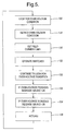
- Fig. 5 illustrates in schematic block form a method for operating a synchronous power generator in accordance with the present invention.
- the system looks for an over-voltage condition at 120 and upon the occurrence of such condition, the system detects the over-voltage condition at 124. If such condition exists, the field current limit is set at 126 and the switch controller operates the lower switches at 128 such that lower rectifiers to limit the output of the corresponding phase windings.
- the system continues to look for an over-voltage condition at 130. If the over-voltage condition persists, the conditions at 126 and 128 are maintained at 132. If the over-voltage condition subsides the system releases the field current maximum and releases the switch constraints at 134. Thereafter the system continues to look for a over-voltage condition as exemplified by the return to block 136. It should be understood that if a permanent magnet machine is employed the current limiting step 124 and corresponding release at 134 are not employed.
Landscapes
- Engineering & Computer Science (AREA)
- Power Engineering (AREA)
- Control Of Eletrric Generators (AREA)
Abstract
Description
- This invention relates generally to power generating systems, and, more particularly, to a system and method for controlling load dump voltage of a synchronous machine.
- A load dump condition is where the electrical load on the alternator, including the battery, goes instantly to zero, for example, via a broken or disconnected wire. A load dump test determines whether transients, for example, voltage transients output by the alternator under various conditions exceed a predetermined threshold. The threshold is selected to protect, for example, semiconductor devices that may draw power from the system as well as to protect the generator equipment as well. A load dump can, however, result in undesirable transients, for example, a voltage spike in the automobile electrical system which transients can cause damage to sensitive electrical and electronic systems.
- Typically a load dump apparatus may operate alone or in combination to short circuit the machine; disconnect the load from the machine; or clamp the voltage to some maximum level. For example, short circuiting the machine, while disconnecting the load including the battery, is an effective method to achieve the load dump in an automobile generator operating at or about the maximum output of the machine. However, if the battery is disconnected the system voltage may collapse and the automobile may stall before the system can reinitiate regulation.
- In an exemplary conventional system employing an alternator having a polyphase winding and a bridge circuit, when the load dump condition occurs, avalanche diodes employed in the bridge circuit short the phase windings, thereby limiting output voltage to the avalanche voltage limit of the diode. This limit is within the load dump threshold. However, high energy absorbing diodes are required, which increases the cost of the system.
- Hoffman et al., U.S. Patent No. 6,181,111, disclose an alternator for an automotive vehicle having a rotating permanent magnet (i.e., rotor) configured to induce a voltage in a stationary armature in which a three-phase winding is disposed. The winding is configured in a delta arrangement and is coupled to a bridge comprising six controlled rectifiers, an upper and lower rectifier for each phase. The rectifiers are disclosed as being silicon controlled rectifiers (SCRs). The alternator may be configured to produce a conventional output voltage of about 14.5 volts. Hoffman et al. further disclose a relatively complex circuit for responding to a load dump condition. The complex circuit increases cost and limits its usefulness in large scale production. Moreover, Hoffman et al. recognize that a high transient voltage may nonetheless exist for one alternation, notwithstanding the presence of the above complex circuit, and therefore provide for a metal oxide varistor (MOV) across the alternator output terminals as a limiting device. It is believed that such a device would have to be selected to dissipate a large amount of power and accordingly would be of increased cost which is undesirable.
- Peter, U.S. Patent No. 5,773,964, discloses an apparatus for controlling the output and torque of a synchronous alternator and employs a control bridge rectifier and a pulse width modulator (PWM) signal controlled field winding. The bridge in Peter is controlled for establishing a desired phase relationship between the alternating voltage and alternating current of the output winding to control the output and torque of the machine. While Peter discusses no load and short circuit conditions, Peter is concerned primarily with the control of the inductive characteristics of the circuit in order to vary the output and control the torque load on a machine.
- There is therefore a need for an improved power generating system that minimizes or eliminates one or more of the problems discussed hereinabove.
- The invention is based upon the discovery that, in an automotive electrical system employing a synchronous generator having polyphase windings, a field winding and a bridge having upper and lower electronically controlled switches operably connected to the polyphase windings, when an over-voltage is detected in any phase, the field is set to a predetermined level, the switches in the upper rectifier are set open so that the upper portion of the bridge operates as a diode bridge, and the lower switches are controlled in accordance with the corresponding current and voltage for the phase to which it is connected, so that each lower switch is off or open for a positive going part of the phase current, and when the phase current voltage exceeds a selected triggering level, the switch for the corresponding phase turns on shorting the phase winding for the remaining portion of the cycle. When the voltage falls below the trigger level the lower switch is turned off.
- In an exemplary embodiment the invention is directed to a power generating system comprising a synchronous machine including a multiphase stator winding output and corresponding outputs, and a field winding; a bridge including a pair of electronically controllable upper and lower switches for each phase coupled to the corresponding stator winding output and having a common node, the bridge having an output configured to be coupled to the battery and load of an automobile. A switch controller is operatively connected to open and close the switches to control the bridge output for operation at a predetermined first voltage corresponding to an operating voltage, and in response to an over-voltage condition to close the lower switches to control the bridge at a voltage lower than a first voltage. Concurrently with the over-voltage condition, the duty cycle of the field winding may be set to a predetermined level to insure that the system voltage is maintained at some minimum level. The invention is also operable for use in a permanent magnet synchronous machine.
- The invention may also be characterized as a load dump for a power generating system employing a synchronous machine having polyphase output windings producing a polyphase output and which includes a controlled rectifier bridge having an input coupled to the polyphase output windings and an output coupled between a direct voltage output terminal and ground terminal of the bridge. The bridge employs a plurality of electronically controllable switches, each being controllable to respective on and off conditions an accordance with a corresponding conduction signal applied thereto. The plurality of switches are arranged as series connected pairs between the output terminal and ground and have an intermediate node for each pair coupled to the polyphase winding. A switch controller responsively coupled to the output terminal of the bridge produces selected over-voltage conduction signals operative to turn off the upper switches and to turn on the lower switches when the output voltage is greater than or equal to a selected over-voltage condition, and to extinguish the over-voltage conduction signals when the output voltage falls to a level which is less than or equal to a nominal operating voltage below the over-voltage condition.
- The present invention will now be described, by way of example, with reference to the accompanying drawings, in which:
- Fig. 1 is a simplified schematic and block diagram of a power generation system employing a load dump feature according to the invention.
- Fig. 2 is a more detailed schematic diagram of the circuit shown in Fig. 1.
- Fig. 3 is a timing diagram illustrating the output voltage of the circuit of Fig. 1 with an unclamped over-voltage condition superimposed thereon.
- Fig. 4 is a wave form diagram showing the voltage recovery as a function of time.
- Fig. 5 is a block diagram showing the method steps.
-
- Referring now to the drawings wherein like reference numerals are used to identify identical components in the various views, Fig. 1 is a schematic block diagram of a
power generation system 10 which employs a load dump feature according to the invention. Thepower generation system 10 is adapted for use in automobile vehicles and advantageously employs asynchronous alternator 12 including a polyphase stator winding 14, abridge 16 employing electronicallycontrollable switches 18 and having aninput 20 coupled to the winding 14 and a directcurrent output 22. Abattery 24 is coupled to theoutput 22 of thebridge 16. One or moreelectrical loads 26 may be coupled to thebattery 24 via aswitch 28. Optionally a transient voltage limiting device such as a zener diode or avaristor 30 may be coupled across theload 22 as shown. Amaster controller 32, e.g., microprocessor or other appropriate device, is responsively coupled to theoutput 22 of thebridge 16 for producing conduction signals. Aswitch controller 34 is responsively coupled to themaster controller 32 and is operatively coupled to the electronically controlledswitches 18 ofbridge 16 to control gating the conduction signals. - The
alternator 12 has a rotor (not shown) which is driven at a variable speed by anengine 36 on a motor vehicle (also not shown). The rotor has a field winding 38 and asuppression diode 40 coupled in parallel as shown. A field exitation current Ie is provided to establish the magnetization of the rotor. As the rotor rotates, an alternating voltage VA, VB and VC is induced in each of thecorresponding windings - The
phase windings neutral point 42 and respective output nodes A, B and C as shown. The output winding 14 of the machine is characterized by generation of a plurality of alternating full cycles per phase. Nodes A, B and C are coupled toinput terminals input 20 of thebridge 16 for converting the three phase alternating voltage output of the winding to a direct voltage at theoutput 22 of the bridge between the output terminals 46 and 48 as illustrated. - Alternatively, a permanent magnet (PM) synchronous machine may be employed instead of a field excited machine. A wide variety of configurations are known to those of ordinary skill in the art for such permanent magnet alternatives. It should be understood that when a PM alternator is employed field control is not available. However, the load dump feature of the invention would be operable in either case with certain modifications which are hereinafter discussed.
-
Conductor 50 supplies the current to fieldcoil 38 frombattery 24 as shown. Field exitation current Ie is controlled in accordance with anelectronic switch 52, e.g., field effect transistor having agate 54 which receives a pulse width modulator (PWM) signal from themaster controller 32 overline 56. Thecontroller 32 is controlled in accordance with program instructions executed thereby. An overvoltage detector 60 monitors the output of thebridge 16 in order to determine if an over voltage condition exists. Upon the occurrence of such over voltage condition, thedetector 60 provides an input tomaster controller 32. - The
master controller 32 may further monitor an engine throttle position via aTPS sensor 62, which provides an input tomaster controller 32 online 64, to determine the desirability of reducing the torque load upon the engine as desired. Additionally,temperature sensor 66 may provide an temperature input to themaster controller 32 overline 68. The temperature sensed may represent a measure of battery temperature or other temperature correlated thereto. - In accordance to the invention when an over-voltage condition occurs the master controller produces the PWM signal having a selected pulse rate and applies the same to the
gate 54 of theswitch 52 which thereby controls and maintains the excitation current Ie at some selected minimal level, typically about 20% of maximum field current. This minimum excitation insures that the alternator produces a minimum current which in turn insures that the system voltage of the automobile does not collapse in the event that the generator output is diverted as hereinafter discussed. It should be understood, that the minimum excitation current may be further reduced to near zero if desired. It is simply desirable to maintain system voltage for a time sufficient to allow the alternator to recover from an overload condition and to enable it to regain regulation. Under normal operating conditions the PWM signal may be varied so as to increase the exitation current as load demand require. - As illustrated in Fig. 2, the bridge employs the electronically controlled
switches 18, which in the exemplary embodiment are arranged in pairs of series connected lower andupper switch elements 80L-80U, 82L-82U and 84L-84U for eachcorresponding phase switches 18 are connected as shown. Lower switch elements may be depicted a parallel combination of a normally opencontrollable switch 90 and adiode 92. Upper switch elements may likewise be depicted as a parallel combination of a normally open controllable switch 90' and diode 92'. When theswitch 90 is controlled to the open position the lower control operates as afree wheeling diode 92. When theswitch 90 is closed, the control rectifier operates as a short circuit. - In an exemplary embodiment the electronically controlled
switches 18 may take various forms. For example the switches may be in the form of FET switches or silicon control rectifiers (SCRs) or TRIAICs . The SCRs would be connected in anti parallel in the lower switches. Another expedient could employ a conventional bridge rectifier with three reverse SCRs in the lower switches. In the latter case the SCRs would be connected in is a conventional device which has a gate which may be energized to cause the device to conduct. An SCR is a latchable device which means that once gated on, it continues to conduct until the diode element sees a reversed bias at which point the SCR self commutates off. - In the exemplary embodiment each
switch element 80L-81U, 82L-82U and 84L-84U has a corresponding control terminal a-a1, b-b1 and c-c1, which in the exemplary embodiment, corresponds to the control for the switches 90-90' in each of the switch elements as described above. Theswitch control 34 has gate outputs 94, which have corresponding terminals a-a1, b-b1 and c-c1 coupled to the corresponding control terminals. -
Master controller 32 may produce normal conduction signals for the governing theswitch controller 34, for example when the system is operating at or below the maximum allowable voltage. When an over voltage condition occurs, as sensed either directly, or as shown, by the over voltage detector, themaster controller 32 may produce an alternative set of switch control signals for controlling theswitch controller 34. Alternatively, theswitch controller 34 may directly control the condition of the output terminals a-a1, b-b1 and c-c1 under normal conditions, and when an over voltage condition occurs theswitch controller 34 may be operative in response to the overvoltage detector 60 to select an alternative series of switch conditions to control the terminals a-a1, b-b1 and c-c1. - In the exemplary embodiment, the
switch controller 34 responsive to themaster controller 32 controls the conduction timing of outputs a, b, c-a1, b1, c1 for operating thebridge 16 under normal operating conditions, that is, when no over-voltage condition is sensed. Under such conditions, theswitches 90 and 90' are operated in accordance with conventional timing sequences to control the generator output. However, if an over-voltage condition is sensed, themaster controller 32 is responsive to produce different conduction timing signals and theswitch controller 34 controls the conductive states such thatswitch 90 inlower switch element 80L is closed for shunting out the corresponding phase winding and driving the output for the corresponding phase to zero.Switch 90 inlower switch element 80L remains closed shunting the phase winding 14A for the remaining portion of the phase. At the same time the upper switch 90' is open and diode 92' operates as free wheeling diode. If the over-voltage condition persists, then in a similar manner the switch 90' oflower rectifier 82L is closed to shunt the phase winding 14B for that portion of the cycle that the over voltage condition exists. Likewise, theswitch 90 oflower rectifier 84L is operated to shunt the phase winding 14C. In addition, when the over voltage condition exists, themaster controller 36 produces the appropriate PWM signal to limit the field current Ie. - As long as the over-voltage condition exists during any cycle the corresponding state of the switch element 90-90 in the
switches 18 are maintained and the field current is limited. However, when the over-voltage condition dissipates, thebridge 16 is enabled to operate under normal conditions and the limitation on the field excitation current is released. - Fig. 3 illustrates the output voltage of the bridge during an over-voltage condition. The dotted wave-form represents the uncontrolled or unclamped bridge output and the solid line wave-form represents the clamped or controlled voltage condition. An over-voltage condition exists when the unclamped output voltage of the
bridge 16 exceeds limit voltage VL. Upon the occurrence of an over-voltage condition in any phase, thegate controller 34 gates the correspondingswitch 90 in correspondinglower switch element - The dotted line wave-form depicts the output wave-form for one phase voltage only, namely phase A of winding 14A. It should be understood that
phase windings windings - As illustrated in Fig 4, when the over-voltage condition subsides, it typically falls below the limit value VX to some value and then recovers to the nominal value VN. The voltage passes through a knee K or minima in the curve. The field current is typically set so that the minima K does not diminish to zero or near zero volts V0 for any appreciable time which would cause the system voltage to collapse. If the response time of the system is fast, the excitation current may be reduced to allow the system voltage to approach zero without significantly risking system voltage collapse. If the system has a slower response time, then the value of the excitation current may be set at some higher value, for example, 20% which will allow the system voltage to fall below the limit and yet be sufficient to maintain the system voltage for a time sufficient for the system to recover.
- As noted above it is possible to operate the system using a permanent magnet (PM) synchronous motor. With such an arrangement it is not possible to employ field control to reduce the generator output. Accordingly, when the lower switches are closed, the machine current will increase to some maximum. Under such conditions, because the currents are essentially uncontrolled, it is necessary to provide for more robust switching elements. On the other hand, if a field control motor is employed, as illustrated hereinabove, when the windings are shorted, the system will produce a maximum current which corresponds to the field excitation current established by the PWM control. Accordingly, the energy dissipating capability of the rectifier switches may be significantly reduced.
- Fig. 5 illustrates in schematic block form a method for operating a synchronous power generator in accordance with the present invention. The system looks for an over-voltage condition at 120 and upon the occurrence of such condition, the system detects the over-voltage condition at 124. If such condition exists, the field current limit is set at 126 and the switch controller operates the lower switches at 128 such that lower rectifiers to limit the output of the corresponding phase windings. The system continues to look for an over-voltage condition at 130. If the over-voltage condition persists, the conditions at 126 and 128 are maintained at 132. If the over-voltage condition subsides the system releases the field current maximum and releases the switch constraints at 134. Thereafter the system continues to look for a over-voltage condition as exemplified by the return to block 136. It should be understood that if a permanent magnet machine is employed the current limiting
step 124 and corresponding release at 134 are not employed.
Claims (18)
- In an automobile electrical system (10) having an alternator (12) drivingly connected to a vehicle engine (36), the alternator having a polyphase output winding (14A, 14B, 14C) producing a polyphase output in the form of a polyphase alternator voltage (VA, VB, VC) for each phase, a load dump apparatus for varying the output of the alternator, a control bridge (16) coupled to said polyphase output winding and having a pair of direct voltage output terminals (48-46), said control bridge including a first switchable element (80L, 82L, 84L) and a second switchable element (80U, 82U, 84U) for each corresponding phase winding, said first and second switchable elements being connected in series across the output of the bridge and having a common input node (44A, 44B, 44C) connected to the corresponding phase winding, each controllable in accordance with a respective conduction signal applied thereto, characterized by a controller (32-34) for generating a plurality of conduction signals (a-a1, b-b1, c-c1) said conduction signals being applied to said first and second switchable elements for controlling the conduction thereof under normal operating condition and for controlling the switchable elements under an over voltage condition; and the normal operating condition occurs when the output voltage of each phase winding is up to a selected limit and the over-voltage condition occurs when the output voltage of any phase winding is above the selected limit, and the conduction of the first switching element for a phase being on for a time when the corresponding phase voltage is above the selected limit.
- An apparatus according to claim 1, wherein the first switchable elements (80L, 82L, 84L) are characterized by at least one of a rectifier, a silicon control rectifier, a field effect transistor and a TRIAC.
- An apparatus according to claim 1, further characterized by an over- voltage sensing device (60) for sensing an alternating voltage in each phase winding of the polyphase output winding and producing a voltage level signal therefrom.
- An apparatus according to claim 3 characterized by means for comparing (32-60) the phase voltage in each phase winding with a selected voltage limit to generate an over voltage signal, said controller (32-34) responsive to the signal for adjusting the conduction timing of the conduction signals so as to reduce the phase voltage to a desired level.
- An apparatus according to claim 1, wherein the first and second switchable elements are characterized by rectifiers (92, 92').
- The system according to claim 5 when the rectifiers comprise diodes being forward biased relative to the output coupled between the neutral point and ground.
- The system of claim 1, further characterized by at least one of a zener diode (30) and a varistor coupled to the bridge output.
- The system of claim 1, wherein the stator winding output is characterized by a three phase stator winding (14).
- The system of claim 1, wherein conduction control signals are characterized by gate pulses (a-a1, b-b1, c-c1) for respective switchable elements.
- The system of claim 1 wherein the over-voltage condition occurs when at least one of the phase voltages exceeds 14 volts.
- The system of claim 1, further characterized by a comparator (60) for comparing the output voltage with a reference indicative of an over-voltage condition.
- The system of claim 1 wherein the switchable elements for each phase is characterized by forward biased diodes.
- The system of claim 12, wherein the first switchable elements are characterized by a rectifier (90-92) and a parallel normally open switch (80U-80L) coupled thereto.
- The system of claim 1, wherein the alternator is characterized by at least one of a synchronous alternator (12) and a permanent magnet alternator.
- In an automotive electrical system (10) having an alternator (12) drivingly connected to a vehicle engine (36), said alternator having a polyphase output winding (14A, 14B, 14C) for producing a polyphase output in the form of a polyphase alternating voltage (VA, VB, VC) and a bridge (16) having a direct current output (44), including a first and second series connected switchable elements (80L-80U, 82L-82U, 84L-84U) for each phase coupled across the output and coupled to each corresponding phase winding at a neutral point (44) therebetween, a method for varying the output of the alternator characterized by generating a plurality of conduction signals (a-a1, b-b1, c-c1) for each corresponding phase of the polyphase alternating voltage, sensing the voltage in each phase winding of the polyphase output winding; applying the conduction signals to the switchable elemets of the bridge; comparing the output voltage with a selected voltage limit; and adjusting the conduction timing of the conduction signals for only the first switchable elements (80L, 82L, 84L) so as to reduce the voltage for the phase below the voltage limit.
- The method of claim 15, wherein the alternator has a field winding and further characterized by adjusting the current (Ie) in the field winding (38) to regulate the output voltage of the alternator.
- The method of claim 16 wherein the adjusting step further characterized by limiting the stator current to control the minimum output voltage of the alternator to a percentage of the maximum allowable output voltage during an over-voltage condition.
- The method of claim 15 wherein limiting the minimum output voltage is characterized by maintaining a minimum voltage sufficient to prevent system voltage collapse.
Applications Claiming Priority (2)
| Application Number | Priority Date | Filing Date | Title |
|---|---|---|---|
| US356959 | 1999-07-19 | ||
| US10/356,959 US6803748B2 (en) | 2003-02-03 | 2003-02-03 | System and method for controlling load dump voltage of a synchronous machine |
Publications (3)
| Publication Number | Publication Date |
|---|---|
| EP1443623A2 true EP1443623A2 (en) | 2004-08-04 |
| EP1443623A3 EP1443623A3 (en) | 2008-12-31 |
| EP1443623B1 EP1443623B1 (en) | 2017-11-01 |
Family
ID=32655612
Family Applications (1)
| Application Number | Title | Priority Date | Filing Date |
|---|---|---|---|
| EP04075271.9A Expired - Lifetime EP1443623B1 (en) | 2003-02-03 | 2004-01-30 | A system and method for controlling load dump voltage of a synchronous machine |
Country Status (2)
| Country | Link |
|---|---|
| US (2) | US6803748B2 (en) |
| EP (1) | EP1443623B1 (en) |
Cited By (9)
| Publication number | Priority date | Publication date | Assignee | Title |
|---|---|---|---|---|
| FR2874765A1 (en) * | 2004-08-31 | 2006-03-03 | Valeo Equip Electr Moteur | CONTROL AND POWER MODULE FOR A ROTATING ELECTRIC MACHINE |
| FR2917253A1 (en) * | 2007-06-08 | 2008-12-12 | Valeo Equip Electr Moteur | METHOD FOR CONTROLLING A ROTATING ELECTRICAL MACHINE IN THE EVENT OF CHARGE DELAY, AND CONTROL AND CORRESPONDING POWER MODULE |
| WO2011061200A1 (en) | 2009-11-23 | 2011-05-26 | Robert Bosch Gmbh | Preventing load rejection overvoltages in synchronous rectifiers |
| FR2962270A1 (en) * | 2010-06-30 | 2012-01-06 | Denso Corp | IMPROVED ELECTRICAL ROTATING MACHINE TO PROVIDE PROTECTION AGAINST POWER SUPPLY BREAKS |
| WO2012038436A1 (en) * | 2010-09-21 | 2012-03-29 | Robert Bosch Gmbh | Method and apparatus for operating an on-board electrical system of a vehicle |
| FR2975241A1 (en) * | 2011-05-10 | 2012-11-16 | Valeo Equip Electr Moteur | METHOD FOR CONTROLLING A ROTATING ELECTRIC MACHINE, CONTROL SYSTEM AND CORRESPONDING ROTATING ELECTRIC MACHINE |
| WO2014032894A2 (en) * | 2012-09-03 | 2014-03-06 | Robert Bosch Gmbh | Method for driving an active bridge rectifier in the event of load shedding, rectifier arrangement and computer program product |
| WO2015078685A1 (en) * | 2013-11-26 | 2015-06-04 | Robert Bosch Gmbh | Overvoltage protection for an on-board power supply of a motor vehicle during a load dump |
| EP2793391A4 (en) * | 2011-12-15 | 2016-08-03 | Mitsubishi Electric Corp | Power converter and control method for power converter |
Families Citing this family (30)
| Publication number | Priority date | Publication date | Assignee | Title |
|---|---|---|---|---|
| JP2003284378A (en) * | 2002-03-20 | 2003-10-03 | Denso Corp | Ac generator-motor apparatus for vehicle |
| US6803748B2 (en) * | 2003-02-03 | 2004-10-12 | Delphi Technologies, Inc. | System and method for controlling load dump voltage of a synchronous machine |
| US6876177B2 (en) * | 2003-02-04 | 2005-04-05 | General Motors Corporation | Load dump transient voltage controller |
| US7690573B2 (en) * | 2006-07-27 | 2010-04-06 | Spx Corporation | Alternator and starter tester with bar code functionality and method |
| US7212911B2 (en) * | 2004-10-29 | 2007-05-01 | Spx Corporation | Alternator and starter tester apparatus and method |
| JP4265548B2 (en) * | 2005-02-22 | 2009-05-20 | 株式会社デンソー | Power generation control device |
| US7215100B2 (en) * | 2005-03-21 | 2007-05-08 | Teleflex Canada Inc. | Generator transient regulator |
| NZ565921A (en) * | 2005-07-15 | 2011-05-27 | Southwest Windpower Inc | Wind turbine and method of manufacture |
| DE102006012215A1 (en) * | 2006-03-16 | 2007-09-20 | Mtu Aero Engines Gmbh | Transverse flux machine and turbomachinery with such Transversalflussmaschie |
| US7623331B2 (en) * | 2006-10-06 | 2009-11-24 | Remy International, Inc. | Method and system for improving voltage regulator accuracy in vehicle alternators |
| US7782023B2 (en) | 2006-11-30 | 2010-08-24 | Prestolite Electric, Inc. | Multipower voltage regulator |
| JP4270279B2 (en) * | 2007-01-05 | 2009-05-27 | 株式会社デンソー | Control device for vehicle alternator |
| US7952318B2 (en) * | 2007-06-04 | 2011-05-31 | Eaton Corporation | System and method for determining stator winding resistance in an AC motor |
| US8072191B2 (en) * | 2008-01-02 | 2011-12-06 | Hamilton Sundstrand Corporation | Shorted rotating diode detection and protection |
| US7915867B1 (en) * | 2008-04-25 | 2011-03-29 | Potenco, Inc. | Synchronous control for generator output |
| JP5495155B2 (en) * | 2008-10-02 | 2014-05-21 | 日立オートモティブシステムズ株式会社 | Control device for vehicle charging generator |
| US8497664B2 (en) * | 2009-11-19 | 2013-07-30 | GM Global Technology Operations LLC | High efficiency multi-phase generator |
| WO2012063287A1 (en) * | 2010-11-10 | 2012-05-18 | 国産電機株式会社 | Control device of rotating electrical machine |
| JP5293978B2 (en) * | 2011-04-18 | 2013-09-18 | 株式会社デンソー | Vehicle generator |
| US10055711B2 (en) | 2012-02-22 | 2018-08-21 | Bosch Automotive Service Solutions Inc. | Alternator and starter tester with warranty code functionality and method |
| US9128156B2 (en) | 2012-05-03 | 2015-09-08 | Bosch Automotive Service Solutions Inc. | Alternator and starter tester with other failures determination functionality and method |
| US8903595B2 (en) | 2012-09-17 | 2014-12-02 | Bosch Automotive Service Solutions Llc | Alternator and starter tester with increased load and cable identification |
| US9755557B2 (en) * | 2012-09-19 | 2017-09-05 | Mitsubishi Electric Corporation | Field-winding rotating electrical machine |
| DE102013208968A1 (en) * | 2013-05-15 | 2014-11-20 | Robert Bosch Gmbh | Motor vehicle electrical system with active bridge rectifier and overvoltage protection during load shedding, rectifier arrangement, associated operating method and means for its implementation |
| DE102013223316A1 (en) * | 2013-11-15 | 2015-05-21 | Robert Bosch Gmbh | Surge protection for motor vehicle electrical system with load shedding |
| JP6167989B2 (en) * | 2014-05-26 | 2017-07-26 | 株式会社デンソー | Vehicle generator |
| US9797956B2 (en) | 2015-11-24 | 2017-10-24 | Bosch Automotive Service Solutions Inc. | System and method for testing alternator default mode operation |
| US10193413B2 (en) | 2015-12-15 | 2019-01-29 | Bosch Automotive Service Solutions Inc. | Mounting bracket for water cooled type alternator |
| US11716111B2 (en) | 2021-05-06 | 2023-08-01 | Westinghouse Air Brake Technologies Corporation | Communication system and method |
| US11958512B2 (en) | 2019-12-20 | 2024-04-16 | Westinghouse Air Brake Technologies Corporation | Monitoring and communication device of a vehicle |
Citations (4)
| Publication number | Priority date | Publication date | Assignee | Title |
|---|---|---|---|---|
| US3931546A (en) * | 1974-05-28 | 1976-01-06 | C. E. Niehoff & Co. | Over-voltage protection circuit |
| US5793167A (en) * | 1995-09-05 | 1998-08-11 | Ford Global Technologies, Inc. | Operation of a motor vehicle alternator |
| US6353307B1 (en) * | 1998-08-05 | 2002-03-05 | Robert Bosch Gmbh | Controlled rectifier bridge with over-voltage protection |
| US20020171401A1 (en) * | 2001-05-21 | 2002-11-21 | Malakondaiah Naidu | System and method for controlling load dump voltage of a permanent magnet (PM) alternator |
Family Cites Families (31)
| Publication number | Priority date | Publication date | Assignee | Title |
|---|---|---|---|---|
| US3443197A (en) | 1965-08-13 | 1969-05-06 | Gen Motors Corp | Potential regulator circuit for permanent magnet type alternators |
| US3745441A (en) * | 1972-06-19 | 1973-07-10 | G Vidal | Self-excitation device for an alternator |
| US3943408A (en) | 1974-05-28 | 1976-03-09 | C. E. Niehoff & Co. | Over-voltage protection circuit for wye connected electric machine |
| JPH0655032B2 (en) | 1986-02-03 | 1994-07-20 | 株式会社日立製作所 | Current type converter protection device |
| AU608780B2 (en) | 1986-10-16 | 1991-04-18 | Clark Automotive Development Limited | Alternator and regulator for use therewith |
| US4815052A (en) * | 1988-07-06 | 1989-03-21 | Honeywell, Inc. | Automatic overvoltage protection circuit |
| US4885493A (en) | 1988-07-25 | 1989-12-05 | General Motors Corporation | Output voltage control apparatus of a permanent magnet alternator |
| JPH02219498A (en) * | 1989-02-16 | 1990-09-03 | Toyota Central Res & Dev Lab Inc | Current controller of inverter |
| US4959577A (en) | 1989-10-23 | 1990-09-25 | General Motors Corporation | Alternating current generator |
| US5214371A (en) | 1991-12-04 | 1993-05-25 | General Motors Corporation | Voltage regulator for variable speed permanent magnet alternators |
| US5376877A (en) * | 1992-06-11 | 1994-12-27 | Generac Corporation | Engine-driven generator |
| US5753989A (en) | 1993-06-14 | 1998-05-19 | Ecoair Corp. | Hybrid alternator |
| NZ274063A (en) * | 1993-09-17 | 1997-11-24 | Smithkline Beecham Corp | Cytokine suppressive anti-inflammatory drug binding protein (csbp) and its use |
| US5510696A (en) | 1994-11-03 | 1996-04-23 | General Motors Corporation | Zero current switching between winding sets in a permanent magnet alternator having a split winding stator |
| EP0717490B1 (en) | 1994-12-16 | 2003-05-21 | Delphi Technologies, Inc. | Output and torque control of an automotive alternator |
| JP3412330B2 (en) * | 1995-04-24 | 2003-06-03 | 株式会社デンソー | Power generation equipment for vehicles |
| FR2745445B1 (en) * | 1996-02-28 | 1998-05-07 | Valeo Electronique | VEHICLE ALTERNATOR USED AS A GENERATOR AND AN ELECTRIC MOTOR FOR STARTING THE VEHICLE'S INTERNAL COMBUSTION ENGINE |
| US5793625A (en) | 1997-01-24 | 1998-08-11 | Baker Hughes Incorporated | Boost converter regulated alternator |
| JP3168967B2 (en) * | 1997-09-12 | 2001-05-21 | トヨタ自動車株式会社 | Electric angle detecting device and method, and motor control device |
| FR2769771B1 (en) * | 1997-10-15 | 1999-12-31 | Valeo Equip Electr Moteur | DEVICE FOR THE SYNCHRONOUS RECTIFICATION OF AN ALTERNATOR |
| DE19849889A1 (en) * | 1998-10-29 | 2000-05-04 | Bosch Gmbh Robert | Process for the performance and efficiency-optimized control of synchronous machines |
| US6022219A (en) * | 1998-12-18 | 2000-02-08 | Cohen; Elise | Painting kit and related method |
| US6081084A (en) * | 1999-05-12 | 2000-06-27 | Delco Remy America, Inc. | Sensorless power angle control for a vehicle alternator |
| US6181111B1 (en) | 1999-07-21 | 2001-01-30 | Lowell T. Hoffman | Permanent magnet alternator system for battery charging |
| US6239582B1 (en) * | 1999-11-04 | 2001-05-29 | Satcon Technology Corporation | Motor vehicle alternator having a single voltage sensor and a half-wave controlled rectifier bridge for increasing output |
| US6566829B1 (en) | 2000-09-07 | 2003-05-20 | Delphi Technologies, Inc. | Method and apparatus for torque control of a machine |
| US6407531B1 (en) | 2001-01-09 | 2002-06-18 | Delphi Technologies, Inc. | Method and system for controlling a synchronous machine over full operating range |
| US6590361B2 (en) | 2001-07-19 | 2003-07-08 | Delphi Technologies, Inc. | Method and system for controlling an induction machine |
| US6577097B2 (en) | 2001-08-13 | 2003-06-10 | Delphi Technologies, Inc. | Method and system for controlling a synchronous machine using a changeable cycle-conduction angle |
| JP4438261B2 (en) * | 2001-08-31 | 2010-03-24 | 株式会社デンソー | Vehicle alternator |
| US6803748B2 (en) * | 2003-02-03 | 2004-10-12 | Delphi Technologies, Inc. | System and method for controlling load dump voltage of a synchronous machine |
-
2003
- 2003-02-03 US US10/356,959 patent/US6803748B2/en not_active Expired - Lifetime
-
2004
- 2004-01-30 EP EP04075271.9A patent/EP1443623B1/en not_active Expired - Lifetime
- 2004-10-08 US US10/962,344 patent/US20050046397A1/en not_active Abandoned
Patent Citations (4)
| Publication number | Priority date | Publication date | Assignee | Title |
|---|---|---|---|---|
| US3931546A (en) * | 1974-05-28 | 1976-01-06 | C. E. Niehoff & Co. | Over-voltage protection circuit |
| US5793167A (en) * | 1995-09-05 | 1998-08-11 | Ford Global Technologies, Inc. | Operation of a motor vehicle alternator |
| US6353307B1 (en) * | 1998-08-05 | 2002-03-05 | Robert Bosch Gmbh | Controlled rectifier bridge with over-voltage protection |
| US20020171401A1 (en) * | 2001-05-21 | 2002-11-21 | Malakondaiah Naidu | System and method for controlling load dump voltage of a permanent magnet (PM) alternator |
Cited By (25)
| Publication number | Priority date | Publication date | Assignee | Title |
|---|---|---|---|---|
| WO2006027481A1 (en) * | 2004-08-31 | 2006-03-16 | Valeo Equipements Electriques Moteur | Control and power module for a rotating electrical machine |
| US7629776B2 (en) | 2004-08-31 | 2009-12-08 | Valeo Equipments Electriques Moteur | Control and power module for a rotating electrical machine |
| FR2874765A1 (en) * | 2004-08-31 | 2006-03-03 | Valeo Equip Electr Moteur | CONTROL AND POWER MODULE FOR A ROTATING ELECTRIC MACHINE |
| US8294412B2 (en) | 2007-06-08 | 2012-10-23 | Valeo Equipements Electriques Moteur | Method for controlling a rotary electric machine in case of load shedding and corresponding power control module |
| FR2917253A1 (en) * | 2007-06-08 | 2008-12-12 | Valeo Equip Electr Moteur | METHOD FOR CONTROLLING A ROTATING ELECTRICAL MACHINE IN THE EVENT OF CHARGE DELAY, AND CONTROL AND CORRESPONDING POWER MODULE |
| WO2009000989A2 (en) * | 2007-06-08 | 2008-12-31 | Valeo Equipements Electriques Moteur | Method for controlling a rotary electric machine in case of load shedding and corresponding power control module |
| WO2009000989A3 (en) * | 2007-06-08 | 2009-03-19 | Valeo Equip Electr Moteur | Method for controlling a rotary electric machine in case of load shedding and corresponding power control module |
| CN101682287B (en) * | 2007-06-08 | 2013-02-06 | 法雷奥电机设备公司 | Method for controlling a rotary electric machine in case of load shedding, corresponding control and power module |
| WO2011061200A1 (en) | 2009-11-23 | 2011-05-26 | Robert Bosch Gmbh | Preventing load rejection overvoltages in synchronous rectifiers |
| CN102668364A (en) * | 2009-11-23 | 2012-09-12 | 罗伯特·博世有限公司 | Preventing load rejection overvoltages in synchronous rectifiers |
| CN102668364B (en) * | 2009-11-23 | 2015-02-25 | 罗伯特·博世有限公司 | Preventing load rejection overvoltages in synchronous rectifiers |
| FR2962270A1 (en) * | 2010-06-30 | 2012-01-06 | Denso Corp | IMPROVED ELECTRICAL ROTATING MACHINE TO PROVIDE PROTECTION AGAINST POWER SUPPLY BREAKS |
| WO2012038436A1 (en) * | 2010-09-21 | 2012-03-29 | Robert Bosch Gmbh | Method and apparatus for operating an on-board electrical system of a vehicle |
| WO2012172216A1 (en) * | 2011-05-10 | 2012-12-20 | Valeo Equipements Electriques Moteur | Method of controlling a rotating electric machine, control system and rotating electric machine corresponding thereto |
| FR2975241A1 (en) * | 2011-05-10 | 2012-11-16 | Valeo Equip Electr Moteur | METHOD FOR CONTROLLING A ROTATING ELECTRIC MACHINE, CONTROL SYSTEM AND CORRESPONDING ROTATING ELECTRIC MACHINE |
| US9354622B2 (en) | 2011-05-10 | 2016-05-31 | Valeo Equipements Electriques Moteur | Method of controlling a rotating electric machine, control system and rotating electric machine corresponding thereto |
| EP2793391A4 (en) * | 2011-12-15 | 2016-08-03 | Mitsubishi Electric Corp | Power converter and control method for power converter |
| WO2014032894A2 (en) * | 2012-09-03 | 2014-03-06 | Robert Bosch Gmbh | Method for driving an active bridge rectifier in the event of load shedding, rectifier arrangement and computer program product |
| WO2014032894A3 (en) * | 2012-09-03 | 2014-06-12 | Robert Bosch Gmbh | Method for driving an active bridge rectifier in the event of load shedding, rectifier arrangement and computer program product |
| CN104584355A (en) * | 2012-09-03 | 2015-04-29 | 罗伯特·博世有限公司 | Method for driving active bridge rectifier in the event of load shedding, rectifier arrangement and computer program product |
| CN104584355B (en) * | 2012-09-03 | 2017-12-26 | 罗伯特·博世有限公司 | For manipulating method, rectifier unit and the computer program product of active bridge rectification device when loading and reducing |
| US9985625B2 (en) | 2012-09-03 | 2018-05-29 | Seg Automotive Germany Gmbh | Method for controlling an active bridge rectifier during load shedding, rectifier system, and computer program product |
| WO2015078685A1 (en) * | 2013-11-26 | 2015-06-04 | Robert Bosch Gmbh | Overvoltage protection for an on-board power supply of a motor vehicle during a load dump |
| CN105745806A (en) * | 2013-11-26 | 2016-07-06 | 罗伯特·博世有限公司 | Overvoltage protection for an on-board power supply of a motor vehicle during a load dump |
| CN105745806B (en) * | 2013-11-26 | 2018-10-16 | 索恩格汽车德国有限责任公司 | For carried on vehicle power grid in the case that removal of load overvoltage protection |
Also Published As
| Publication number | Publication date |
|---|---|
| US6803748B2 (en) | 2004-10-12 |
| US20050046397A1 (en) | 2005-03-03 |
| EP1443623B1 (en) | 2017-11-01 |
| US20040150376A1 (en) | 2004-08-05 |
| EP1443623A3 (en) | 2008-12-31 |
Similar Documents
| Publication | Publication Date | Title |
|---|---|---|
| EP1443623B1 (en) | A system and method for controlling load dump voltage of a synchronous machine | |
| KR102087573B1 (en) | Operating state circuit for an inverter and method for setting operating states of an inverter | |
| CN111095773B (en) | Soft starter AC-AC converter with integrated solid state circuit breaker and method of operating the same | |
| US7239099B2 (en) | Circuit configuration and method for controlling an electric motor, in particular of a washing machine | |
| US7453240B2 (en) | Generating apparatus and motor control apparatus | |
| US10186997B2 (en) | Overvoltage arrester for an electrical drive | |
| US20120281446A1 (en) | Preventing load dump overvoltages in synchronous rectifiers, | |
| JP6053052B2 (en) | Method for controlling a rotary electric machine, also a control system, and a rotary electric machine | |
| US5805394A (en) | Overvoltage protection circuit for a generating system utilizing a fault current sensing Circuit in combination with a shunting circuit | |
| US20010052761A1 (en) | Vehicular AC generator having voltage control unit | |
| US20160294181A1 (en) | Overvoltage protection for a motor vehicle electrical system in the event of load shedding | |
| JP3627047B2 (en) | Voltage controller that controls the output voltage of the generator | |
| JP4673539B2 (en) | Excitation current controller for three-phase AC generator | |
| US4594632A (en) | Overvoltage protection circuit for synchronous machinerotor | |
| EP2061148B1 (en) | Protection of variable frequency power systems from excessive peak electrical potentials | |
| US7276882B2 (en) | Regulator control circuit and method | |
| JPH0681560B2 (en) | Device for limiting the terminal voltage of an alternator | |
| AU2020316661A1 (en) | Overcurrent protection device for a direct current network | |
| JPH041571B2 (en) | ||
| SU1545284A1 (en) | Device for protection of brushless synchronous machine against damage in excitation system | |
| US6906480B2 (en) | Regulator control circuit and method | |
| JPH0337000A (en) | Generation controller | |
| AU2021269391A1 (en) | An Alternator Stator Clamping Device | |
| JP2611972B2 (en) | Super-synchronous cervius device | |
| JP2000236624A (en) | Single-phase three-wire circuit breaker and method for detecting its open phase |
Legal Events
| Date | Code | Title | Description |
|---|---|---|---|
| PUAI | Public reference made under article 153(3) epc to a published international application that has entered the european phase |
Free format text: ORIGINAL CODE: 0009012 |
|
| AK | Designated contracting states |
Kind code of ref document: A2 Designated state(s): AT BE BG CH CY CZ DE DK EE ES FI FR GB GR HU IE IT LI LU MC NL PT RO SE SI SK TR |
|
| AX | Request for extension of the european patent |
Extension state: AL LT LV MK |
|
| PUAL | Search report despatched |
Free format text: ORIGINAL CODE: 0009013 |
|
| AK | Designated contracting states |
Kind code of ref document: A3 Designated state(s): AT BE BG CH CY CZ DE DK EE ES FI FR GB GR HU IE IT LI LU MC NL PT RO SE SI SK TR |
|
| AX | Request for extension of the european patent |
Extension state: AL LT LV MK |
|
| 17P | Request for examination filed |
Effective date: 20090630 |
|
| AKX | Designation fees paid |
Designated state(s): DE FR GB |
|
| 17Q | First examination report despatched |
Effective date: 20160520 |
|
| GRAP | Despatch of communication of intention to grant a patent |
Free format text: ORIGINAL CODE: EPIDOSNIGR1 |
|
| INTG | Intention to grant announced |
Effective date: 20170606 |
|
| GRAS | Grant fee paid |
Free format text: ORIGINAL CODE: EPIDOSNIGR3 |
|
| GRAA | (expected) grant |
Free format text: ORIGINAL CODE: 0009210 |
|
| AK | Designated contracting states |
Kind code of ref document: B1 Designated state(s): DE FR GB |
|
| REG | Reference to a national code |
Ref country code: GB Ref legal event code: FG4D |
|
| REG | Reference to a national code |
Ref country code: DE Ref legal event code: R081 Ref document number: 602004051985 Country of ref document: DE Owner name: DELPHI TECHNOLOGIES IP LIMITED, BB Free format text: FORMER OWNER: DELPHI TECHNOLOGIES, INC., TROY, MICH., US |
|
| REG | Reference to a national code |
Ref country code: DE Ref legal event code: R096 Ref document number: 602004051985 Country of ref document: DE |
|
| REG | Reference to a national code |
Ref country code: DE Ref legal event code: R097 Ref document number: 602004051985 Country of ref document: DE |
|
| PLBE | No opposition filed within time limit |
Free format text: ORIGINAL CODE: 0009261 |
|
| STAA | Information on the status of an ep patent application or granted ep patent |
Free format text: STATUS: NO OPPOSITION FILED WITHIN TIME LIMIT |
|
| 26N | No opposition filed |
Effective date: 20180802 |
|
| GBPC | Gb: european patent ceased through non-payment of renewal fee |
Effective date: 20180201 |
|
| PG25 | Lapsed in a contracting state [announced via postgrant information from national office to epo] |
Ref country code: FR Free format text: LAPSE BECAUSE OF NON-PAYMENT OF DUE FEES Effective date: 20180131 |
|
| REG | Reference to a national code |
Ref country code: FR Ref legal event code: ST Effective date: 20180928 |
|
| REG | Reference to a national code |
Ref country code: DE Ref legal event code: R081 Ref document number: 602004051985 Country of ref document: DE Owner name: DELPHI TECHNOLOGIES IP LIMITED, BB Free format text: FORMER OWNER: DELPHI TECHNOLOGIES, INC., TROY, MICH., US |
|
| PG25 | Lapsed in a contracting state [announced via postgrant information from national office to epo] |
Ref country code: GB Free format text: LAPSE BECAUSE OF NON-PAYMENT OF DUE FEES Effective date: 20180201 |
|
| PGFP | Annual fee paid to national office [announced via postgrant information from national office to epo] |
Ref country code: DE Payment date: 20221215 Year of fee payment: 20 |
|
| P01 | Opt-out of the competence of the unified patent court (upc) registered |
Effective date: 20230327 |
|
| REG | Reference to a national code |
Ref country code: DE Ref legal event code: R071 Ref document number: 602004051985 Country of ref document: DE |