BACKGROUND OF THE INVENTION
This application claims the benefit of a
Japanese Patent Application No.2003-025060 filed
January 31, 2003, in the Japanese Patent Office, the
disclosure of which is hereby incorporated by
reference.
1. Field of the Invention
The present invention generally relates to
methods and apparatuses for controlling array
antennas and computer-readable storage media, and
more particularly to an array antenna control method
and an array antenna control apparatus for
controlling an array antenna in a mobile station or
a base station of a wireless Local Area Network
(LAN) system, a mobile communication system and the
like, and to a computer-readable storage medium
which stores a program for causing a computer to
control an array antenna.
2. Description of the Related Art
Recently, due to increased demands on
large-capacity communications via the Internet,
rapid technical developments have been made to
increase the capacity of wireless networks such as
portable telephone networks and wireless LANs. In
order to realize a high-speed wireless communication,
it is necessary to overcome the fading caused by
multipath propagation of radio waves. The
application of the Orthogonal Frequency Division
Multiplexing (OFDM) is regarded as a promising
countermeasure against the fading.
The OFDM is one of multicarrier modulation
techniques, and the subcarriers are arranged to
maintain a mutual orthogonal relationship. For this
reason, it is possible to improve the frequency
utilization efficiency compared to the conventional
transmission using the single multicarrier. In
addition, the OFDM is less likely to be affected by
the frequency selective fading because the
transmission speed may be regarded as being low-speed.
Furthermore, since a guard interval is
inserted at the beginning of each symbol, it is
possible to reduce the effects of delayed waves.
Accordingly, the OFDM is uneasily affected
by the multipath environment. However, when
interference waves, such as Doppler shift waves
subjected to Doppler frequency deviation due to
moving, interference waves from other systems and
delayed waves exceeding the guard interval, are
received, Inter-Carrier Interference (ICI), InterSymbol
Interference (ISI) and the like are generated,
to greatly deteriorate the receiving characteristics
such as the Bit Error Rate (BER). Hence,
interference suppression techniques using adaptive
array antennas have been proposed, as will be
described hereinafter with reference to FIGS. 1 and
2.
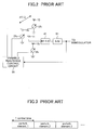
FIG. 1 is a system block diagram showing a
structure of an example of a conventional adaptive
antenna control apparatus. The conventional
adaptive antenna control apparatus shown in FIG. 1
controls an array antenna section which is formed by
a plurality of antenna elements 101 through 10M, and
includes antenna weighting circuits 201 through 20M,
a combining circuit (Σ) 30, a radio frequency front
end (RF F/E) section 40, a an analog-to-digital
(A/D) converter 50, and a weighting control circuit
60. Signals which are combined in the combining
circuit 30, and an output signal of the combining
circuit 30 is subjected to processes such as band
limitation and frequency conversion in the RF F/E
section 40, before being converted into a digital
signal by the A/D converter 50. The weighting
control circuit 60 adaptively controls the antenna
weighting circuits 201 through 20M of the array
antenna elements 101 through 10M, so that the signal
after the A/D conversion (that is, the receiver
input) has a largest Signal-To-Interference Plus
Noise (SINR). As a result, a directional beam is
formed with respect to the desired wave, and a null
antenna directivity is formed with respect to the
interference wave to null out the interference wave.
The adaptive array antenna control
apparatus described above has a complex hardware
structure and is expensive, and in addition, it is
difficult to reduce the power consumption. Thus, it
is difficult to apply the adaptive array antenna
control apparatus to small wireless terminals such
as a portable telephone set, thereby limiting the
application of the adaptive array antenna control
apparatus.
An adaptive array antenna control
apparatus which enables both the cost and the power
consumption to be reduced, has also been proposed.
This proposed adaptive array antenna control
apparatus requires only one power supply system and
one receiving system, thereby making the hardware
structure simple and suited for use in small
wireless terminals such as the portable telephone
set. This proposed adaptive array antenna control
apparatus is often referred to as an Electronically
Steerable Parasitic Array Radiator (ESPAR) antenna.
The ESPAR antenna arranges passive antenna elements
in a circular manner around an active antenna
element, and electronically controls reactances of
variable reactances load-terminating the passive
antenna elements, so as to control the radiation
beam pattern within the horizontal plane (horizontal
radiation pattern).
FIG. 2 is a system block diagram showing a
structure of an example of a conventional adaptive
array antenna control apparatus for the ESPAR
antenna. The adaptive array antenna control
apparatus shown in FIG. 2 controls an array antenna
section which is formed by one active antenna
element 11 and three passive antenna elements 121
through 123, and includes variable reactance
circuits 211 through 213, a radio frequency front
end (RF F/E) section 41, an analog-to-digital (A/D)
converter 51, and a variable reactance control
circuit 61. A received signal from the active
antenna element 11 is passed through the RF F/E
section 41 and is converted into a digital signal by
the A/D converter 51. In addition, the received
signal from the active antenna element 11 is
affected by electromagnetic mutual coupling of the
surrounding passive antenna elements 121 through 123.
The variable reactance control circuit 61 adaptively
controls the variable reactance circuits 211 through
213 of the passive antenna elements 121 through 123
so that the signal after the A/D conversion (that is,
the receiver input) has a largest SINR. As a result,
a directional beam is formed with respect to the
desired wave, and a null antenna directivity is
formed with respect to the interference wave to null
out the interference wave.
As described above, the received signals
cannot be obtained from all of the antenna elements
of the ESPAR antenna. For this reason, the control
algorithm employed for the normal adaptive array
antenna cannot be used for the ESPAR antenna. Hence,
a steepest gradient algorithm using the perturbation
method has been proposed in Cheng et al., "Adaptive
Beamforming of ESPAR Antenna Based on Steepest
Gradient Algorithm", IEICE TRANS. COMMUN., VOL.E84-B,
NO.7 July 2001, as a control algorithm which takes
into consideration the characteristics of the ESPAR
antenna. The control algorithm using the
perturbation method changes the reactance of one
passive antenna element by a predetermined amount,
and while observing a predetermined evaluation
function, the reactance is changed in a direction
such that the reception characteristics after the
change improve from that before the change.
Furthermore, a similar operation is performed with
respect to the other passive antenna elements, so as
to obtain the desired directivity.
FIG. 3 is a diagram for explaining an
antenna weighting time based on the perturbation
method. More particularly, FIG. 3 shows weighting
perturbation times of the passive antenna elements
121 through 123 for a case where the signal received
by the active antenna element 11 is an OFDM signal
in the ESPAR antenna employing the control algorithm
which uses the perturbation method.
According to the OFDM, the signal is
modulated and transmitted in predetermined units
called symbols. At the time of the reception, it is
necessary to carry out a demodulation process by
sectioning the received signal for every symbol.
Hence, according to the conventional control
algorithm which uses the perturbation method, the
reactances of the passive antenna elements 121
through 123 are perturbed for every symbol. For
example, the reactance of the first passive antenna
element 121 is perturbed at the first symbol, the
reactance of the second passive antenna element 122
is perturbed at the next symbol, the reactance of
the third passive antenna element 123 is perturbed
at the next symbol, ..., as shown in FIG. 3, so that
the reactance of one passive antenna element is
perturbed for every symbol. Moreover, the reactance
of each of the passive antenna elements 121 through
123 is updated so that the SINR increases, while
observing the virtual subcarrier component
(subcarrier not used for the data communication).
However, if the control algorithm which
uses the perturbation method is employed for a
plurality of passive antenna elements, it requires a
number of symbols amounting to the number of antenna
elements to update the reactance of each passive
antenna elements. For this reason, there were
problems in that it requires a long time for the
control algorithm to converge, and that the
interference waves cannot be suppressed sufficiently
until the control algorithm converges.
SUMMARY OF THE INVENTION
Accordingly, it is a general object of the
present invention to provide a novel and useful
array antenna control method, array antenna control
apparatus and computer-readable storage medium, in
which the problems described above are eliminated.
Another and more specific object of the
present invention is to provide an array antenna
control method, an array antenna control method and
a computer-readable storage medium, which can update
antenna weighting (weighting coefficients) at a high
speed.
Still another object of the present
invention is to provide a method of controlling an
array antenna part having a plurality of antenna
elements arranged at a predetermined interval,
comprising obtaining a predetermined evaluation
function with respect to each of weighting
coefficients to be applied to incoming signals
arriving at a predetermined number of antenna
elements, by perturbing each of the weighting
coefficients at a sampling interval which is within
one symbol time; and adjusting each of the weighting
coefficients based on the evaluation function.
According to the array antenna control method of the
present invention, it is possible to update the
antenna weighting coefficients at a high speed, and
converge the optimizing algorithm at a high speed
while suppressing the interference wave.
A further object of the present invention
is to provide an array antenna control apparatus for
controlling an array antenna part having a plurality
of antenna elements arranged at a predetermined
interval, comprising a control unit having a part to
obtain a predetermined evaluation function with
respect to each of weighting coefficients to be
applied to incoming signals arriving at a
predetermined number of antenna elements, by
perturbing each of the weighting coefficients at a
sampling interval which is within one symbol time,
and a part to adjust each of the weighting
coefficients based on the evaluation function.
According to the array antenna control method of the
present invention, it is possible to update the
antenna weighting coefficients at a high speed, and
converge the optimizing algorithm at a high speed
while suppressing the interference wave.
Another object of the present invention is
to provide an array antenna control apparatus for
controlling an array antenna part having,a plurality
of antenna elements arranged at a predetermined
interval, comprising control means comprising means
for obtaining a predetermined evaluation function
with respect to each of weighting coefficients to be
applied to incoming signals arriving at a
predetermined number of antenna elements, by
perturbing each of the weighting coefficients at a
sampling interval which is within one symbol time,
and means for adjusting each of the weighting
coefficients based on the evaluation function.
According to the array antenna control apparatus of
the present invention, it is possible to update the
antenna weighting coefficients at a high speed, and
converge the optimizing algorithm at a high speed
while suppressing the interference wave.
Still another object of the present
invention is to provide a computer-readable storage
medium which stores a program for causing a computer
to control an array antenna part having a plurality
of antenna elements arranged at a predetermined
interval, the comprising a procedure causing the
computer to obtain a predetermined evaluation
function with respect to each of weighting
coefficients to be applied to incoming signals
arriving at a predetermined number of antenna
elements, by perturbing each of the weighting
coefficients at a sampling interval which is within
one symbol time; and a procedure causing the
computer to adjust each of the weighting
coefficients based on the evaluation function.
According to the computer-readable storage medium of
the present invention, it is possible to update the
antenna weighting coefficients at a high speed, and
converge the optimizing algorithm at a high speed
while suppressing the interference wave.
Other objects and further features of the
present invention will be apparent from the
following detailed description when read in
conjunction with the accompanying drawings.
BRIEF DESCRIPTION OF THE DRAWINGS
FIG. 1 is a system block diagram showing a
structure of an example of a conventional adaptive
antenna control apparatus;
FIG. 2 is a system block diagram showing a
structure of an example of a conventional adaptive
array antenna control apparatus for an ESPAR
antenna;
FIG. 3 is a diagram for explaining an
antenna weighting time based on the perturbation
method;
FIG. 4 is a system block diagram showing a
structure of an embodiment of the array antenna
control apparatus according to the present
invention;
FIG. 5 is a diagram showing a subcarrier
arrangement of an OFDM signal in conformance with
the IEEE802.11a;
FIG. 6 is a diagram showing variable
reactance perturbation times of passive antenna
elements;
FIG. 7 is a diagram for explaining a
variable reactance perturbation time of the passive
antenna element;
FIG. 8 is a flow chart for explaining a
reactance control process of a variable reactance
control circuit with respect to the passive antenna
elements;
FIG. 9 is a diagram showing a structure of
a PLCP preamble in conformance with IEEE802.11a;
FIG. 10 is a diagram showing a convergence
characteristic of an evaluation function ρm(n) with
respect to a number of tries, n, in a state where no
noise exists;
FIG. 11 is a diagram showing a horizontal
directivity pattern in a state shown in FIG. 14
where a desired wave signal S (1 wave) arrives from
a 0° direction and an interference wave I (1 wave)
arrives from a 100° direction, in the state where no
noise exists;
FIG. 12 is a diagram showing a convergence
characteristic of the evaluation function ρm(n) with
respect to the number of tries, n, in a state where
noise exists;
FIG. 13 is a diagram showing a horizontal
directivity pattern in the state shown in FIG. 14
where the desired wave signal S (1 wave) arrives
from the 0° direction and the interference wave I (1
wave) arrives from the 100° direction, in the state
where the noise exists;
FIG. 14 is a diagram showing a model of
signal sources used in obtaining simulation results
for the embodiment of the array antenna control
apparatus;
FIG. 15 is a diagram for explaining a
weighting coefficient updating process which is
carried out by selecting a diversity branch; and
FIG. 16 is a diagram for explaining a
weighting coefficient updating process which is
carried out by combining diversity branches.
DESCRIPTION OF THE PREFERRED EMBODIMENTS
A description will now be given of an
embodiment of an array antenna control method
according to the present invention, an embodiment of
an array antenna control apparatus according to the
present invention, and an embodiment of a computer-readable
storage medium according to the present
invention, by referring to FIGS. 4 through 16.
In this embodiment, the present invention
is applied to a wireless communication system
employing the multicarrier transmission, such as the
wireless LAN system in conformance with the IEEE
802.11a standard (employing OFDM), which converts a
transmitting data sequence into a plurality of data
sequences by a serial-to-parallel conversion and
makes a wireless parallel transmission of the
plurality of data sequences by use of a plurality of
carriers having mutually different frequencies. In
addition, it is assumed for the sake of convenience
that this embodiment uses the frame format
prescribed by the IEEE 802.11a standard.
The present invention relates to the array
antenna control for an array antenna which is used
in such a wireless communication system.
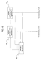
FIG. 4 is a system block diagram showing a
structure of this embodiment of the array antenna
control apparatus. The array antenna control
apparatus shown in FIG. 4 controls an array antenna
section which is formed by one active antenna
element and six passive antenna elements 141 through
146, and includes variable reactance circuits 221
through 226, a radio frequency front end (RF F/E)
section 42, an analog-to-digital (A/D) converter 52,
a Fourier transform section 70, and a variable
reactance control circuit 80. The variable
reactance control circuit 80 may be formed by a
digital computing unit such as a computer, for
example.
In FIG. 4, a radio signal transmitted from
an OFDM transmitter of the other (transmitting) end
is received by the active antenna element 13. The
received signal is input to the FR F/E section 42
which carries out processes such as low-noise
amplification and frequency conversion into the
intermediate frequency or base band, and then
converted into a digital signal by the A/D converter
52. The digital signal on the time base (time-based
digital signal), which is output from the A/D
converter 52, is converted into a signal on the
frequency base (frequency-based signal) by the
Fourier transform section 70, before being input to
the variable reactance control circuit 80. In
addition, the output of the Fourier transform
section 70 is supplied to a next stage, such as a
demodulator, to be subjected to a data demodulation
process and the like. The variable reactance
control circuit 80 computes a correlation between
the received signal which has been converted into
the signal on the frequency base (frequency-based
signal) and a predetermined known signal which will
be described later, and updates weighting
coefficients of the passive antenna elements 141
through 146. In this case, the weighting
coefficients are the reactances of the passive
antenna elements 141 through 146. The updated
weighting coefficients, that is, the updated
reactances, are supplied to the variable reactance
circuits 221 through 226 to control the directivity.
The weighting coefficients of the passive
antenna elements 141 through 146 vary bias voltages
applied to variable capacitance diodes, so as to
vary electrostatic capacitances of the variable
capacitance diodes. Hence, it is possible to vary
an electrical length of variable reactance elements
of the passive antenna elements 141 through 146 in
comparison to that of the active antenna element 13,
and vary the radiation beam pattern of the array
antenna.
Next, a description will be given of a
reactance control process (updating process) for the
passive antenna elements 141 through 146, which is
carried out by the array antenna control apparatus
described above, by referring to FIG. 5. FIG. 5 is
a diagram showing a subcarrier arrangement of the
OFDM signal in conformance with the IEEE802.11a.
In FIG. 5, the number Ns of subcarriers is
"64", and subcarriers which actually transmit the
data are indicated by solid lines with indexes -26
through -1 and 1 through 26, while virtual
subcarriers which actually do not transmit the data
are indicated by broken lines with indexes -32
through -27, 0 and 27 through 31. Hence in this
particular case, the communication is made using 52
subcarriers.
Next, a description will be given of
variable reactance perturbation times (or
perturbation speeds) of the passive antenna elements
141 through 146, by referring to FIG. 6. FIG. 6 is
a diagram showing the variable reactance
perturbation times of the passive antenna elements
141 through 146.
In this embodiment, an 8-times over-sampling
is performed in the A/D converter 52, in
order to update the antenna weighting (reactance of
the variable reactance) for every symbol. In other
words, the number of samples in the A/D conversion
is 512 (= (number of subcarriers) · 8 = 64·8) within
one symbol time (3.2 µs).
When one symbol is formed by 512 sampled
data this manner, the effects of the perturbation of
the passive antenna elements 141 through 146 on the
reception characteristics is observed. More
particularly, only a reactance x1 of the first
passive antenna element 141 (#1) is perturbed by a
small amount Δx at the first sample, and the
received signal is measured thereafter. Next, at
the second sample, a reactance x2 of the second
passive antenna element 142 (#2) is perturbed by the
small amount Δx, and the received signal is measured
thereafter. Such an operation is carried out up to
the sixth sample, so that a reactance x6 of the
sixth passive antenna element 146 (#6) is perturbed
by the small amount Δx at the sixth sample, and the
received signal is measured thereafter. For the
remaining seventh and eighth samples, the received
signal is measured without perturbing the reactance
of the passive antenna element. In this embodiment,
such a process is carried out with a period of 8
samples, up to the last sample, that is, the 512th
sample. Thereafter, the effects of the perturbation
of the passive antenna elements 141 through 146 on
the reception characteristics is observed.
FIG. 7 is a diagram for explaining a
variable reactance perturbation time (or
perturbation speed) of the passive antenna element
141.
As described above, 1 symbol is formed by
512 sampled data in this embodiment. In the
following description, 1 symbol data at the nth try
is denoted by g(iΔT, n), where i = 1, 2, ..., 512 and
ΔT denotes the sampling interval. FIG. 7 shows the
data decimation method for a case where the first
passive antenna element at the nth try, that is, the
passive antenna element 141 (m = 1, #1) is perturbed.
As shown in FIG. 7, in the case of the
passive antenna element 141, the variable reactance
is perturbed at the first sample, (g(ΔT, n)), the
ninth sample (g(9ΔT, n)), ..., and the 505th sample
(g(505ΔT, n)), and all other samples are decimated.
In other words, the data is decimated for every 7
samples, and the data of only the passive antenna
element 141 is obtained. The above described
process is similarly carried out with respect to the
other passive antenna elements 142 through 146.
Next, a description will be given of a
reactance control process with respect to the
passive antenna elements, which is carried out in
the array antenna control apparatus, by referring to
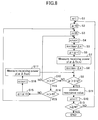
FIG. 8. FIG. 8 is a flow chart for explaining the
reactance control process of the variable reactance
control circuit 80 with respect to the passive
antenna elements.
This embodiment of the computer-readable
storage medium stores a program for causing a
computer to carry out at least the process of the
variable reactance control circuit 80. Of course,
the program stored in the computer-readable storage
medium may cause the computer to additionally carry
out the process of other parts of the array antenna
control apparatus. Any recording medium capable of
storing a program in a computer-readable manner may
be used for the computer-readable storage medium.
For example, semiconductor memory devices, magnetic
recording media, optical recording media and
magneto-optic recording media may be used as the
recording medium.
First, the variable reactance control
circuit 80 sets initial values in steps S1 through
S3 shown in FIG. 8. More particularly, the step S1
sets a number n of tries to n = 1, the step S2 sets
an nth sample α to α = 0, and the step S3 sets an
identification number m of the passive antenna
element to m = 0.
After setting the initial values, the
variable reactance control circuit 80 carries out a
step S4 and subsequent steps. The step S4
increments the identification number m of the
passive antenna element by +1 (first, the passive
antenna element 141 (#1) is selected). A step S5
pertubates a reactance xm (= x1) of the variable
reactance of the passive antenna element 141 by Δx,
where Δx denotes a small amount for changing the
voltage applied to the variable capacitance diode by
a small amount.
After changing the reactance x1 by the
small amount Δx, the variable reactance control
circuit 80 increments the nth sample α by +1 in a
step S6, and measures a received signal y (y(ΔT, n))
of the passive antenna element 141 in a step S7.
Thereafter, a step S8 changes the reactance x1 by a
small amount -Δx to return the reactance x1 to the
original reactance (x1 - Δx).
Next, the variable reactance control
circuit 80 decides whether or not the nth sample α
is greater than 512 (= 64·8) in a step S9. If the
decision result in the step S9 is NO, a step S10
decides whether or not the identification number m
of the passive antenna element is greater than "6".
If the decision result in the step S10 is NO, the
process returns to the step S4.
On the other hand, if the decision result
in the step S10 is YES, a step S14 decides whether
or not the identification number m of the passive
antenna element is greater than "8". If the
decision result in the step S14 is NO, the variable
reactance control circuit 80 increments the nth
sample α by +1 in a step S15. After the step S15, a
step S16 increments the identification number m of
the passive antenna element by +1, and a step S17
measures the received signal y.
If the decision result in the step S14 is
YES, the process returns to the step S3, and the
identification number m of the passive antenna
element is reset to 0.
Accordingly, up to the first through sixth
samples (α = 1, ..., 6), the received signal y is
measured by perturbing the reactances x1 through x6
of the passive antenna elements 141 through 146 by
Δx for each sample. At the seventh and eighth
samples (α = 7, 8), the received signal is measured
without perturbing the reactances of the passive
antenna elements.
The process advances to a next step S11
when the variable reactance control circuit 80
carries out the loop process described above at a
period of 8 samples up to the 512th sample and the
decision result in the step S9 becomes YES. The
step S11 carries out an updating process to update
the reactances x1 through x6 of the passive antenna
elements 141 through 146.
In the step S11, the received signal on
the time base (time-based received signal) at each
of the passive antenna elements 14
1 through 14
6
which is measured after the perturbation and
subjected to the Fourier transform according to the
following formula (1), so as to convert the time-based
received signal into the received signal on
the frequency base (frequency-based received signal),
where m denotes the identification number of the
passive antenna element, Γ denotes the sample number
from 1 to 512, and β denotes the subcarrier.
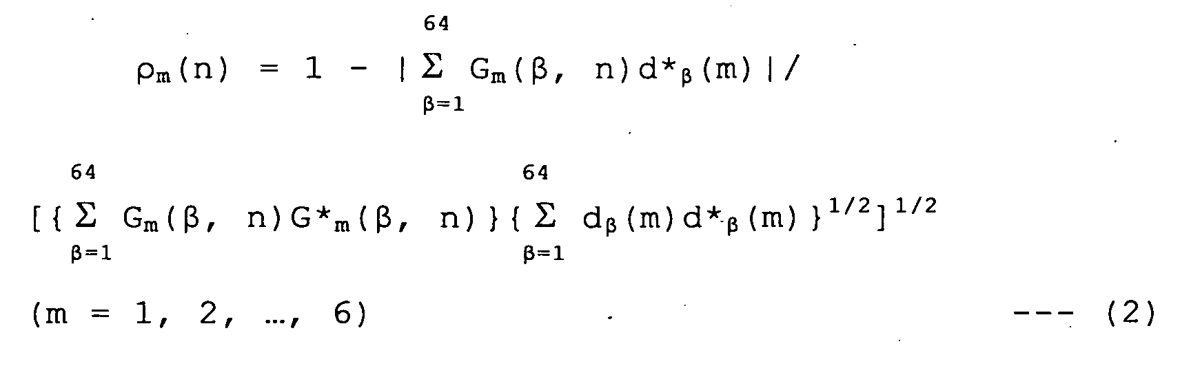
Thereafter, a correlation between the
frequency-based received signal Gm and a frequency-based
known signal is obtained from the following
formulas (2) and (3).
In the formula (2), ρm(n) indicates a
correlation coefficient for a case where the mth
passive antenna element (passive antenna element
having the identification number m = 1, ..., 6) is
perturbed, where * denotes a conjugate complex
number, and d*β(m) denotes a known signal obtained
by obtaining the complex conjugate.
In the formula (3), ρ0 indicates a
correlation coefficient for a case where the mth
passive antenna element (passive antenna element
having the identification number m = 1, ..., 6) is not
perturbed, where * denotes the conjugate complex
number, and d*β(m) denotes the known signal obtained
by obtaining the complex conjugate.
In this particular case, a long symbol of
a Physical Layer Convergence Protocol (PLCP)
preamble in conformance with the IEEE802.11a is used
as the known signal dβ(m). In other words, a signal
for transmitting control information within a frame
employed by a predetermined system or protocol, is
used to generate the known signal. The PLCP
preamble is used for a training sequence to achieve
various synchronizations including clock
synchronization when an OFDM modem receives a signal,
and is formed by 10 short symbols (amounting to 8 µs
and also called short training symbols) and 2 long
symbols (amounting to 8 µs and also called long
training symbols). The Fourier transform 70 shown
in FIG. 4 corresponds to a demodulator portion of
the OFDM modem. FIG. 9 is a diagram showing a
structure of the PLCP preamble in conformance with
the IEEE802.11a. The long training symbols are
transmitted using 52 subcarriers, and the following
known signal pattern F-26...26 is converted into a time-based
signal in an Inverse Fast Fourier Transform
(IFFT) section of the OFDM modem.
F-26...26 = [11-1-111-11-1111111-1-111-11-1111101-
1-111-11-11-1-1-1-1-111-1-11-11-11111]
The signal pattern F-26...26 is mapped to 52
subcarriers, and is formed into the transmitting
signal via a transmission power means of the OFDM
modem. The transmission power means converts a
frequency-based signal into a time-based signal. In
this particular case, "0" is inserted in the data of
the signal pattern F-26...26 so as to form 64
subcarriers, and the resulting signal pattern is
defined by Fi ( Fi ( i=1, ..., 64)). Accordingly, the
signal pattern F after the redefinition becomes as
follows.
F = [00000011-1-111-11-1111111-1-111-11-
1111101-1-111-11-11-1-1-1-1-111-1-11-11-1111100000]
The signal pattern Fi is a time-based
signal, and needs to be converted into a frequency-based
signal in order to be used for the correlation
operation (computation) on the frequency base.
Hence, a correction coefficient Ci is multiplied to
the signal pattern Fi in order to obtain the known
signal dβ (m) . For the sake of convenience, β will
be replaced by i in the following description, and
the known signal will be denoted by di(m) as may be
seen from the following formula (4).
di(m) ≡ Fi · Ci (m) , (i = 1, 2, ..., 64)
In the formula (4), Fi denotes the long
symbol of the PLCP preamble, Ci denotes the
correction coefficient, and m denotes the
identification number (1, ..., 6) of the passive
antenna element.
The correction coefficient Ci can be
obtained from the following formula (5).
Ci(m) = exp [-j2Π{i/(64 · 8)}(8-m)],
(i = 1, 2, ..., 64)
In the formula (5), m denotes the
identification number (1, ..., 6) of the passive
antenna element.
Next, a gradient vector gradρm(n) is of
the correlation coefficient is obtained as an
evaluation function, using ρm(n) and ρ0 described
above. The gradient vector gradρm(n) is defined by
the following formula (6), where Δx denotes a
predetermined shifting amount of the reactance xm(n)
of the mth passive antenna element (m =
identification number 1, ..., 6 of the passive antenna
element).
gradρm(n) = {ρm(n) - ρ0(n)} / Δx
A gradient vector gradP(n) of each of the
passive antenna elements 141 through 146 is defined
by the following formula (7), where T denotes the
transpose.
gradP (n) = [gradρ1(n) , gradρ2(n) , ..., gradρ6(n)]T
From the gradient vector gradP(n), a
reactance vector X(n) of each of the passive antenna
elements 141 through 146 can be defined by the
following formula (8), where T denotes the transpose.
X(n) = [x1(n), x2(n), ..., x6(n)]T
In this particular case, the steepest
gradient algorithm is used as the optimizing
algorithm. Accordingly, the reactance vector X
should be formed so as to minimize the evaluation
function.
An updated value X(n+1) of the reactance
vector X at the nth try using the recursive
relationship can be calculated based on the steepest
gradient algorithm, according to the following
formula (9), where µ denotes a step size with which
the convergence speed is controlled (the rate of
updating the weighting is controlled).
X(n+1) = X(n) - µgradP (n)
In other words, in this embodiment, ρm(n)
and ρ0(n) of the mth passive antenna element (m =
identification number 1, ..., 6 of the passive antenna
element) for the nth try are obtained, and mutual
correlation values are compared. If ρm(n) is higher
than ρ0(n), the reactance vector which minimizes the
evaluation function is obtained by operating the
reactance of the mth passive antenna element in a
positive direction. On the other hand, if ρ0(n) is
higher than ρm(n), the reactance vector which
minimizes the evaluation function is obtained by
operating the reactance of the mth passive antenna
element in a reverse direction, that is, in a
negative direction. By successively carrying out
the updating process with respect to the reactance
vector in this manner, it is possible to optimize
the reactances x1 through x6 of all of the passive
antenna elements 141 through 146.
After updating the reactances of all of
the passive antenna elements 141 through 146
according to the formula (9), the variable reactance
control circuit 80 increments n by +1 in a step S12.
Then, a step S13 decides whether or not n is greater
than or equal to a predetermined repetition number N.
If n has not reached the predetermined repetition
number N and the decision result in the step S13 is
NO, the process returns to the step S2. On the
other hand, if the decision result in the step S13
is YES, the reactance control process of the
variable reactance control circuit 80 with respect
to the passive antenna elements ends.
As described above, the reactance control
process of this embodiment samples the OFDM symbol
by carrying out an 8-times over-sampling to obtain
512 samples. Thus, the perturbation time (or
duration) per passive antenna element is shortened
from 3.2 µs to 6.25 ns (= 3.2 µs/512). Consequently,
it is possible to update the reactance of 6 passive
antenna elements within the time of 1 symbol, and
the convergence speed of the optimizing algorithm
can be greatly increased compared to the
conventional case.
In the embodiment described above, the
correlation coefficient ρm(n) is used as the
evaluation function of the steepest gradient
algorithm. However, the evaluation function is not
limited to such, and the present invention may
employ other functions such as an output power
reference which is used as a reference for an output
power of the array antenna. In this case, the
output power of the array antenna is defined as the
evaluation function, and a steering vector which
indicates direction of arrival information of the
desired wave is used in addition to the received
signal and the output of the antenna array.
Next, a description will be given of a
simulation result which is obtained by using this
embodiment of the array antenna control apparatus.
The simulation was carried out under the following
simulation conditions, where λ denotes the
wavelength and UCA denotes the Uniform Circular
Array. FIGS. 10 and 11 show the simulation results
which do not take noise into consideration, and FIGS.
12 and 13 show the simulation results for a case
where the Signal-to-Noise Ratio (SNR) is 20 [dB].
Modulation Technique: OFDM Arriving Wave Environment: 1 Desired Wave (0°) + 1
Interference Wave (100°) Initial SIR: 0 [dB] Angular Spread: None Frame Format: In Conformance With IEEE802.11a
Norm: MMSE Optimizing Algorithm: Steepest Gradient Theory µ: Step Size No. of Passive Antenna Elements: 6 Pitch of Antenna Elements: λ/4 [m] Antenna Arrangement: UCA (Circularly Arranged) Sampling: 8-Times Over-Sampling Perturbation Time of Variable Reactance: 6.25 [ns]
(1/512 symbols) Quantization: Ideal Frequency Offset of Transmission & Reception: None
FIG. 10 is a diagram showing a convergence
characteristic of the evaluation function ρm(n) with
respect to the number of tries, n, in a state where
no noise exists. In FIG. 10, the ordinate indicates
the evaluation function ρm(n), and the abscissa
indicates the number n of tries in 1 long training
symbol time (4 µs). According to this simulation
result, the convergence of the evaluation function
ρm(n) is observed by varying the step size µ. In
FIG. 10, the smaller the value of the evaluation
function ρm(n), the faster the convergence speed of
the optimizing algorithm. As shown in FIG. 10, the
optimizing algorithm converges within several
symbols depending on the step size µ. For example,
the convergence speed of the optimizing algorithm is
the fastest when µ = 1000.
FIG. 11 is a diagram showing a horizontal
directivity pattern of a state shown in FIG. 14
where a desired wave signal S (1 wave) arrives from
a 0° direction and an interference wave I (1 wave)
arrives from a 100° direction, in a state where no
noise exists. FIG. 14 is a diagram showing a model
of signal sources used in obtaining the simulation
results for this embodiment of the array antenna
control apparatus. In FIG. 11, the ordinate
indicates a relative gain [dB], and the abscissa
indicates the Direction Of Arrival (DOA), that is,
the direction [deg] of the incoming (arriving) wave.
As shown in FIG. 11, this embodiment of the array
antenna control apparatus can adaptively control the
array antenna so that the main directional beam is
directed towards the desired wave and the null
antenna directivity is directed towards the
interference wave to null out the interference wave.
FIG. 12 is a diagram showing a convergence
characteristic of the evaluation function ρm(n) with
respect to the number of tries, n, in a state where
the SNR is 20 [dB]. In FIG. 12, the ordinate
indicates the evaluation function ρm(n), and the
abscissa indicates the number n of tries in 1 long
training symbol time (4 µs). According to this
simulation result, the convergence of the evaluation
function ρm(n) is observed by varying the step size
µ, similarly to FIG. 10. In FIG. 12, the optimizing
algorithm appears as if it converges within several
symbols when the step size µ is large, but the
convergence state is unstable due to the effects of
the noise. Accordingly, the step size µ should be
selected so that the effects of the noise becomes
negligible. For example, the convergence speed of
the optimizing algorithm is the fastest when µ =
1000.
FIG. 13 is a diagram showing a horizontal
directivity pattern of the state shown in FIG. 14
where the desired wave signal S (1 wave) arrives
from the 0° direction and the interference wave I (1
wave) arrives from the 100° direction, in the state
where the SNR is 20 [dB]. In FIG. 13, the ordinate
indicates a relative gain [dB], and the abscissa
indicates the Direction Of Arrival (DOA), that is,
the direction [deg] of the incoming (arriving) wave.
As shown in FIG. 13, this embodiment of the array
antenna control apparatus can adaptively control the
array antenna so that the main directional beam is
directed towards the desired wave and the null
antenna directivity is directed towards the
interference wave to null out the interference wave,
even in an environment in which the noise exists.
As described above, according to the
conventional method, the weighting of one passive
antenna element is updated by use of one symbol, and
a number of symbols corresponding to the number of
antenna elements were required to update the
weighting of all of the antenna elements. But in
this embodiment, it is possible to update the
weighting of six passive antenna elements by use of
one symbol, thereby increasing the convergence speed
of the optimizing algorithm.
In addition, by providing the variable
reactance control circuit 80, which controls the
weighting of the passive antenna elements, in a
radio frequency (RF) processing part which includes
the RF F/E section 42, it is possible to reduce the
size and weight of the circuit and also reduce the
power consumption and the cost of the circuit.
Furthermore, the reactance control process
(updating process) with respect to the passive
antenna elements may be realized by software
operation, and in this case, it is possible to
improve the maintainability. When realizing the
reactance control process by software, the variable
reactance control circuit 80 may be formed by a
computer, that is, a processor such as a CPU.
In the embodiment described above, the
time-based data obtained after perturbation of each
of the passive antenna elements 141 through 146 is
converted into the frequency-based data, and the
correlation of the frequency-based data and a
frequency-based known signal dβ(m) is obtained.
However, the present invention is not limited to
such an embodiment, and it is possible to obtain
other correlations. For example, a time-based known
signal may be prepared, and the correlation of this
time-based known signal and the time-based data
obtained after the perturbation of each of the
passive antenna elements 141 through 146 may be
obtained.
According to the OFDM, the guard interval
is added on the time base, and thus, the delayed
wave within the guard interval can be received in a
normal manner. The incoming delayed wave arriving
within the guard interval is not necessarily one
wave. Hence, the known signal may be generated by
taking into consideration all incoming delayed waves
arriving within the guard interval. In this case,
if is possible to provide an impulse response
estimating (or measuring) means to estimate (or
measure) the impulse response to the propagation
path, and to use this means to carry out a
convolution with respect to the estimated (or
measured) impulse response of the propagation path
and the time-based known signal which is prepared in
advance for a Fourier transform. The signal
obtained by the Fourier transform may be used as the
frequency-based known signal. As a result, it is
possible to improve both the SNR of the OFDM signal
and the reception characteristics.
The impulse response, which describes the
instantaneous characteristics of the time-varying
transmission path in the time-domain, is used to
generate the known signal in the above described
case. However, the known signal may be generated by
other means, such as by use of a delay profile which
statistically describes the instantaneous
characteristics of the transmission path or, by use
of a transfer function which describes the
instantaneous characteristics of the transmission
path in the frequency-domain.
In other words, the array antenna control
apparatus may include a profile obtaining unit to
obtain a delay profile statistically describing
instantaneous characteristics of a transmission path,
and a reference signal generator to generate a
frequency-based reference signal which is described
in a frequency-domain, by performing a Fourier
transform on a time-based reference signal which is
described in a time-domain and generated based on
the delay profile. An adjusting part of the
variable reactance control circuit 80 may define as
the evaluation function a correlation coefficient
which is obtained from a correlation of the
frequency-based digital signal which is output from
a base converter (which converts the time-based
digital signal output from the A/D converter 52 into
the frequency-based digital signal) and the
frequency-based reference signal.
Alternatively, the array antenna control
apparatus may include a profile obtaining unit to
obtain a delay profile statistically describing
instantaneous characteristics of a transmission path,
and a reference signal generator to generate a time-based
reference signal which is described in a time-domain,
based on the delay profile. An adjusting
part of the control unit may define as the
evaluation function a correlation coefficient which
is obtained from a correlation of a time-based
digital signal which is output from the A/D
converter 52 and the time-based reference signal.
In addition, the array antenna control
apparatus may include a transfer function obtaining
unit to obtain a transfer function describing
instantaneous characteristics of a transmission path
in a frequency-domain, and a reference signal
generator to generate a frequency-based reference
signal, based on the transfer function. An
adjusting part of the variable reactance control
circuit 80 may define as the evaluation function a
correlation coefficient which is obtained from a
correlation of the frequency-based digital signal
which is output from a base converter (which
converts the time-based digital signal output from
the A/D converter 52 into the frequency-based
digital signal) and the frequency-based reference
signal.
Alternatively, the array antenna control
apparatus may include a transfer function obtaining
unit to obtain a transfer function describing
instantaneous characteristics of a transmission path
in a frequency-domain, and a reference signal
generator to generate a time-based reference signal
which is described in a time-domain, by performing a
Fourier transform on a frequency-based reference
signal which is described in a frequency-domain and
generated based on the transfer function. An
adjusting part of the variable reactance control
circuit 80 may define as the evaluation function a
correlation coefficient which is obtained from a
correlation of the time-based digital signal which
is output from the A/D converter 52 and the time-based
reference signal.
In the embodiment described above, the
known signal is generated by taking into
consideration the 64 subcarriers. However, as
described above, no all of the 64 subcarriers are
used for the data transmission. Since the wave
having a component in the virtual subcarrier which
is not used for the data transmission is regarded as
the interference wave, the effect of suppressing the
interference wave can be improved by generating the
known signal by taking into account the virtual
subcarrier component. Therefore, the known signal
may be generated by obtaining the correlation of the
frequency-based known signal and the frequency-based
signal after the perturbation of each of the passive
antenna elements 141 through 146 and defining the
correlation value as a portion of the evaluation
function, and defining the subcarrier component
which actually does not transmit data as the
evaluation function.
Moreover, the impulse response to the
propagation path may be estimated (or measured) by
the impulse response estimating (or measuring) means
described above, and the convolution may be carried
out with respect to the estimated (or measured)
impulse response of the propagation path and the
time-based known signal which is prepared in advance,
so as to use the time-based signal after the
convolution as the known signal.
The known signal of the described
embodiment is based on the PLCP preamble in
conformance with the IEEE802.11a. But the known
signal changes depending on the system, such as the
HiSWAN, CSMA and HIPERLAN/2 which are broadband
mobile access systems.
The present invention is applied to the
array antenna which is formed by the active antenna
element and the passive antenna elements, in the
embodiment described above. However, it is of
course possible to apply the present invention to
array antennas having other structures, such as an
adaptive array antenna which adjusts the phase and
the amplitude of the incoming signals arriving at
the plurality of antenna elements as antenna weights,
and a phased array antenna which adjusts the amount
of phase shift by a phase shifter.
The array antenna control apparatus
described heretofore is applied to one array antenna
part. However, the present invention is not limited
to the application to the single array antenna part,
and the present invention may be similarly applied
to a case where a plurality of array antenna parts
are arranged at predetermined distances and the
array antenna parts are selected so as to form a
space diversity structure, as in the case of the
modifications described hereunder.
FIG. 15 is a diagram for explaining a
weighting coefficient updating process which is
carried out by selecting a diversity branch.
In FIG. 15, a plurality of array antenna
parts having the structure shown in FIG. 4 are
provided to form diversity branches (branches 1
through n) 151 through 15N· The array antenna part
of each of the diversity branches 151 through 15N
includes antenna elements similar to those shown in
FIG. 4 (that is, one active antenna element and a
plurality of passive antenna elements), a weighting
circuit part (variable reactance circuit part), and
a variable reactance control circuit which
calculates the weighting coefficients to be supplied
to the weighting circuit part. The array antenna
part may further include a radio frequency front end
(RF F/E) section to receive outputs of the passive
antenna elements, an analog-to-digital (A/D)
converter and a Fourier transform section. In FIG.
15, a branch selector 90 is provided to select a
branch outputting a largest signal level. The
diversity branches 151 through 15N are separated by
a sufficient distance so that the fading correlation
becomes sufficiently small.
A radio signal transmitted from the OFDM
transmitter of the other (transmitting) end is
received by the diversity branches 151 through 15N,
and the branch which outputs the largest signal
level is selected. The updating process to update
the weighting coefficients is carried out with
respect to the selected branch.
In this case, only the branch which
outputs the received signal having the highest
quality is selected, of the plurality of diversity
branches, and the weighting coefficient updating
process is carried out only with respect to the
selected branch. In other words, the weighting
coefficient updating process is a selective
combining type. However, the weighting coefficient
updating process may be an equi-gain combing type
which makes the phases of the signals output from
each of the diversity branches the same and adds the
signals for use in the weighting coefficient
updating process.
FIG. 16 is a diagram for explaining a
weighting coefficient updating process which is
carried out by combining the diversity branches.
In FIG. 16, signals from each of diversity
branches (array antenna parts 1 through N) 161
through 16N are subjected to phase detection in a
plurality of phase change detectors (only two phase
change detectors 101 and 103 shown in FIG. 16), and
phase errors of the signals are adjusted by a
plurality of phase change compensators (only two
phase change compensators 102 and 104 shown in FIG.
16) so that the phases of the signals become the
same. The diversity branches 161 through 16N may
have a structure similar to that of the diversity
branches 151 through 15N shown in FIG. 15. The
signals output from the diversity branches 161
through 16N and adjusted to have the same phase are
added in a diversity combiner 110. An output signal
of the diversity combiner 110 is supplied to the
variable reactance control circuit of each of the
diversity branches 161 through 16N to control the
weighting coefficient updating process in each of
the diversity branches 161 through 16N. In this
case, since the phases of the signals output from
each of the diversity branches are adjusted to the
same phase and the unadjusted amplitudes are then
added, the reception characteristic can further be
improved compared to the selective combining type
described above.
The phase change detectors 101 and 103 and
the phase change compensators 102 and 104 may carry
out the processes digitally in FIG. 16. On the
other hand, the phase change detectors 101 and 103
and the phase change compensators 102 and 104 may be
provided within the radio frequency (RF) processing
part which includes the RF F/E section 42, and in
this case, the phase change detectors 101 and 103
and the phase change compensators 102 and 104 may
carry out the processes in analog form.
By combining the array antenna control
apparatus of the present invention with the space
diversity structure, it is possible to updating the
weighting coefficients at a high speed while
simultaneously improving the transmission
characteristics.
According to these modifications, the
array antenna control apparatus of the present
invention is applied to the space diversity
structure. However, the present invention is of
course similarly applicable to other diversity
structures such as the polarization diversity
structure which uses a plurality of reception
antennas and the angular diversity structure.
Of course, the phase and amplitude of the
incoming signal arriving at the antenna element may
be adjusted so as to minimize or maximize the
evaluation function.
Therefore, according to the array antenna
control apparatus of the present invention, an 8-times
over-sampling is performed with respect to the
received signal so as to obtain 512 samples within 1
symbol time, and further, the passive antenna
elements are perturbed for every sample to
adaptively control the weighting coefficients of the
passive antenna elements. Hence, the weighting
coefficients of the passive antenna elements can be
updated by 1 symbol, thereby enabling the
convergence speed of the optimizing algorithm to be
increased and the interference wave to be suppressed.
In addition, it is also possible to reduce both the
power consumption and the size of the array antenna
control apparatus.
Further, the present invention is not
limited to these embodiments, but various variations
and modifications may be made without departing from
the scope of the present invention.