EP1443583A2 - Fuel cell stack and fuel cell module - Google Patents
Fuel cell stack and fuel cell module Download PDFInfo
- Publication number
- EP1443583A2 EP1443583A2 EP03255039A EP03255039A EP1443583A2 EP 1443583 A2 EP1443583 A2 EP 1443583A2 EP 03255039 A EP03255039 A EP 03255039A EP 03255039 A EP03255039 A EP 03255039A EP 1443583 A2 EP1443583 A2 EP 1443583A2
- Authority
- EP
- European Patent Office
- Prior art keywords
- fuel cell
- fuel
- interconnect
- interconnects
- anode
- Prior art date
- Legal status (The legal status is an assumption and is not a legal conclusion. Google has not performed a legal analysis and makes no representation as to the accuracy of the status listed.)
- Withdrawn
Links
Images


Classifications
-
- H—ELECTRICITY
- H01—ELECTRIC ELEMENTS
- H01M—PROCESSES OR MEANS, e.g. BATTERIES, FOR THE DIRECT CONVERSION OF CHEMICAL ENERGY INTO ELECTRICAL ENERGY
- H01M8/00—Fuel cells; Manufacture thereof
- H01M8/02—Details
- H01M8/0202—Collectors; Separators, e.g. bipolar separators; Interconnectors
- H01M8/0258—Collectors; Separators, e.g. bipolar separators; Interconnectors characterised by the configuration of channels, e.g. by the flow field of the reactant or coolant
-
- H—ELECTRICITY
- H01—ELECTRIC ELEMENTS
- H01M—PROCESSES OR MEANS, e.g. BATTERIES, FOR THE DIRECT CONVERSION OF CHEMICAL ENERGY INTO ELECTRICAL ENERGY
- H01M8/00—Fuel cells; Manufacture thereof
- H01M8/02—Details
- H01M8/0271—Sealing or supporting means around electrodes, matrices or membranes
-
- H—ELECTRICITY
- H01—ELECTRIC ELEMENTS
- H01M—PROCESSES OR MEANS, e.g. BATTERIES, FOR THE DIRECT CONVERSION OF CHEMICAL ENERGY INTO ELECTRICAL ENERGY
- H01M8/00—Fuel cells; Manufacture thereof
- H01M8/24—Grouping of fuel cells, e.g. stacking of fuel cells
-
- H—ELECTRICITY
- H01—ELECTRIC ELEMENTS
- H01M—PROCESSES OR MEANS, e.g. BATTERIES, FOR THE DIRECT CONVERSION OF CHEMICAL ENERGY INTO ELECTRICAL ENERGY
- H01M8/00—Fuel cells; Manufacture thereof
- H01M8/24—Grouping of fuel cells, e.g. stacking of fuel cells
- H01M8/241—Grouping of fuel cells, e.g. stacking of fuel cells with solid or matrix-supported electrolytes
- H01M8/2425—High-temperature cells with solid electrolytes
- H01M8/2432—Grouping of unit cells of planar configuration
-
- H—ELECTRICITY
- H01—ELECTRIC ELEMENTS
- H01M—PROCESSES OR MEANS, e.g. BATTERIES, FOR THE DIRECT CONVERSION OF CHEMICAL ENERGY INTO ELECTRICAL ENERGY
- H01M8/00—Fuel cells; Manufacture thereof
- H01M8/24—Grouping of fuel cells, e.g. stacking of fuel cells
- H01M8/2465—Details of groupings of fuel cells
- H01M8/2483—Details of groupings of fuel cells characterised by internal manifolds
-
- H—ELECTRICITY
- H01—ELECTRIC ELEMENTS
- H01M—PROCESSES OR MEANS, e.g. BATTERIES, FOR THE DIRECT CONVERSION OF CHEMICAL ENERGY INTO ELECTRICAL ENERGY
- H01M8/00—Fuel cells; Manufacture thereof
- H01M8/24—Grouping of fuel cells, e.g. stacking of fuel cells
- H01M8/2465—Details of groupings of fuel cells
- H01M8/2484—Details of groupings of fuel cells characterised by external manifolds
- H01M8/2485—Arrangements for sealing external manifolds; Arrangements for mounting external manifolds around a stack
-
- H—ELECTRICITY
- H01—ELECTRIC ELEMENTS
- H01M—PROCESSES OR MEANS, e.g. BATTERIES, FOR THE DIRECT CONVERSION OF CHEMICAL ENERGY INTO ELECTRICAL ENERGY
- H01M8/00—Fuel cells; Manufacture thereof
- H01M8/24—Grouping of fuel cells, e.g. stacking of fuel cells
- H01M8/249—Grouping of fuel cells, e.g. stacking of fuel cells comprising two or more groupings of fuel cells, e.g. modular assemblies
-
- Y—GENERAL TAGGING OF NEW TECHNOLOGICAL DEVELOPMENTS; GENERAL TAGGING OF CROSS-SECTIONAL TECHNOLOGIES SPANNING OVER SEVERAL SECTIONS OF THE IPC; TECHNICAL SUBJECTS COVERED BY FORMER USPC CROSS-REFERENCE ART COLLECTIONS [XRACs] AND DIGESTS
- Y02—TECHNOLOGIES OR APPLICATIONS FOR MITIGATION OR ADAPTATION AGAINST CLIMATE CHANGE
- Y02E—REDUCTION OF GREENHOUSE GAS [GHG] EMISSIONS, RELATED TO ENERGY GENERATION, TRANSMISSION OR DISTRIBUTION
- Y02E60/00—Enabling technologies; Technologies with a potential or indirect contribution to GHG emissions mitigation
- Y02E60/30—Hydrogen technology
- Y02E60/50—Fuel cells
Definitions
- the invention relates generally to fuel cell stacks and modules for power generation, and more particularly, to fuel cell stacks and modules with segregated reactant streams.
- Fuel cells for example solid oxide fuel cells (SOFCs) are energy conversion devices that produce electricity by electrochemically combining a fuel and an oxidant across an ionic conducting layer.
- the fuel cell operating temperatures depend on the material forming the ionic conducting layer.
- power generation systems incorporating high-temperature fuel cells have the potential for higher efficiencies and power outputs.
- Exemplary high-temperature fuel cells have operating temperatures above about 600° C, and exemplary SOFCs operate in a range of about 800 to about 1000 degrees Celsius.
- a typical fuel cell operates at a potential of less than about one (1) Volt.
- a number of individual fuel cells are integrated into a larger component. Separation of the oxidant and fuel streams is desirable for multistaging and the use of reactant products by other devices in a power generation system.
- a large number of elastomer seals in compression may be used to separate the two reactants. Elastomer seals cannot withstand the operating temperatures of high-temperature fuel cells, and consequently other materials, such as glass ceramics, must be used to form the seals.
- seal performance remains problematic for high temperature fuel cells, in particular for designs requiring sealing of cell edges or corners or for other joint designs that require maintaining a gap of a certain size during thermal expansion and contraction cycles.
- a fuel cell stack includes a number of interconnects.
- Each interconnect defines at least two openings and includes at least one flow field for flowing a reagent.
- Each opening defines a respective fuel manifold, including at least one intake fuel manifold and at least one exhaust fuel manifold.
- the fuel cell stack further includes at least one fuel cell unit comprising an anode, a cathode, and an electrolyte disposed between the anode and the cathode.
- the anode is positioned adjacent to a respective one of the interconnects and is configured to be in both electrical connection and fluid communication with the respective interconnect.
- the flow field of the respective interconnect is configured to guide a fuel flow from the intake fuel manifold to the fuel exhaust manifold.
- the cathode is positioned adjacent to another respective one of the interconnects and is configured to be in both electrical connection and fluid communication with this interconnect.
- the flow field of this interconnect is configured to guide an oxidant flow across this interconnect.
- the fuel cell stack further includes a perimeter isolation seal disposed around the respective one of the interconnects adjacent to the anode. The perimeter isolation seal is disposed on a side of the interconnect facing the anode and is configured to seal the electrolyte to the interconnect.
- the fuel cell stack further includes at least two interior isolation seals disposed on the respective one of the interconnects adjacent to the cathode and on a side of the respective interconnect facing the cathode.
- One interior isolation seal surrounds each of the openings and is configured to seal the electrolyte to the respective interconnect.
- a fuel cell module is also disclosed.
- the fuel cell module includes a vessel having an inlet and an outlet, which are configured to receive and exhaust an oxidant, respectively.
- the fuel cell module also includes at least three fuel cell stacks arranged in a ring within the vessel. The fuel cell stacks separate an inner and an outer volume of the vessel, which volumes are in fluid communication through the fuel cell stacks. At least one of the fuel cell stacks has a fuel inlet, and at least one of the fuel cell stacks has a fuel outlet for receiving and exhausting a fuel flow, respectively.
- Each fuel cell stack includes at least two fuel manifolds, for receiving and exhausting the fuel flow, and at least one planar, high-temperature fuel cell unit comprising an anode, a cathode, and an electrolyte disposed between the anode and the cathode.
- Each fuel cell stack further includes a number of compressive seals for segregating the cathode and the fuel flow through the fuel manifolds and for segregating the anode and the oxidant.
- the fuel cell module also includes a number of electrical connections between the fuel cell stacks for electrically connecting each fuel cell stack to at least one other fuel cell stack.
- fuel cell stack 10 includes a number of interconnects 22, each interconnect 22 defining at least two openings 24 in the plane of the interconnect 22, with each opening 24 defining a respective fuel manifold 25.
- the fuel manifolds 25 include at least one intake fuel manifold 251 and at least one exhaust fuel manifold 252.
- intake and exhaust manifolds 251, 252 may also be parallel in the same direction or perpendicular.
- each interconnect defines four, symmetrically arranged openings 24, which in turn define four fuel manifolds 25, for symmetric distribution of fuel within fuel cell stack 10.
- Each interconnect 22 also includes at least one flow field 34 for flowing a reagent, such as an oxidant or a fuel, across interconnect 22.
- a reagent such as an oxidant or a fuel
- Exemplary flow fields 34 are formed from metals that possess the requisite electrical conductivity, resist oxidation, maintain mechanical strength and are chemically stable under the operating conditions of the fuel cell. For example, for operating temperatures below 750-800 °C, the flow fields 34 could be stamped from metals compositions based on ferritic, stainless steels. Further, the exemplary flow fields 34 are fit into a channel in interconnect 22 or form an integral part of interconnect 22.
- Fuel cell stack 10 also includes at least one fuel cell unit 20 comprising an anode 26, a cathode 28, and an electrolyte 27 disposed between the anode and the cathode.
- Exemplary electrolytes 27 are impermeable with respect to both the fuel and the oxidant.
- exemplary electrolytes 27 are solid electrolytes 27, such as ion-conducting ceramic or polymer membranes.
- One exemplary planar fuel cell unit 20 is a solid oxide fuel cell 20, with an oxygen-ion conducting solid electrolyte, such as yttria stabilized zirconia (YSZ), ceria-doped zirconia, or lanthanum strontium gallium manganate (LSGM).
- an oxygen-ion conducting solid electrolyte such as yttria stabilized zirconia (YSZ), ceria-doped zirconia, or lanthanum strontium gallium manganate (LSGM).
- the anode 26 is positioned adjacent to a respective interconnect 22 and is configured to be in both electrical connection and fluid communication with interconnect 22.
- flow field 34 supplies both the electrical connection and fluid communication.
- the flow field 34 of this respective interconnect 22 is configured to guide a fuel flow from at least one intake fuel manifold 251 to at least one fuel exhaust manifold 252, over the surface of anode 26.
- the cathode 28 is positioned adjacent to a respective interconnect 22 and is configured to be in both electrical connection and fluid communication with interconnect 22. As indicated in Figure 1, the flow field 34 of this respective interconnect 22 provides the electrical connection to cathode 28 and is configured to guide an oxidant flow across the interconnect 22 and over the surface of cathode 28.
- One exemplary oxidant is air.
- fuel cell stack 10 includes a perimeter isolation seal 44 disposed around the interconnect 22 that is adjacent to anode 26.
- perimeter isolation seal 44 also extends inward between openings 24.
- the perimeter isolation seal 44 is disposed on a side of the interconnect 22 that faces the anode 26 and is configured to seal the electrolyte 27 to the interconnect 22.
- perimeter isolation seal 44 shields anode 26 from the oxidant surrounding planar fuel cell unit 20.
- fuel cell stack 10 also includes at least two interior isolation seals 45 disposed on the interconnect 22 adjacent to the cathode 28 and on a side of the interconnect 22 facing the cathode 28, as indicated in Figure 1. As shown, one interior isolation seal 45 surrounds each opening 24 and seals the electrolyte 27 to the interconnect 22.
- seals 44, 45 are compressive, as indicated in Figure 1, as compared to the edge seals (not shown) found on typical planar stack designs (not shown).
- compressive it is meant that seals 44, 45 deform when placed in compression, either from the weight of the stack 10 or a mechanical means, such as tie bolts, to provide a better seal.
- fuel cell stack 10 includes a number of planar fuel cell units 20 arranged in a vertical stack, according to a particular embodiment.
- the particular configuration of three (3) planar fuel cell units 20 shown in Figure 2 is for illustrative purposes only, and the specific number of planar fuel cell units 20 included in the stack 10 will vary depending on the power requirements of the stack 10.
- each of the two pairs of adjacent planar fuel cell units 20 shares an interconnect 22, with the interconnect 22 being adjacent and electrically connected to and in fluid communication with the anode 26 of one of the adjacent planar fuel cell units 20 and with the cathode 28 of the other adjacent planar fuel cell unit 20.
- interconnect 22 being adjacent and electrically connected to and in fluid communication with the anode 26 of one of the adjacent planar fuel cell units 20 and with the cathode 28 of the other adjacent planar fuel cell unit 20.
- each of the interconnects 22, which is shared by the adjacent planar fuel cell units 20, includes a flow field 34 on each side of the interconnect 22, for electrical connection and to provide fluid communication for the adjacent anode 26 and cathode 28 of the neighboring planar fuel cell units 20.
- each planar fuel cell unit 20 is polygonal, as shown for example in Figure 1.
- polygonal configurations of fuel cell units 20 are relatively easy to manufacture and permit the minimal yet robust sealing arrangements discussed above.
- corner stack seal 43 shown for example in Figures 3 and 4 need not be completely hermetic but must only provide sufficient resistance to the reactant flow through the stack 10 to maintain the separation of inlet and outlet oxidant flows.
- corner stack seals 43 may be "leaky seals,” that is non-hermetic seals designed with a higher flow resistance that that of fuel cell stacks 10, such that the majority of the fuel and oxidant flows through the fuel cell stacks, rather than through corner stack seal 43.
- Exemplary leaky seals are formed from a compressible cloth or a dense foam.
- the polygonal components may be stacked and arranged to form fuel cell stacks 10 prior to insertion in a vessel 62.
- the fuel cell stacks 10 are self-aligning when stacked together due to the angles provided by the polygonal shape.
- each planar fuel cell unit 20 is rectangular.
- each planar fuel cell unit 20 is hexagonal.
- each interconnect 22 defines four openings 24, which are arranged in two pairs 50 positioned on two opposing ends 52 of the interconnect 22, each pair defining an intake fuel manifold 251 and an exhaust fuel manifold 252, as indicated by arrows in Figure 1.
- this configuration of openings 24 facilitates the symmetric distribution of fuel across the planar. fuel cell unit 20.
- the planar fuel cell unit 20 illustrated in Figure 1 is a polygonal solid oxide fuel cell 20.
- the fuel cell stack 10 embodiment shown in Figure 2 further includes a top end plate 12, which is disposed above an upper one of the planar fuel cell units 20, and a bottom end plate 14, which is disposed below a lower one of the planar fuel cell units 20.
- End plates 12, 14 are adapted for current collection, and exemplary top and bottom end plates 12, 14 are formed of ferritic stainless steel.
- end plates 12, 14 cap the fuel cell stack 10, preventing the fuel and oxidant from bypassing the fuel cell stack 10.
- the electric potential between the two end plates 12, 14 is the total voltage of the fuel cell stack 10 and equals the sum of the voltages of the individual cells 20.
- the electrolyte 27 is impermeable to the reactants (hereinafter “substantially solid") and is deposited onto anode 26 and the respective one of the interconnects 22, for example by plasma spray, physical vapor deposition, or chemical vapor deposition techniques.
- the perimeter isolation seal 44 comprises the electrolyte 27 and is formed by the deposition of the electrolyte 27 on the respective interconnect 22.
- An exemplary perimeter isolation seal 44 comprising electrolyte 27 is shown in Figure 9.
- the electrolyte is thicker in an inactive area for sealing, than in the active area.
- the electrolyte 27 can be made thicker, for example by masking during the deposition process prior to assembly of fuel cell unit 20.
- this perimeter isolation seal 44 formed by direct bonding of the electrolyte 27 to the respective interconnect 22, is substantially planar and thus does not require maintenance of a certain gap size.
- the substantially solid electrolyte 27 may also be bonded to the anode 26, for example by sintering, with an intermediary layer (not shown) deposited to enhance the bond between the interconnect 22 and the electrolyte 27.
- Other exemplary seals 44, 45 comprise glass, glass ceramics, metal, metal brazes, or combinations thereof deposited on the respective interconnect 22, for example, using one the deposition techniques listed above, to seal the electrolyte 27 to the respective interconnect 22.
- these seals. 44, 45 are also substantially planar, thus obviating maintenance of a certain gap size.
- a fuel cell module 60 is described with respect to Figures 3, 4, 5, 7 and 8. As shown in Figures 3 and 7, fuel cell module 60 includes a vessel 62 having an inlet 68 and an outlet 70, which are configured to respectively receive and exhaust an oxidant, for example air. Fuel cell module 60 further includes at least three fuel cell stacks 10 arranged in a ring within vessel 62. As shown in Figure 4, the fuel cell stacks 10 separate an inner and an outer volume 64, 66 of vessel 62, which are in fluid communication through the fuel cell stacks 10. At least one fuel cell stack 10 has a fuel inlet 72, and at least one fuel cell stack 10 has a fuel outlet 74, as indicated in top view in Figure 6, for receiving and exhausting a fuel flow, respectively.
- Each fuel cell stack 10 includes at least two fuel manifolds 25, for receiving and exhausting the fuel flow, and further includes at least one planar, high-temperature fuel cell unit 20.
- high-temperature fuel cell refers to a fuel cell having an operating temperature of at least about 600 degrees Celsius, for example a molten carbonate or solid oxide fuel cell.
- planar, high-temperature fuel cell unit 20 includes an anode 26, a cathode 28, and an electrolyte 27 disposed between the anode 26 and the cathode 28.
- Each fuel cell stack 10 further includes a number of seals 44, 45 for segregating the cathode 28 and the fuel flow through fuel manifolds 25 and for segregating the anode 26 and the oxidant.
- seals 44, 45 are compressive, as indicated in Figure 1, as compared to the edge seals (not shown) found on typical planar stack designs (not shown).
- Fuel cell module 60 further includes a number of electrical connections 54 between fuel cell stacks 10 for electrically connecting each fuel cell stack 10 to at least one other fuel cell stack 10.
- the electrical connections 54 are provided by the interconnects 22. Jumper wires 54 could also be used to provide the electrical connections 54 between fuel cell stacks 10, as indicated in Figure 5.
- Fuel cell stacks 10 may be connected in many ways, with different voltages and redundancies. For example, if the stacks 10 are electrically connected pairwise in parallel, and the two pairs of stacks 10 are electrically connected in series in the fuel cell module 60 of Figure 3, then fuel cell module 60 provides a voltage equal to the sum of the voltages across a pair of connected stacks 10, with a twofold redundancy, due to the parallel current path. Similarly, if all four stacks 10 are connected in parallel in the fuel cell module 60 of Figure 3, then the voltage supplied by fuel cell module 60 is limited to the voltage of a single stack 10, but the redundancy is four-fold.
- vessel 62 is a pressure vessel 62.
- pressure vessel 62 is configured to force the oxidant through fuel cell stacks 10, such that the oxidant contacts the porous cathodes 28.
- Specific pressures vary with power generation applications.
- one exemplary pressure vessel 62 is configured to operate in a range of about three (3) to about ten (10) atmospheres.
- use of a pressure vessel 62 provides higher pressure reactants, to achieve higher fuel cell 20 voltages.
- inlet 68 is configured to receive the oxidant into the inner volume 64 of vessel 62
- outlet 70 is configured to exhaust the oxidant from the outer volume 66 of vessel 62.
- each planar, high-temperature fuel cell unit 20 is configured to convey the oxidant from the inner volume 64 to the outer volume 66 of the vessel 62.
- One benefit of the configuration shown in Figure 3 is that fuel in the pipes between the stacks 10 is heated by the hot exhaust oxidant flow.
- the inlet 68 is configured to receive the oxidant into the outer volume 66 of vessel 62
- the outlet 70 is configured to exhaust the oxidant from the inner volume 64 of vessel 62.
- each planar, high-temperature fuel cell unit 20 is configured to convey the oxidant from the outer volume 66 to the inner volume 64 of the vessel 62. This latter embodiment cools the stacks 10 with incoming oxidant flow.
- both of these configurations facilitate enclosing stacks 10 within vessels 62 similar to those currently designed for gas turbine applications.
- Exemplary planar high-temperature fuel cell units 20 are described above with respect to Figure 1 and include interconnects 22 defining openings 24, which in turn define fuel manifolds 25, and including flow fields 34.
- the compressive seals 44, 45 include perimeter isolation seals 44 and interior isolation seals 45.
- the electrical connections 54 are formed between interconnects 22, for example as shown in Figure 8, with at least two interconnects 22 in respective fuel cell stacks 10 being electrically connected.
- interconnects 22 in respective fuel cell stacks are connected with external connectors 54, such as jumper wires 54.
- each fuel cell stack 10 includes a number of planar, high-temperature fuel cell units 20 arranged in a vertical stack. As indicated in Figure 5, each planar high-temperature fuel cell unit 20 is disposed in a respective plane 90.
- each electrical connection 54 is configured to connect interconnects 22 adjacent to at least two planar, high-temperature fuel cell units 20 in a respective plane 90, as indicated in Figure 5.
- the electrical connections 54 may be provided by interconnects 22, as shown in Figure 8.
- At least one pair of adjacent planar, high-temperature fuel cell units 20 within each of the fuel cell stacks 10 shares a respective interconnect 22, with the interconnect 22 being adjacent to and in both electrical connection and fluid communication with the anode 26 of one of the adjacent planar, high-temperature fuel cell units 20 and with the cathode 28 of the other adjacent planar, high-temperature fuel cell unit 20.
- each of the interconnects 22, which is shared by adjacent planar, high-temperature fuel cell units 20, includes a flow field 34 on each side of the interconnect 22, to electrically connect and to supply fluid communication for the adjacent anode 26 and cathode 28 of the neighboring planar, high-temperature fuel cell units 20.
- exemplary fuel cell stacks 10 include a top end plate 12 disposed above an upper one of the planar, high-temperature fuel cell units 20 and a bottom end plate 14 disposed below a lower one of the planar, high-temperature fuel cell units 20, for closing the stacks 10.
- the stacks 10 may be connected in a number of ways, depending on the desired power outputs and redundancies for fuel cell module 60.
- the electrical connections 54 connect all of the planar high-temperature fuel cell units 20 within at least one of the planes 90.
- four electrical connections 54 connect the four planar, high-temperature fuel cell units in one plane 90, providing a fourfold current path redundancy but supplying a voltage limited to the voltage across a single one of the four stacks 10.
- an electrical connection 54 connects a pair 80 of fuel cell stacks 10, and another electrical connection 54 connects a second pair 82 of fuel cell stacks 10, for the four stack 10 configuration of Figures 3 and 7.
- the current in the remaining stacks at the failed cell unit's level of the parallel path must increase accordingly. For example, for two cell units so linked, the current in the surviving cell doubles. For a six stack configuration, each of the surviving cells within the parallel path must carry an additional twenty percent (20%) more current. The minimum number of stacks so connected will thus depend on the amount of additional current that individual fuel cell units 20 can tolerate, which in turn depends in part on the type of fuel cells used.
- the fuel cell module 60 further includes at least one heat exchanger 56, which connects a pair 80 of fuel cell stacks 10.
- exemplary pairs 80 include the pair of fuel stacks 10 that are labeled 1 and 2 and the pair of fuel stacks 10 that are labeled 3 and 4.
- Exemplary heat exchangers 56 include a pipe 56 and a pipe 56 equipped with heat exchange enhancement features, such as fins (not shown), and heat exchanger 56 is configured to supply the fuel flow exhausted from one of pair of fuel cell stacks to a second of pair of fuel cell stacks.
- heat exchangers 56 are surrounded by oxidant from inlet 68, thereby beneficially cooling the exhaust fuel in pipes 56 and heating the oxidant entering the fuel cell stacks 10.
- the fuel cell stacks 10 are designed such that fuel utilization in the upstream stack 10 (for example, stack 1 in the stack 1 and 2 pair) is modified with respect to the fuel utilization in the downstream stack in order to optimize the overall fuel utilization obtained in the pair of stacks.
- Fuel utilization namely the percentage of fuel passing through a given fuel cell unit 20 that is actually reacted by the fuel cell unit 20, is controlled using several design parameters, such as the distribution and concentration of reactants in the fuel cell unit 20.
- fuel cell module 60 includes four fuel cell stacks 10 arranged in a ring and at least two heat exchangers 56, which connect the pair 80 of fuel cell stacks 10 and connect a second pair 82 of fuel cell stacks 10, respectively.
- the planar, high-temperature fuel cell units 20 are rectangular, and each pair of fuel cell stacks includes a respective fuel inlet 72 for receiving the fuel flow and a respective fuel outlet 74 for exhausting the fuel flow.
- Exemplary planar, high-temperature fuel cell units 20 are planar SOFC units 20.
- fuel cell module 60 further includes a fuel feed line 76, which is configured to supply the fuel inlets 72, and a fuel exhaust line 78, which is configured to exhaust the fuel outlets 74.
- Fuel is supplied to fuel inlets 72, either prereformed or as a hydrocarbon, which is reformed within the stack, to form hydrogen (H 2 ) and carbon monoxide (CO).
- the fuel is reformed within intake fuel manifold 251 or within the anode 26.
- the planar, high-temperature fuel cell units 20 incorporate an internal reformer (not shown) ahead of anode 26. Beneficially, reforming the hydrocarbon fuel within fuel cell units 20 enhances system efficiency.
- fuel cell module 60 includes six fuel cell stacks 10 arranged in a ring and at least four heat exchangers 56 connecting the pair 80 of fuel cell stacks 10, and connecting a second, a third, and a fourth pair 82, 84, 86 of fuel cell stacks 10, respectively, as indicated in Figure 4.
- the planar, high-temperature fuel cell units 20 are hexagonal.
- Exemplary planar, high-temperature fuel cell units 20 comprise planar SOFC units 20.
- both the pair 80 and the second pair 82 of fuel cell stacks 10 include a respective fuel inlet 72 for receiving the fuel flow
- each of the third and fourth pairs 84, 86 of fuel cell stacks 10 includes a respective fuel outlet 74 for exhausting the fuel flow
- fuel cell module 60 further includes a fuel feed line 76, which is configured to supply the fuel inlets 72, and a fuel exhaust line 78, which is configured to exhaust the fuel outlets 74.
- Fuel is supplied to fuel inlets 72, either prereformed or as a hydrocarbon, which is reformed within the stack, for example the planar high-temperature fuel cell units 20 may incorporate an internal reformer (not shown) ahead of anode 26, to form hydrogen (H 2 ) and carbon monoxide (CO) from a hydrocarbon fuel.
- the stacks 10 may be connected in a number of ways, depending on the desired power outputs and redundancies for fuel cell module 60.
- the electrical connections 54 connect two of the fuel cell stacks 10 together in parallel, connect another two of the fuel cell stacks 10 together in parallel, and connect the remaining two of the fuel cell stacks 10 together in parallel.
- the electrical connections 54 connect three of the fuel cell stacks 10 together in parallel, and connect another three of the fuel cell stacks 10 together in parallel. In another embodiment, the electrical connections 54 connect each of the fuel cell stacks 10 together, to provide a six-fold current path redundancy. As discussed above, exemplary electrical connections 54 are formed between the interconnects 22 of the respective stacks 10.
Abstract
Description
- The invention relates generally to fuel cell stacks and modules for power generation, and more particularly, to fuel cell stacks and modules with segregated reactant streams.
- Fuel cells, for example solid oxide fuel cells (SOFCs), are energy conversion devices that produce electricity by electrochemically combining a fuel and an oxidant across an ionic conducting layer. The fuel cell operating temperatures depend on the material forming the ionic conducting layer. Desirably, power generation systems incorporating high-temperature fuel cells have the potential for higher efficiencies and power outputs. Exemplary high-temperature fuel cells have operating temperatures above about 600° C, and exemplary SOFCs operate in a range of about 800 to about 1000 degrees Celsius.
- A typical fuel cell operates at a potential of less than about one (1) Volt. To achieve sufficient voltages for power generation applications, a number of individual fuel cells are integrated into a larger component. Separation of the oxidant and fuel streams is desirable for multistaging and the use of reactant products by other devices in a power generation system. For lower temperature fuel cells, for example having an operating temperature of less that about 200° C, a large number of elastomer seals in compression may used to separate the two reactants. Elastomer seals cannot withstand the operating temperatures of high-temperature fuel cells, and consequently other materials, such as glass ceramics, must be used to form the seals. However, seal performance remains problematic for high temperature fuel cells, in particular for designs requiring sealing of cell edges or corners or for other joint designs that require maintaining a gap of a certain size during thermal expansion and contraction cycles.
- It would therefore be desirable to design a fuel cell stack that maintains separation of the reactant streams, using a reduced number of seals. It would further be desirable to incorporate the fuel cell stack into a fuel cell module having redundant current paths.
- Briefly, in accordance with one embodiment of the present invention, a fuel cell stack includes a number of interconnects. Each interconnect defines at least two openings and includes at least one flow field for flowing a reagent. Each opening defines a respective fuel manifold, including at least one intake fuel manifold and at least one exhaust fuel manifold. The fuel cell stack further includes at least one fuel cell unit comprising an anode, a cathode, and an electrolyte disposed between the anode and the cathode. The anode is positioned adjacent to a respective one of the interconnects and is configured to be in both electrical connection and fluid communication with the respective interconnect. The flow field of the respective interconnect is configured to guide a fuel flow from the intake fuel manifold to the fuel exhaust manifold. The cathode is positioned adjacent to another respective one of the interconnects and is configured to be in both electrical connection and fluid communication with this interconnect. The flow field of this interconnect is configured to guide an oxidant flow across this interconnect. The fuel cell stack further includes a perimeter isolation seal disposed around the respective one of the interconnects adjacent to the anode. The perimeter isolation seal is disposed on a side of the interconnect facing the anode and is configured to seal the electrolyte to the interconnect. The fuel cell stack further includes at least two interior isolation seals disposed on the respective one of the interconnects adjacent to the cathode and on a side of the respective interconnect facing the cathode. One interior isolation seal surrounds each of the openings and is configured to seal the electrolyte to the respective interconnect.
- A fuel cell module is also disclosed. The fuel cell module includes a vessel having an inlet and an outlet, which are configured to receive and exhaust an oxidant, respectively. The fuel cell module also includes at least three fuel cell stacks arranged in a ring within the vessel. The fuel cell stacks separate an inner and an outer volume of the vessel, which volumes are in fluid communication through the fuel cell stacks. At least one of the fuel cell stacks has a fuel inlet, and at least one of the fuel cell stacks has a fuel outlet for receiving and exhausting a fuel flow, respectively. Each fuel cell stack includes at least two fuel manifolds, for receiving and exhausting the fuel flow, and at least one planar, high-temperature fuel cell unit comprising an anode, a cathode, and an electrolyte disposed between the anode and the cathode. Each fuel cell stack further includes a number of compressive seals for segregating the cathode and the fuel flow through the fuel manifolds and for segregating the anode and the oxidant. The fuel cell module also includes a number of electrical connections between the fuel cell stacks for electrically connecting each fuel cell stack to at least one other fuel cell stack.
- The invention will now be described in greater detail, by way of example, with reference to the drawings, in which:-
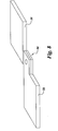
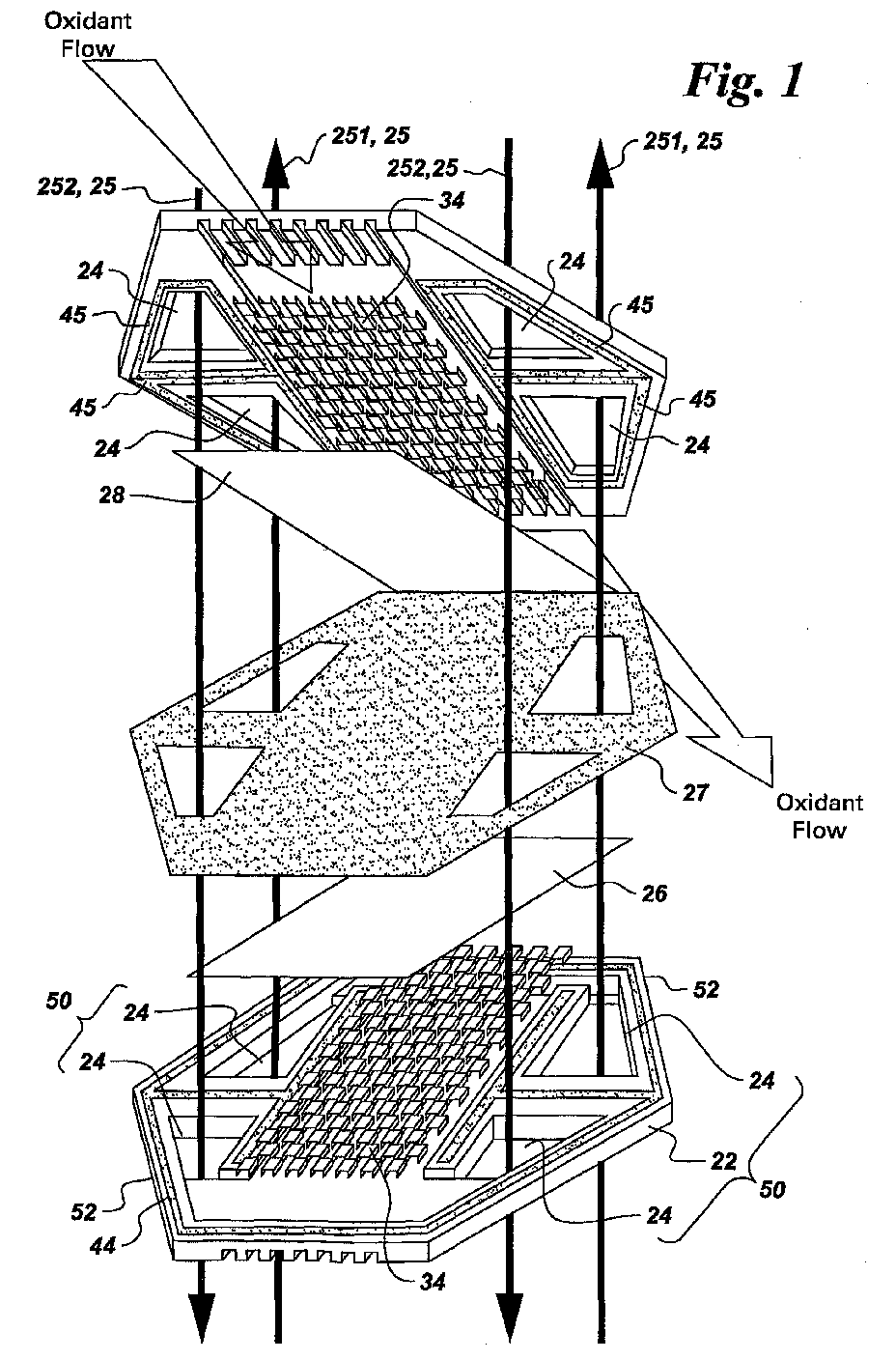
- FIG. 1 illustrates a planar fuel cell unit in exploded view;
- FIG. 2 depicts a fuel cell stack embodiment of the invention in cross-sectional view;
- FIG. 3 shows an exemplary fuel cell module that includes a number of fuel cell stacks arranged in a rectangular configuration;
- FIG. 4 is a top view of a hexagonal embodiment of the fuel cell module;
- FIG. 5 depicts a number of electrical connections between two exemplary fuel cell stacks;
- FIG. 6 is a top view of the fuel cell module of Figure 3;
- FIG. 7 shows another exemplary fuel cell module that includes a number of fuel cell stacks arranged in a rectangular configuration;
- FIG. 8 shows an exemplary electrical connection between two interconnects on neighboring fuel cell stacks; and
- FIG. 9 depicts an exemplary sealing arrangement for the fuel cell unit of Figure 1.
-
- A
fuel cell stack 10 embodiment of the invention is described with reference to Figures 1 and 2. As shown in Figure 2,fuel cell stack 10 includes a number ofinterconnects 22, eachinterconnect 22 defining at least twoopenings 24 in the plane of theinterconnect 22, with eachopening 24 defining a respective fuel manifold 25. As indicated in Figure 1 by arrows, the fuel manifolds 25 include at least one intake fuel manifold 251 and at least one exhaust fuel manifold 252. Although depicted in Figure 1 as being parallel in opposite directions, intake and exhaust manifolds 251, 252 may also be parallel in the same direction or perpendicular. For the particular embodiment depicted in Figure 1, each interconnect defines four, symmetrically arrangedopenings 24, which in turn define four fuel manifolds 25, for symmetric distribution of fuel withinfuel cell stack 10. Eachinterconnect 22 also includes at least oneflow field 34 for flowing a reagent, such as an oxidant or a fuel, acrossinterconnect 22.Exemplary flow fields 34 are formed from metals that possess the requisite electrical conductivity, resist oxidation, maintain mechanical strength and are chemically stable under the operating conditions of the fuel cell. For example, for operating temperatures below 750-800 °C, theflow fields 34 could be stamped from metals compositions based on ferritic, stainless steels. Further, theexemplary flow fields 34 are fit into a channel ininterconnect 22 or form an integral part ofinterconnect 22. -
Fuel cell stack 10 also includes at least onefuel cell unit 20 comprising ananode 26, acathode 28, and anelectrolyte 27 disposed between the anode and the cathode.Exemplary electrolytes 27 are impermeable with respect to both the fuel and the oxidant. For example, for proton exchange membrane (PEM) orSOFC fuel cells 20,exemplary electrolytes 27 aresolid electrolytes 27, such as ion-conducting ceramic or polymer membranes. One exemplary planarfuel cell unit 20 is a solidoxide fuel cell 20, with an oxygen-ion conducting solid electrolyte, such as yttria stabilized zirconia (YSZ), ceria-doped zirconia, or lanthanum strontium gallium manganate (LSGM). - The
anode 26 is positioned adjacent to arespective interconnect 22 and is configured to be in both electrical connection and fluid communication withinterconnect 22. For the embodiment illustrated in Figure 1,flow field 34 supplies both the electrical connection and fluid communication. As indicated in Figure 1, theflow field 34 of thisrespective interconnect 22 is configured to guide a fuel flow from at least one intake fuel manifold 251 to at least one fuel exhaust manifold 252, over the surface ofanode 26. - The
cathode 28 is positioned adjacent to arespective interconnect 22 and is configured to be in both electrical connection and fluid communication withinterconnect 22. As indicated in Figure 1, theflow field 34 of thisrespective interconnect 22 provides the electrical connection tocathode 28 and is configured to guide an oxidant flow across theinterconnect 22 and over the surface ofcathode 28. One exemplary oxidant is air. - In addition,
fuel cell stack 10 includes aperimeter isolation seal 44 disposed around theinterconnect 22 that is adjacent toanode 26. For the particular embodiment shown in Figure 1,perimeter isolation seal 44 also extends inward betweenopenings 24. As indicated in Figure 1, theperimeter isolation seal 44 is disposed on a side of theinterconnect 22 that faces theanode 26 and is configured to seal theelectrolyte 27 to theinterconnect 22. Beneficially,perimeter isolation seal 44 shields anode 26 from the oxidant surrounding planarfuel cell unit 20. To shieldcathode 28 from the fuel flow through fuel manifolds 25,fuel cell stack 10 also includes at least two interior isolation seals 45 disposed on theinterconnect 22 adjacent to thecathode 28 and on a side of theinterconnect 22 facing thecathode 28, as indicated in Figure 1. As shown, oneinterior isolation seal 45 surrounds eachopening 24 and seals theelectrolyte 27 to theinterconnect 22. Beneficially, seals 44, 45 are compressive, as indicated in Figure 1, as compared to the edge seals (not shown) found on typical planar stack designs (not shown). By "compressive," it is meant that seals 44, 45 deform when placed in compression, either from the weight of thestack 10 or a mechanical means, such as tie bolts, to provide a better seal. In order to generate a larger voltage across thestack 10,fuel cell stack 10 includes a number of planarfuel cell units 20 arranged in a vertical stack, according to a particular embodiment. As will be recognized by those skilled in the art, the particular configuration of three (3) planarfuel cell units 20 shown in Figure 2 is for illustrative purposes only, and the specific number of planarfuel cell units 20 included in thestack 10 will vary depending on the power requirements of thestack 10. For the particular embodiment illustrated in Figure 2, each of the two pairs of adjacent planarfuel cell units 20 shares aninterconnect 22, with theinterconnect 22 being adjacent and electrically connected to and in fluid communication with theanode 26 of one of the adjacent planarfuel cell units 20 and with thecathode 28 of the other adjacent planarfuel cell unit 20. For this particular. embodiment, each of theinterconnects 22, which is shared by the adjacent planarfuel cell units 20, includes aflow field 34 on each side of theinterconnect 22, for electrical connection and to provide fluid communication for theadjacent anode 26 andcathode 28 of the neighboring planarfuel cell units 20. - According to a particular embodiment, each planar
fuel cell unit 20 is polygonal, as shown for example in Figure 1. Beneficially, polygonal configurations offuel cell units 20 are relatively easy to manufacture and permit the minimal yet robust sealing arrangements discussed above. For example,corner stack seal 43, shown for example in Figures 3 and 4, need not be completely hermetic but must only provide sufficient resistance to the reactant flow through thestack 10 to maintain the separation of inlet and outlet oxidant flows. For example, corner stack seals 43 may be "leaky seals," that is non-hermetic seals designed with a higher flow resistance that that of fuel cell stacks 10, such that the majority of the fuel and oxidant flows through the fuel cell stacks, rather than throughcorner stack seal 43. Exemplary leaky seals are formed from a compressible cloth or a dense foam. In addition, the polygonal components may be stacked and arranged to form fuel cell stacks 10 prior to insertion in avessel 62. Moreover, the fuel cell stacks 10 are self-aligning when stacked together due to the angles provided by the polygonal shape. For the fuel cell stacks 10 shown in Figure 3, each planarfuel cell unit 20 is rectangular. For thefuel cell stack 10 of Figure 1 and 4, each planarfuel cell unit 20 is hexagonal. More particularly, for the embodiment shown in Figure 1, eachinterconnect 22 defines fouropenings 24, which are arranged in twopairs 50 positioned on two opposing ends 52 of theinterconnect 22, each pair defining an intake fuel manifold 251 and an exhaust fuel manifold 252, as indicated by arrows in Figure 1. Beneficially, this configuration ofopenings 24 facilitates the symmetric distribution of fuel across the planar.fuel cell unit 20. According to a more particular embodiment, the planarfuel cell unit 20 illustrated in Figure 1 is a polygonal solidoxide fuel cell 20. - In order to close the
stack 10 and to collect electrical current from the planarfuel cell units 20, thefuel cell stack 10 embodiment shown in Figure 2, further includes atop end plate 12, which is disposed above an upper one of the planarfuel cell units 20, and abottom end plate 14, which is disposed below a lower one of the planarfuel cell units 20.End plates bottom end plates end plates fuel cell stack 10, preventing the fuel and oxidant from bypassing thefuel cell stack 10. The electric potential between the twoend plates fuel cell stack 10 and equals the sum of the voltages of theindividual cells 20. - According to a particular embodiment, the
electrolyte 27 is impermeable to the reactants (hereinafter "substantially solid") and is deposited ontoanode 26 and the respective one of theinterconnects 22, for example by plasma spray, physical vapor deposition, or chemical vapor deposition techniques. For this particular embodiment, theperimeter isolation seal 44 comprises theelectrolyte 27 and is formed by the deposition of theelectrolyte 27 on therespective interconnect 22. An exemplaryperimeter isolation seal 44 comprisingelectrolyte 27 is shown in Figure 9. For the embodiment of Figure 9, the electrolyte is thicker in an inactive area for sealing, than in the active area. Theelectrolyte 27 can be made thicker, for example by masking during the deposition process prior to assembly offuel cell unit 20. Beneficially, thisperimeter isolation seal 44, formed by direct bonding of theelectrolyte 27 to therespective interconnect 22, is substantially planar and thus does not require maintenance of a certain gap size. The substantiallysolid electrolyte 27 may also be bonded to theanode 26, for example by sintering, with an intermediary layer (not shown) deposited to enhance the bond between theinterconnect 22 and theelectrolyte 27. Otherexemplary seals respective interconnect 22, for example, using one the deposition techniques listed above, to seal theelectrolyte 27 to therespective interconnect 22. Beneficially, these seals. 44, 45 are also substantially planar, thus obviating maintenance of a certain gap size. - A fuel cell module 60 is described with respect to Figures 3, 4, 5, 7 and 8. As shown in Figures 3 and 7, fuel cell module 60 includes a
vessel 62 having aninlet 68 and anoutlet 70, which are configured to respectively receive and exhaust an oxidant, for example air. Fuel cell module 60 further includes at least three fuel cell stacks 10 arranged in a ring withinvessel 62. As shown in Figure 4, the fuel cell stacks 10 separate an inner and anouter volume vessel 62, which are in fluid communication through the fuel cell stacks 10. At least onefuel cell stack 10 has afuel inlet 72, and at least onefuel cell stack 10 has afuel outlet 74, as indicated in top view in Figure 6, for receiving and exhausting a fuel flow, respectively. Eachfuel cell stack 10 includes at least two fuel manifolds 25, for receiving and exhausting the fuel flow, and further includes at least one planar, high-temperaturefuel cell unit 20. As used here, the term "high-temperature" fuel cell refers to a fuel cell having an operating temperature of at least about 600 degrees Celsius, for example a molten carbonate or solid oxide fuel cell. As discussed above, planar, high-temperaturefuel cell unit 20 includes ananode 26, acathode 28, and anelectrolyte 27 disposed between theanode 26 and thecathode 28. - Each
fuel cell stack 10 further includes a number ofseals cathode 28 and the fuel flow through fuel manifolds 25 and for segregating theanode 26 and the oxidant. Beneficially, seals 44, 45 are compressive, as indicated in Figure 1, as compared to the edge seals (not shown) found on typical planar stack designs (not shown). - Fuel cell module 60 further includes a number of
electrical connections 54 between fuel cell stacks 10 for electrically connecting eachfuel cell stack 10 to at least one otherfuel cell stack 10. For the exemplary embodiment shown in Figure 8, theelectrical connections 54 are provided by theinterconnects 22.Jumper wires 54 could also be used to provide theelectrical connections 54 between fuel cell stacks 10, as indicated in Figure 5. Fuel cell stacks 10 may be connected in many ways, with different voltages and redundancies. For example, if thestacks 10 are electrically connected pairwise in parallel, and the two pairs ofstacks 10 are electrically connected in series in the fuel cell module 60 of Figure 3, then fuel cell module 60 provides a voltage equal to the sum of the voltages across a pair ofconnected stacks 10, with a twofold redundancy, due to the parallel current path. Similarly, if all fourstacks 10 are connected in parallel in the fuel cell module 60 of Figure 3, then the voltage supplied by fuel cell module 60 is limited to the voltage of asingle stack 10, but the redundancy is four-fold. - According to a particular embodiment,
vessel 62 is apressure vessel 62. Using apressure vessel 62 is beneficial, in thatpressure vessel 62 is configured to force the oxidant through fuel cell stacks 10, such that the oxidant contacts theporous cathodes 28. Specific pressures vary with power generation applications. However, oneexemplary pressure vessel 62 is configured to operate in a range of about three (3) to about ten (10) atmospheres. Beneficially, use of apressure vessel 62 provides higher pressure reactants, to achievehigher fuel cell 20 voltages. For the particular embodiment illustrated in Figure 3,inlet 68 is configured to receive the oxidant into theinner volume 64 ofvessel 62, andoutlet 70 is configured to exhaust the oxidant from theouter volume 66 ofvessel 62. For this embodiment, each planar, high-temperaturefuel cell unit 20 is configured to convey the oxidant from theinner volume 64 to theouter volume 66 of thevessel 62. One benefit of the configuration shown in Figure 3 is that fuel in the pipes between thestacks 10 is heated by the hot exhaust oxidant flow. For the embodiment illustrated in Figure 7, theinlet 68 is configured to receive the oxidant into theouter volume 66 ofvessel 62, and theoutlet 70 is configured to exhaust the oxidant from theinner volume 64 ofvessel 62. For the embodiment of Figure 7, each planar, high-temperaturefuel cell unit 20 is configured to convey the oxidant from theouter volume 66 to theinner volume 64 of thevessel 62. This latter embodiment cools thestacks 10 with incoming oxidant flow. Beneficially, both of these configurations facilitate enclosingstacks 10 withinvessels 62 similar to those currently designed for gas turbine applications. - Exemplary planar high-temperature
fuel cell units 20 are described above with respect to Figure 1 and includeinterconnects 22 definingopenings 24, which in turn define fuel manifolds 25, and including flow fields 34. As is also discussed above with reference to Figure 1, for the exemplary planar high-temperaturefuel cell units 20, thecompressive seals electrical connections 54 are formed betweeninterconnects 22, for example as shown in Figure 8, with at least twointerconnects 22 in respective fuel cell stacks 10 being electrically connected. Alternatively, interconnects 22 in respective fuel cell stacks are connected withexternal connectors 54, such asjumper wires 54. - In order to generate larger voltages, in a more particular embodiment, each
fuel cell stack 10 includes a number of planar, high-temperaturefuel cell units 20 arranged in a vertical stack. As indicated in Figure 5, each planar high-temperaturefuel cell unit 20 is disposed in a respective plane 90. For this embodiment, eachelectrical connection 54 is configured to connectinterconnects 22 adjacent to at least two planar, high-temperaturefuel cell units 20 in a respective plane 90, as indicated in Figure 5. Theelectrical connections 54 may be provided byinterconnects 22, as shown in Figure 8. According to a more particular embodiment illustrated by Figure 2, at least one pair of adjacent planar, high-temperaturefuel cell units 20 within each of the fuel cell stacks 10 shares arespective interconnect 22, with theinterconnect 22 being adjacent to and in both electrical connection and fluid communication with theanode 26 of one of the adjacent planar, high-temperaturefuel cell units 20 and with thecathode 28 of the other adjacent planar, high-temperaturefuel cell unit 20. For this particular embodiment, each of theinterconnects 22, which is shared by adjacent planar, high-temperaturefuel cell units 20, includes aflow field 34 on each side of theinterconnect 22, to electrically connect and to supply fluid communication for theadjacent anode 26 andcathode 28 of the neighboring planar, high-temperaturefuel cell units 20. Further, as discussed above with reference to Figure 2, exemplary fuel cell stacks 10 include atop end plate 12 disposed above an upper one of the planar, high-temperaturefuel cell units 20 and abottom end plate 14 disposed below a lower one of the planar, high-temperaturefuel cell units 20, for closing thestacks 10. - As noted above, the
stacks 10 may be connected in a number of ways, depending on the desired power outputs and redundancies for fuel cell module 60. To provide a number of redundant current paths, in one embodiment theelectrical connections 54 connect all of the planar high-temperaturefuel cell units 20 within at least one of the planes 90. For example, for the fourstack 10 configuration of Figures 3 and 7, fourelectrical connections 54 connect the four planar, high-temperature fuel cell units in one plane 90, providing a fourfold current path redundancy but supplying a voltage limited to the voltage across a single one of the four stacks 10. To increase the voltage output of fuel cell module 60 while providing a twofold current path redundancy, for another embodiment, anelectrical connection 54 connects apair 80 of fuel cell stacks 10, and anotherelectrical connection 54 connects asecond pair 82 of fuel cell stacks 10, for the fourstack 10 configuration of Figures 3 and 7. To maintain a constant output, when onefuel cell unit 20 fails to conduct, the current in the remaining stacks at the failed cell unit's level of the parallel path must increase accordingly. For example, for two cell units so linked, the current in the surviving cell doubles. For a six stack configuration, each of the surviving cells within the parallel path must carry an additional twenty percent (20%) more current. The minimum number of stacks so connected will thus depend on the amount of additional current that individualfuel cell units 20 can tolerate, which in turn depends in part on the type of fuel cells used. - To transfer the exhaust of partially reacted fuel from one
stack 10 to anotherstack 10, the fuel cell module 60 according to another embodiment, further includes at least oneheat exchanger 56, which connects apair 80 of fuel cell stacks 10. For Figure 3,exemplary pairs 80 include the pair offuel stacks 10 that are labeled 1 and 2 and the pair offuel stacks 10 that are labeled 3 and 4.Exemplary heat exchangers 56 include apipe 56 and apipe 56 equipped with heat exchange enhancement features, such as fins (not shown), andheat exchanger 56 is configured to supply the fuel flow exhausted from one of pair of fuel cell stacks to a second of pair of fuel cell stacks. For the arrangement shown in Figure 7,heat exchangers 56 are surrounded by oxidant frominlet 68, thereby beneficially cooling the exhaust fuel inpipes 56 and heating the oxidant entering the fuel cell stacks 10. In order to adjust the inlet temperature and fuel composition of the fuel entering the downstream stack 10 (for example,stack 2 in thestack down stream stack 10, for example as shown in Figure 7. For another embodiment, the fuel cell stacks 10 are designed such that fuel utilization in the upstream stack 10 (for example,stack 1 in thestack fuel cell unit 20 that is actually reacted by thefuel cell unit 20, is controlled using several design parameters, such as the distribution and concentration of reactants in thefuel cell unit 20. - For the particular embodiments of fuel cell module 60 shown in Figures 3, 6, and 7, fuel cell module 60 includes four fuel cell stacks 10 arranged in a ring and at least two
heat exchangers 56, which connect thepair 80 of fuel cell stacks 10 and connect asecond pair 82 of fuel cell stacks 10, respectively. For these embodiments, the planar, high-temperaturefuel cell units 20 are rectangular, and each pair of fuel cell stacks includes arespective fuel inlet 72 for receiving the fuel flow and arespective fuel outlet 74 for exhausting the fuel flow. Exemplary planar, high-temperaturefuel cell units 20 areplanar SOFC units 20. In addition, fuel cell module 60 further includes afuel feed line 76, which is configured to supply thefuel inlets 72, and afuel exhaust line 78, which is configured to exhaust thefuel outlets 74. Fuel is supplied tofuel inlets 72, either prereformed or as a hydrocarbon, which is reformed within the stack, to form hydrogen (H2) and carbon monoxide (CO). For example, the fuel is reformed within intake fuel manifold 251 or within theanode 26. In another example, the planar, high-temperaturefuel cell units 20 incorporate an internal reformer (not shown) ahead ofanode 26. Beneficially, reforming the hydrocarbon fuel withinfuel cell units 20 enhances system efficiency. - Another embodiment of fuel cell module 60 is illustrated in Figure 4 in top view. For this embodiment, fuel cell module 60 includes six fuel cell stacks 10 arranged in a ring and at least four
heat exchangers 56 connecting thepair 80 of fuel cell stacks 10, and connecting a second, a third, and afourth pair fuel cell units 20 are hexagonal. Exemplary planar, high-temperaturefuel cell units 20 compriseplanar SOFC units 20. Further, both thepair 80 and thesecond pair 82 of fuel cell stacks 10 include arespective fuel inlet 72 for receiving the fuel flow, and each of the third andfourth pairs respective fuel outlet 74 for exhausting the fuel flow. In addition, fuel cell module 60 further includes afuel feed line 76, which is configured to supply thefuel inlets 72, and afuel exhaust line 78, which is configured to exhaust thefuel outlets 74. Fuel is supplied tofuel inlets 72, either prereformed or as a hydrocarbon, which is reformed within the stack, for example the planar high-temperaturefuel cell units 20 may incorporate an internal reformer (not shown) ahead ofanode 26, to form hydrogen (H2) and carbon monoxide (CO) from a hydrocarbon fuel. Thestacks 10 may be connected in a number of ways, depending on the desired power outputs and redundancies for fuel cell module 60. For one embodiment, theelectrical connections 54 connect two of the fuel cell stacks 10 together in parallel, connect another two of the fuel cell stacks 10 together in parallel, and connect the remaining two of the fuel cell stacks 10 together in parallel. For another embodiment, theelectrical connections 54 connect three of the fuel cell stacks 10 together in parallel, and connect another three of the fuel cell stacks 10 together in parallel. In another embodiment, theelectrical connections 54 connect each of the fuel cell stacks 10 together, to provide a six-fold current path redundancy. As discussed above, exemplaryelectrical connections 54 are formed between theinterconnects 22 of the respective stacks 10. - Although only certain features of the invention have been illustrated and described herein, many modifications and changes will occur to those skilled in the art. For example, it should be clear that the location of the fuel and air flow paths can be reversed, with the appropriate changes in the locations of the cathode and anode. Similarly, the fuel cell stack and fuel cell module could be assembled to have the oxidant internally manifolded and the fuel surrounding the stack.
- For the sake of good order, various aspects of the invention are set out in the following clauses:-
- 1. A fuel cell stack (10) comprising:
- a plurality of interconnects (22), each of said interconnects defining at least two openings (24) and comprising at least one flow field (34) for flowing a reagent, each of said at least two openings defining a respective fuel manifold (25), said fuel manifolds comprising at least one intake fuel manifold (251 ) and at least one exhaust fuel manifold (252);
- at least one fuel cell unit (20) comprising an anode (26), a cathode (28), and an electrolyte (27) disposed between said anode and said cathode, wherein said anode is positioned adjacent to a respective one of said interconnects and is configured to be in both electrical connection and fluid communication with said interconnect, said flow field of said interconnect being configured to guide a fuel flow from said at least one intake fuel manifold to said at least one fuel exhaust manifold, and wherein said cathode is positioned adjacent to another respective one of said interconnects and configured to be in both electrical connection and fluid communication with said another interconnect, said flow field of said another interconnect being configured to guide an oxidant flow across said another interconnect;
- a perimeter isolation seal (44) disposed around the respective one of said interconnects adjacent to said anode, said perimeter isolation seal being disposed on a side of said interconnect facing said anode and being configured to seal said electrolyte to said interconnect; and
- at least two interior isolation seals (45) disposed on the respective one of said interconnects adjacent to said cathode and on a side of said interconnect facing said cathode, one interior isolation seal surrounding each of said openings and being configured to seal said electrolyte to said interconnect.
- 2. The fuel cell stack (10) of
Clause 1, wherein said at least one planar fuel cell unit (20) comprises a solid oxide fuel cell (20). - 3. The fuel cell stack (10) of
Clause 1, comprising a plurality of planar fuel cell units (20) arranged in a vertical stack. - 4. The fuel cell stack (10) of
Clause 3, wherein at least one pair of adjacent planar fuel cell units (20) share one of said interconnects (22), said interconnect being adjacent to and in both electrical connection and fluid communication with said anode (26) of one of said planar fuel cell units and said cathode (28) of the other of said planar fuel cell units. - 5. The fuel cell stack (10) of
Clause 3, wherein each of said at least one planar fuel cell units (20) is polygonal. - 6. The fuel cell stack (10) of
Clause 5, wherein each of said at least one planar fuel cell units (20) is rectangular. - 7. The fuel cell stack (10) of
Clause 5, wherein each of said at least one planar fuel cell units (20) is hexagonal. - 8. The fuel cell stack (10) of Clause 7, wherein each of said interconnects (22) defines four openings (24) which are arranged in two pairs (50) positioned on two opposing ends (52) of said interconnect, each pair defining an intake fuel manifold (251 ) and an exhaust fuel manifold (252).
- 9. The fuel cell stack (10) of
Clause 5, wherein each of said planar fuel cell units (20) comprises a polygonal solid oxide fuel cell (20). - 10. The fuel cell stack (10) of Clause 9, further comprising:
- a top end plate (12) disposed above an upper one of said planar fuel cell units (20); and
- a bottom end plate (14) disposed below a lower one of said planar fuel cell units.
- 11. The fuel cell stack (10) of Clause 9, wherein said electrolyte (27) is substantially solid and is deposited onto said anode (26) and the respective one of said interconnects (22), said perimeter isolation seal (44) comprising said electrolyte and being formed by depositing said electrolyte on said interconnect.
- 12. A fuel cell module (60) comprising:
- a vessel (62) having an inlet (68) and an outlet (70), said inlet and outlet being configured to receive and exhaust an oxidant, respectively;
- at least three fuel cell stacks (10) arranged in a ring within said vessel, said fuel cell stacks separating an inner and an outer volume (64, 66) of said vessel, said inner and outer volumes being in fluid communication through said fuel cell stacks, at least one of said fuel cell stacks having a fuel inlet (72) and at least one of said fuel cell stacks having a fuel outlet (74) for receiving and exhausting a fuel flow, respectively, wherein each fuel cell stack comprises at least two fuel manifolds (25) for receiving and exhausting the fuel flow and further comprises at least one planar high-temperature fuel cell unit (20) comprising an anode (26), a cathode (28), and an electrolyte (27) disposed between said anode and cathode, each fuel cell stack further comprising a plurality of compressive seals (44, 45) for segregating said cathode and the fuel flow through said fuel manifolds and for segregating said anode and the oxidant; and
- 13. The fuel cell module (60) of
Clause 12, wherein said vessel (62) comprises a pressure vessel (62), and wherein said planar high-temperature fuel cell units (20) comprise planar solid oxide fuel cell (SOFC) units (20). - 14. The fuel cell module (60) of
Clause 12, wherein said inlet (68) is configured to receive the oxidant into said outer volume (66) of said vessel (62) and said outlet (70) is configured to exhaust the oxidant from said inner volume (64) of said vessel, and wherein each of said planar high-temperature fuel cell units (20) is configured to convey the oxidant from said outer volume to said inner volume of said vessel. - 15. The fuel cell module (60) of
Clause 12, wherein said inlet (68) is configured to receive the oxidant into said inner volume (64) of said vessel (62) and said outlet (70) is configured to exhaust the oxidant from said outer volume (66) of said vessel, and wherein each of said planar high-temperature fuel cell units (20) is configured to convey the oxidant from said inner volume to said outer volume of said vessel. - 16. The fuel cell module (60) of
Clause 12, wherein each of said fuel cell stacks (10) further comprises a plurality of interconnects (22), each of said interconnects defining at least two openings (24), each opening defining a respective one of said fuel manifolds (25), said fuel manifolds comprising at least one fuel intake manifold (251) and at least one fuel exhaust manifold (252), and each interconnect further comprising at least one flow field (34) for flowing a reagent,
wherein each anode (26) is positioned adjacent to a respective one of said interconnects (22) and is configured to be in both electrical connection and fluid communication with said interconnect, and wherein said flow field of said interconnect is configured to guide the fuel flow from said at least one fuel intake manifold to said at least one fuel exhaust manifold,
wherein each cathode (28) is positioned adjacent to a respective one of said interconnects and is configured to be in both electrical connection and fluid communication with said interconnect, said flow field of said interconnect being configured to guide an oxidant flow across said interconnect, and
wherein at least two of said interconnects in respective fuel cell stacks are electrically connected, providing said electrical connections (54) between said fuel cell stacks. - 17. The fuel cell module (60) of Clause 16, wherein said seals (44, 45)
comprise:
- a perimeter isolation seal (44) disposed around the respective one of said interconnects (22) adjacent to said anode (26), said perimeter isolation seal being disposed on a side of said interconnect facing said anode and being configured to seal said electrolyte (27) to said interconnect; and
- at least two interior isolation seals (45) disposed on the respective one of said interconnects adjacent to said cathode (28) and on a side of said interconnect facing said cathode, one interior isolation seal surrounding each of said openings (24) and being configured to seal said electrolyte to said interconnect.
- 18. The fuel cell module (60) of Clause 17, further comprising a plurality of corner stack seals (43), each of said corner stack seals being disposed along an edge joining two of said fuel cell stacks (10), wherein each of the corner stack seals comprises a leaky seal.
- 19. The fuel cell module (60) of Clause 17, further comprising a plurality of corner stack seals (43), each of said corner stack seals being disposed along a face joining two of said fuel cell stacks (10), wherein each of the corner stack seals comprises a leaky seal.
- 20. The fuel cell module (60) of Clause 17, wherein each of said fuel cell
stacks (10) comprises a plurality of planar high-temperature fuel cell units (20)
arranged in a vertical stack, wherein each of said planar high-temperature
fuel cell units is disposed in one of a respective plurality of planes (90), and
wherein said interconnects (22) of at least two of said planar high-temperature fuel cell units in a respective plane are electrically connected. - 21. The fuel cell module (60) of
Clause 20, wherein at least one pair of adjacent planar high-temperature fuel cell units (20) within each of said fuel cell stacks (10) share a respective one of said interconnects (22), said interconnect being adjacent to and in both electrical connection and fluid communication with said anode (26) of one of said planar high-temperature fuel cell units and said cathode (28) of the other of said planar high-temperature fuel cell units. - 22. The fuel cell module (60) of
Clause 20, wherein each of said fuel cell stacks (10) further comprises: - a top end plate (12) disposed above an upper one of said planar high-temperature fuel cell units (20); and
- a bottom end plate (14) disposed below a lower one of said planar high-temperature fuel cell units.
- 23. The fuel cell module (60) of
Clause 20, wherein all of said planar high-temperature fuel cell units (20) within at least one of said planes (90) are electrically connected. - 24. The fuel cell module (60) of
Clause 20, further comprising at least one heat exchanger (56) connecting a pair (80) of said fuel cell stacks (10) and configured to supply the fuel flow exhausted from one of said pair of fuel cell stacks to a second of said pair of fuel cell stacks. - 25. The fuel cell module (60) of
Clause 24 comprising four fuel cell stacks (10) arranged in a ring and at least two heat exchangers (56) connecting said pair (80) of fuel cell stacks and connecting a second pair (82) of said fuel cell stacks, respectively,
wherein each of said planar high-temperature fuel cell units (20) is rectangular, and wherein each of said pairs of fuel cell stacks includes a respective fuel inlet (72) for receiving the fuel flow and a respective fuel outlet (74) for exhausting the fuel flow,
said fuel cell module further comprising: - a fuel feed line (76) configured to supply said fuel inlets; and
- a fuel exhaust line (78) configured to exhaust said fuel outlets.
- 26. The fuel cell module (60) of Clause 25, wherein each of said pair and said second pair of said fuel cell stacks (10) is electrically connected.
- 27. The fuel cell module (60) of Clause 25, wherein all of said fuel cell stacks (10) are electrically connected.
- 28. The fuel cell module (60) of
Clause 24, comprising six fuel cell stacks (10) arranged in a ring and at least four heat exchangers (56) connecting said pair (80) of fuel cell stacks, and connecting a second, a third, and a fourth pair (82, 84, 86) of said fuel cell stacks, respectively,
wherein each of said planar high-temperature fuel cell units (20) is hexagonal, wherein each of said pair and said second pair of fuel cell stacks includes a respective fuel inlet (72) for receiving the fuel flow, and wherein each of said third and fourth pairs of fuel cell stacks includes a respective fuel outlet (74) for exhausting the fuel flow,
said fuel cell module further comprising: - a fuel feed line (76) configured to supply said fuel inlets; and
- a fuel exhaust line (78) configured to exhaust said fuel outlets.
- 29. The fuel cell module (60) of
Clause 28, wherein two of said fuel cell stacks (10) are electrically connected, wherein another two of said fuel cell stacks are electrically connected, and wherein a remaining two of said fuel cell stacks are electrically connected. - 30. The fuel cell module (60) of
Clause 28, wherein three of said fuel cell stacks (10) are electrically connected, and wherein another three of said fuel cell stacks are electrically connected. - 31. The fuel cell module (60) of
Clause 28, wherein all of said fuel cell stacks (10) are electrically connected together. -
a plurality of electrical connections (54) between said fuel cell stacks for electrically connecting each fuel cell stack to at least one other of said fuel cell stacks.
Claims (10)
- A fuel cell stack (10) comprising:a plurality of interconnects (22), each of said interconnects defining at least two openings (24) and comprising at least one flow field (34) for flowing a reagent, each of said at least two openings defining a respective fuel manifold (25), said fuel manifolds comprising at least one intake fuel manifold (251) and at least one exhaust fuel manifold (252);at least one fuel cell unit (20) comprising an anode (26), a cathode (28), and an electrolyte (27) disposed between said anode and said cathode, wherein said anode is positioned adjacent to a respective one of said interconnects and is configured to be in both electrical connection and fluid communication with said interconnect, said flow field of said interconnect being configured to guide a fuel flow from said at least one intake fuel manifold to said at least one fuel exhaust manifold, and wherein said cathode is positioned adjacent to another respective one of said interconnects and configured to be in both electrical connection and fluid communication with said another interconnect, said flow field of said another interconnect being configured to guide an oxidant flow across said another interconnect;a perimeter isolation seal (44) disposed around the respective one of said interconnects adjacent to said anode, said perimeter isolation seal being disposed on a side of said interconnect facing said anode and being configured to seal said electrolyte to said. interconnect; andat least two interior isolation seals (45) disposed on the respective one of said interconnects adjacent to said cathode and on a side of said interconnect facing said cathode, one interior isolation seal surrounding each of said openings and being configured to seal said electrolyte to said interconnect.
- The fuel cell stack (10) of Claim 1, comprising a plurality of planar fuel cell units (20) arranged in a vertical stack.
- The fuel cell stack (10) of Claim 2, wherein at least one pair of adjacent planar fuel cell units (20) share one of said interconnects (22), said interconnect being adjacent to and in both electrical connection and fluid communication with said anode (26) of one of said planar fuel cell units and said cathode (28) of the other of said planar fuel cell units.
- A fuel cell module (60) comprising:wherein each fuel cell stack comprises at least two fuel manifolds (25) for receiving and exhausting the fuel flow and further comprises at least one planar high-temperature fuel cell unit (20) comprising an anode (26), a cathode (28), and an electrolyte (27) disposed between said anode and cathode, each fuel cell stack further comprising a plurality of compressive seats (44, 45) for segregating said cathode and the fuel flow through said fuel manifolds and for segregating said anode and the oxidant; anda vessel (62) having an inlet (68) and an outlet (70), said inlet and outlet being configured to receive and exhaust an oxidant, respectively;at least three fuel cell stacks (10) arranged in a ring within said vessel, said fuel cell stacks separating an inner and an outer volume (64, 66) of said vessel, said inner and outer volumes being in fluid communication through said fuel cell stacks, at least one of said fuel cell stacks having a fuel inlet (72) and at least one of said fuel cell stacks having a fuel outlet (74) for receiving and exhausting a fuel flow, respectively,
a plurality of electrical connections (54) between said fuel cell stacks for electrically connecting each fuel cell stack to at least one other of said fuel cell stacks. - The fuel cell module (60) of Claim 4, wherein said vessel (62) comprises a pressure vessel (62), and wherein said planar high-temperature fuel cell units (20) comprise planar solid oxide fuel cell (SOFC) units (20).
- The fuel cell module (60) of Claim 4, wherein said inlet (68) is configured to receive the oxidant into said outer volume (66) of said vessel (62) and said outlet (70) is configured to exhaust the oxidant from said inner volume (64) of said vessel, and wherein each of said planar high-temperature fuel cell units (20) is configured to convey the oxidant from said outer volume to said inner volume of said vessel.
- The fuel cell module (60) of Claim 4, wherein said inlet (68) is configured to receive the oxidant into said inner volume (64) of said vessel (62) and said outlet (70) is configured to exhaust the oxidant from said outer volume (66) of said vessel, and wherein each of said planar high-temperature fuel cell units (20) is configured to convey the oxidant from said inner volume. to said outer volume of said vessel.
- The fuel cell module (60) of Claim 4, wherein each of said fuel cell stacks (10) further comprises a plurality of interconnects (22), each of said interconnects defining at least two openings (24), each opening defining a respective one of said fuel manifolds (25), said fuel manifolds comprising at least one fuel intake manifold (251) and at least one fuel exhaust manifold (252), and each interconnect further comprising at least one flow field (34) for flowing a reagent,
wherein each anode (26) is positioned adjacent to a respective one of said interconnects (22) and is configured to be in both electrical connection and fluid communication with said interconnect, and wherein said flow field of said interconnect is configured to guide the fuel flow from said at least one fuel intake manifold to said at least one fuel exhaust manifold,
wherein each cathode (28) is positioned adjacent to a respective one of said interconnects and is configured to be in both electrical connection and fluid communication with said interconnect, said flow field of said interconnect being configured to guide an oxidant flow across said interconnect, and
wherein at least two of said interconnects in respective fuel cell stacks are electrically connected, providing said electrical connections (54) between said fuel cell stacks. - The fuel cell module (60) of Claim 8, wherein said seals (44, 45) comprise:a perimeter isolation seal (44) disposed around the respective one of said interconnects (22) adjacent to said anode (26), said perimeter isolation seal being disposed on a side of said interconnect facing said anode and being configured to seal said electrolyte (27) to said interconnect; andat least two interior isolation seals (45) disposed on the respective one of said interconnects adjacent to said cathode (28) and on a side of said interconnect facing said cathode, one interior isolation seal surrounding each of said openings (24) and being configured to seal said electrolyte to said interconnect.
- The fuel cell module (60) of Claim 9, wherein each of said fuel cell stacks (10) comprises a plurality of planar high-temperature fuel cell units (20) arranged in a vertical stack, wherein each of said planar high-temperature fuel cell units is disposed in one of a respective plurality of planes (90), and wherein said interconnects (22) of at least two of said planar high-temperature fuel cell units in a respective plane are electrically connected.
Applications Claiming Priority (2)
| Application Number | Priority Date | Filing Date | Title |
|---|---|---|---|
| US10/064,886 US6844100B2 (en) | 2002-08-27 | 2002-08-27 | Fuel cell stack and fuel cell module |
| US64886 | 2002-08-27 |
Publications (2)
| Publication Number | Publication Date |
|---|---|
| EP1443583A2 true EP1443583A2 (en) | 2004-08-04 |
| EP1443583A3 EP1443583A3 (en) | 2004-08-11 |
Family
ID=31975626
Family Applications (1)
| Application Number | Title | Priority Date | Filing Date |
|---|---|---|---|
| EP03255039A Withdrawn EP1443583A3 (en) | 2002-08-27 | 2003-08-13 | Fuel cell stack and fuel cell module |
Country Status (8)
| Country | Link |
|---|---|
| US (2) | US6844100B2 (en) |
| EP (1) | EP1443583A3 (en) |
| JP (1) | JP4651923B2 (en) |
| KR (1) | KR20040018971A (en) |
| CN (1) | CN1495955A (en) |
| AU (1) | AU2003235149A1 (en) |
| CA (1) | CA2437916A1 (en) |
| SG (1) | SG131763A1 (en) |
Cited By (1)
| Publication number | Priority date | Publication date | Assignee | Title |
|---|---|---|---|---|
| DE102022106825A1 (en) | 2022-03-23 | 2023-09-28 | Audi Aktiengesellschaft | Module box, method for producing a module box, fuel cell device and fuel cell vehicle |
Families Citing this family (38)
| Publication number | Priority date | Publication date | Assignee | Title |
|---|---|---|---|---|
| NL1019397C2 (en) * | 2001-11-19 | 2003-06-13 | Willem Jan Oosterkamp | Fuel cell stack in a pressure vessel. |
| JP3699063B2 (en) * | 2002-06-26 | 2005-09-28 | 本田技研工業株式会社 | Fuel cell and control method thereof |
| CA2497808A1 (en) * | 2002-09-06 | 2004-03-18 | William R. Richards | Modular fuel cell |
| AU2003285243A1 (en) * | 2002-11-28 | 2004-06-18 | Global Thermoelectric Inc. | Solid oxide fuel cell stack |
| CN100492740C (en) * | 2004-03-30 | 2009-05-27 | 加利福尼亚技术学院 | Direct alcohol fuel cells using solid acid electrolytes |
| US7323270B2 (en) * | 2004-08-11 | 2008-01-29 | Fuelcell Energy, Inc. | Modular fuel-cell stack assembly |
| US8048576B2 (en) | 2005-07-12 | 2011-11-01 | Honeywell International Inc. | Power generator shut-off valve |
| US7914943B2 (en) * | 2005-08-19 | 2011-03-29 | Daimler Ag | Integrated seal for fuel cell assembly and fuel cell stack |
| US7713642B2 (en) * | 2005-09-30 | 2010-05-11 | General Electric Company | System and method for fuel cell operation with in-situ reformer regeneration |
| US7727655B2 (en) * | 2005-10-25 | 2010-06-01 | Honeywell International Inc. | Fuel cell stack having catalyst coated proton exchange member |
| US7811690B2 (en) * | 2005-10-25 | 2010-10-12 | Honeywell International Inc. | Proton exchange membrane fuel cell |
| US8043736B2 (en) * | 2006-01-10 | 2011-10-25 | Honeywell International Inc. | Power generator having multiple layers of fuel cells |
| US20070178340A1 (en) * | 2006-01-31 | 2007-08-02 | Honeywell International Inc. | Fuel cell power generator with micro turbine |
| US20070184315A1 (en) * | 2006-02-09 | 2007-08-09 | Kelly Sean M | Control of fuel cell stack electrical operating conditions |
| US7966830B2 (en) * | 2006-06-29 | 2011-06-28 | The Boeing Company | Fuel cell/combustor systems and methods for aircraft and other applications |
| US8283079B2 (en) * | 2006-11-03 | 2012-10-09 | Honeywell International Inc. | Fuel cell power generator with water reservoir |
| US8822097B2 (en) | 2006-11-30 | 2014-09-02 | Honeywell International Inc. | Slide valve for fuel cell power generator |
| TWI326134B (en) * | 2006-12-21 | 2010-06-11 | Ind Tech Res Inst | Fuel cell module |
| EP2132814B1 (en) * | 2007-04-02 | 2012-02-22 | Staxera GmbH | Contact arrangement and method for assembling a fuel cell stack from at least one contact arrangement |
| WO2008131078A1 (en) * | 2007-04-17 | 2008-10-30 | Modine Manufacaturing Company | Solid oxide fuel cell unit for use in distributed power generation |
| WO2008131051A1 (en) | 2007-04-17 | 2008-10-30 | Modine Manufacturing Company | Fuel cell system with partial external reforming and direct internal reforming |
| GB0715218D0 (en) * | 2007-08-03 | 2007-09-12 | Rolls Royce Fuel Cell Systems | A fuel cell and a method of manufacturing a fuel cell |
| EP2291878A2 (en) * | 2008-05-30 | 2011-03-09 | Corning Incorporated | Solid oxide fuel cell systems |
| WO2010053474A1 (en) * | 2008-11-05 | 2010-05-14 | Utc Power Corporation | Fuel cell support structure and method of assembly/disassembly thereof |
| US8268504B2 (en) * | 2008-12-22 | 2012-09-18 | General Electric Company | Thermomechanical sealing of interconnect manifolds in fuel cell stacks |
| CN102460818B (en) | 2009-06-12 | 2014-08-27 | 益达科技有限责任公司 | Systems and methods for independently controlling the operation of fuel cell stacks and fuel cell systems incorporating the same |
| US8304136B2 (en) * | 2009-09-10 | 2012-11-06 | Samsung Electro-Mechanics Co., Ltd. | Solid oxide fuel cell and solid oxide fuel cell bundle |
| EP2333883A1 (en) * | 2009-11-18 | 2011-06-15 | Forschungszentrum Jülich Gmbh (FJZ) | Anode for a high temperature fuel cell and production of same |
| US8530106B2 (en) * | 2010-05-21 | 2013-09-10 | GM Global Technology Operations LLC | End cell thermal barrier having variable properties |
| KR20120007772A (en) * | 2010-07-15 | 2012-01-25 | 삼성에스디아이 주식회사 | Solid oxide fuel cell and stack thereof |
| JP6016520B2 (en) * | 2012-08-22 | 2016-10-26 | 三菱日立パワーシステムズ株式会社 | Fuel cell module |
| JP6165609B2 (en) * | 2013-12-05 | 2017-07-19 | 三菱日立パワーシステムズ株式会社 | Fuel cell and operation method thereof |
| CA3062176C (en) | 2017-05-04 | 2024-01-23 | Versa Power Systems Ltd. | Compact high temperature electrochemical cell stack architecture |
| CN109509895A (en) * | 2018-12-20 | 2019-03-22 | 中国地质大学(武汉) | A kind of solid oxide fuel cell |
| DE102019110317A1 (en) * | 2019-04-18 | 2020-10-22 | e.Go REX GmbH | Modular range extender system for an electrically powered motor vehicle and an electrically powered motor vehicle with a range extender |
| CA3147747A1 (en) * | 2019-07-16 | 2021-01-21 | Ch Innovations Inc. | Compact fuel cell modules and assemblies |
| EP4102603A2 (en) * | 2019-07-16 | 2022-12-14 | FCP Fuel Cell Powertrain GmbH | Fuel cell system and integration backplane for fuel cell modules |
| CN112701334B (en) * | 2020-12-25 | 2023-03-21 | 上海韵量新能源科技有限公司 | Diagnosis method for cathode-anode reversal of membrane electrode in electric pile |
Citations (9)
| Publication number | Priority date | Publication date | Assignee | Title |
|---|---|---|---|---|
| US4910100A (en) * | 1989-07-21 | 1990-03-20 | Fuji Electric Co., Ltd. | Solid electrolyte fuel cell |
| JPH0547408A (en) * | 1991-08-09 | 1993-02-26 | Fuji Electric Co Ltd | Solid electrolyte-type fuel cell |
| DE4343914A1 (en) * | 1993-12-22 | 1994-06-30 | Wolfgang Prof Dr Winkler | Enclosure construction for high temperature fuel cells |
| US5811202A (en) * | 1997-08-05 | 1998-09-22 | M-C Power Corporation | Hybrid molten carbonate fuel cell with unique sealing |
| US6045935A (en) * | 1998-02-27 | 2000-04-04 | Corning Incorporated | Flexible inorganic electrolyte fuel cell design |
| US6132895A (en) * | 1998-03-09 | 2000-10-17 | Motorola, Inc. | Fuel cell |
| WO2002023660A2 (en) * | 2000-09-12 | 2002-03-21 | Nissan Motor Co.,Ltd. | Fuel cell with solid polymer membrane to be moisturized, fuel cell system, and moisturizing method for fuel cell |
| US6361892B1 (en) * | 1999-12-06 | 2002-03-26 | Technology Management, Inc. | Electrochemical apparatus with reactant micro-channels |
| US6406807B1 (en) * | 1999-09-17 | 2002-06-18 | Plug Power Inc. | Distribution of hydration fluid in a fuel cell |
Family Cites Families (11)
| Publication number | Priority date | Publication date | Assignee | Title |
|---|---|---|---|---|
| DE4324907A1 (en) | 1993-07-24 | 1995-01-26 | Dornier Gmbh | Interconnection of fuel cells |
| US20030012997A1 (en) * | 1994-08-08 | 2003-01-16 | Hsu Michael S. | Pressurized, integrated electrochemical converter energy system |
| US5549983A (en) | 1996-01-22 | 1996-08-27 | Alliedsignal Inc. | Coflow planar fuel cell stack construction for solid electrolytes |
| JPH11233128A (en) * | 1998-02-17 | 1999-08-27 | Honda Motor Co Ltd | Fuel cell |
| US6444339B1 (en) * | 2000-07-24 | 2002-09-03 | Microcell Corporation | Microcell electrochemical device assemblies with thermal management subsystem, and method of making and using the same |
| DE60141634D1 (en) | 2000-08-18 | 2010-05-06 | Versa Power Systems Ltd | HIGH-TEMPERATURE-RESISTANT GAS SEALS |
| EP1344267A2 (en) * | 2000-11-08 | 2003-09-17 | Global Thermoelectric Inc. | Fuel cell interconnect |
| JP4776787B2 (en) * | 2001-01-30 | 2011-09-21 | 本田技研工業株式会社 | Fuel cell and manufacturing method thereof |
| GB2372143B (en) * | 2001-02-12 | 2003-04-09 | Morgan Crucible Co | Flow field plate geometries for a fuel cell, including for a polymer electrolyte fuel cell |
| US6846588B2 (en) * | 2002-01-16 | 2005-01-25 | Alberta Research Council Inc. | Hollow inorganic membranes produced by metal or composite electrodeposition |
| US20030194592A1 (en) * | 2002-04-10 | 2003-10-16 | Hilliard Donald Bennett | Solid oxide electrolytic device |
-
2002
- 2002-08-27 US US10/064,886 patent/US6844100B2/en not_active Expired - Fee Related
-
2003
- 2003-08-13 EP EP03255039A patent/EP1443583A3/en not_active Withdrawn
- 2003-08-14 CA CA002437916A patent/CA2437916A1/en not_active Abandoned
- 2003-08-19 AU AU2003235149A patent/AU2003235149A1/en not_active Abandoned
- 2003-08-21 SG SG200304846-9A patent/SG131763A1/en unknown
- 2003-08-26 KR KR1020030058965A patent/KR20040018971A/en active IP Right Grant
- 2003-08-27 JP JP2003302329A patent/JP4651923B2/en not_active Expired - Fee Related
- 2003-08-27 CN CNA03155086XA patent/CN1495955A/en active Pending
-
2004
- 2004-11-15 US US10/990,214 patent/US20050064273A1/en not_active Abandoned
Patent Citations (9)
| Publication number | Priority date | Publication date | Assignee | Title |
|---|---|---|---|---|
| US4910100A (en) * | 1989-07-21 | 1990-03-20 | Fuji Electric Co., Ltd. | Solid electrolyte fuel cell |
| JPH0547408A (en) * | 1991-08-09 | 1993-02-26 | Fuji Electric Co Ltd | Solid electrolyte-type fuel cell |
| DE4343914A1 (en) * | 1993-12-22 | 1994-06-30 | Wolfgang Prof Dr Winkler | Enclosure construction for high temperature fuel cells |
| US5811202A (en) * | 1997-08-05 | 1998-09-22 | M-C Power Corporation | Hybrid molten carbonate fuel cell with unique sealing |
| US6045935A (en) * | 1998-02-27 | 2000-04-04 | Corning Incorporated | Flexible inorganic electrolyte fuel cell design |
| US6132895A (en) * | 1998-03-09 | 2000-10-17 | Motorola, Inc. | Fuel cell |
| US6406807B1 (en) * | 1999-09-17 | 2002-06-18 | Plug Power Inc. | Distribution of hydration fluid in a fuel cell |
| US6361892B1 (en) * | 1999-12-06 | 2002-03-26 | Technology Management, Inc. | Electrochemical apparatus with reactant micro-channels |
| WO2002023660A2 (en) * | 2000-09-12 | 2002-03-21 | Nissan Motor Co.,Ltd. | Fuel cell with solid polymer membrane to be moisturized, fuel cell system, and moisturizing method for fuel cell |
Non-Patent Citations (1)
| Title |
|---|
| PATENT ABSTRACTS OF JAPAN vol. 017, no. 340 (E-1389), 28 June 1993 (1993-06-28) & JP 05 047408 A (FUJI ELECTRIC CO LTD), 26 February 1993 (1993-02-26) * |
Cited By (1)
| Publication number | Priority date | Publication date | Assignee | Title |
|---|---|---|---|---|
| DE102022106825A1 (en) | 2022-03-23 | 2023-09-28 | Audi Aktiengesellschaft | Module box, method for producing a module box, fuel cell device and fuel cell vehicle |
Also Published As
| Publication number | Publication date |
|---|---|
| EP1443583A3 (en) | 2004-08-11 |
| SG131763A1 (en) | 2007-05-28 |
| CN1495955A (en) | 2004-05-12 |
| KR20040018971A (en) | 2004-03-04 |
| AU2003235149A1 (en) | 2004-03-18 |
| JP2004087497A (en) | 2004-03-18 |
| US20050064273A1 (en) | 2005-03-24 |
| US6844100B2 (en) | 2005-01-18 |
| JP4651923B2 (en) | 2011-03-16 |
| US20040043278A1 (en) | 2004-03-04 |
| CA2437916A1 (en) | 2004-02-27 |
Similar Documents
| Publication | Publication Date | Title |
|---|---|---|
| US6844100B2 (en) | Fuel cell stack and fuel cell module | |
| US10297854B2 (en) | Fuel cell stack | |
| JP4764597B2 (en) | Solid oxide fuel cell and fuel cell stack | |
| EP1685621B1 (en) | Multi-cell fuel layer and system | |
| US10476087B2 (en) | Fuel-cell power generation unit and fuel-cell stack | |
| TWI811328B (en) | Electrochemical element, electrochemical module, electrochemical device, and energy system | |
| CN115799574A (en) | Electrochemical reaction cell stack | |
| CN113614422A (en) | Electrochemical module, electrochemical device, and energy system | |
| US20190288322A1 (en) | Electrochemical cell stack | |
| WO2016175231A1 (en) | Fuel cell stack | |
| JP7237043B2 (en) | Electrochemical reaction cell stack | |
| US11158878B2 (en) | Electrochemical reaction cell stack | |
| JP7249981B2 (en) | Electrochemical reaction cell stack | |
| JP7210509B2 (en) | Electrochemical reaction cell stack | |
| US11316176B2 (en) | Electrochemical reaction unit and electrochemical reaction cell stack | |
| JP6885786B2 (en) | Electrochemical reaction unit and electrochemical reaction cell stack | |
| JP2023144595A (en) | Electrochemical reaction cell stack | |
| JP2024053832A (en) | Electrochemical reaction cell stack | |
| JP2023080459A (en) | Electrochemical reaction cell stack | |
| JP2022156329A (en) | Electrochemical module, electrochemical device, energy system, solid oxide fuel cell, and solid oxide electrolysis cell | |
| JP2022156331A (en) | Metal separator, electrochemical unit, electrochemical module, electrochemical device, energy system, solid oxide fuel cell, and solid oxide electrolysis cell | |
| JP2024038678A (en) | electrochemical reaction module | |
| JP2023078773A (en) | Electrochemical reaction cell stack | |
| CN103828106B (en) | Fuel cell stack with thin endplate with integrated gas distribution tubes | |
| CN113614421A (en) | Electrochemical module, electrochemical device, and energy system |
Legal Events
| Date | Code | Title | Description |
|---|---|---|---|
| PUAI | Public reference made under article 153(3) epc to a published international application that has entered the european phase |
Free format text: ORIGINAL CODE: 0009012 |
|
| PUAL | Search report despatched |
Free format text: ORIGINAL CODE: 0009013 |
|
| AK | Designated contracting states |
Kind code of ref document: A2 Designated state(s): AT BE BG CH CY CZ DE DK EE ES FI FR GB GR HU IE IT LI LU MC NL PT RO SE SI SK TR |
|
| AX | Request for extension of the european patent |
Extension state: AL LT LV MK |
|
| AK | Designated contracting states |
Kind code of ref document: A3 Designated state(s): AT BE BG CH CY CZ DE DK EE ES FI FR GB GR HU IE IT LI LU MC NL PT RO SE SI SK TR |
|
| AX | Request for extension of the european patent |
Extension state: AL LT LV MK |
|
| 17P | Request for examination filed |
Effective date: 20050211 |
|
| AKX | Designation fees paid |
Designated state(s): AT BE BG CH CY CZ DE DK EE ES FI FR GB GR HU IE IT LI LU MC NL PT RO SE SI SK TR |
|
| 17Q | First examination report despatched |
Effective date: 20050428 |
|
| 17Q | First examination report despatched |
Effective date: 20050428 |
|
| STAA | Information on the status of an ep patent application or granted ep patent |
Free format text: STATUS: THE APPLICATION IS DEEMED TO BE WITHDRAWN |
|
| 18D | Application deemed to be withdrawn |
Effective date: 20090203 |