TECHNICAL FIELD
-
The present invention relates to a glass funnel for
a cathode ray tube, which is mainly used in a TV
broadcast receiver or an image display device for
industrial use.
BACKGROUND ART
-
As shown in Fig. 9, a cathode ray tube 20 is
basically composed of a glass panel for displaying an
image 1, and a glass bulb including a glass funnel 2
having a neck portion 5 for housing an electron gun 6.
-
Referring to Fig. 9, the glass funnel 2 includes a
body portion 3 having an open end for connection with the
glass panel 1, the neck portion 5 for housing the
electron gun 6, and an yoke portion connecting between
the body portion and the neck portion and having an outer
side configured so as to mount a deflection coil
(deflection yoke) as a deflection unit for deflecting
electron beams irradiated from the electron gun thereon.
In Fig. 9, reference numeral 10 designates a sealing
portion for sealing the glass panel 1 to the glass funnel
2 with solder glass or the like, reference numeral 11
designates an electron beam, reference numeral 12
designates a fluorescent film for emitting fluorescence
by irradiation of electron beams 11, reference numeral 13
designates an aluminum film for reflecting forwardly
light emitted from the fluorescent film, reference
numeral 14 designates a shadow mask for determining the
position of irradiated electron beams on the fluorescent
film, reference numeral 15 designates a stud pin for
fixing the shadow mask 14 to an inner surface of the
glass panel 1, reference numeral 16 designates a
reinforcing band for maintaining strength against impact,
and reference numeral 17 designates an anode button,
which is connected to outside for grounding so as to
prevent the shadow mask 14 from being charged at a high
potential by irradiation of electron beams 11.
-
Reference A designates a bulb axis, which connects
between the central axis of the neck portion 5 and the
center of the panel portion 3, and reference B designates
an imaginary reference line, which indicates the center
of deflection. The screen that is made of the
fluorescent film 12 on the inner surface of the glass
panel has a substantially rectangular shape having the
bulb axis at the central point and is defined by 4 sides
substantially parallel to a long axis or a short axis
which cross perpendicular to the bulb axis.
-
The inside of the cathode ray tube is maintained
under high vacuum to display an image by irradiation of
electron beams in the glass bulb. The cathode ray tube
not only has high deformation energy (strain energy)
inherent therein since the cathode ray tube has an
asymmetric structure, unlike a spherical shape, wherein a
differential pressure of 1 atmospheric pressure is
applied between the inside and the outside thereof.
Additionally, the cathode ray tube is deformed in an
unstable fashion. When the glass is cracked forming the
cathode ray tube in such a state, the crack will extend
to release the high deformation energy inherent in the
cathode ray tube, finally fracturing the cathode ray tube
in some cases. Further, in such a condition that a high
stress is applied to an outer surface of the cathode ray
tube, delayed fracture (fracture caused after lapse of a
period of time) may occur due to the action of moisture
in the atmosphere, making it impossible to display an
image, in some cases.
-
Various kinds of display devices, such as liquid
crystal display devices and plasma display devices, other
than cathode ray tubes, have been recently proposed. In
comparison with display devices other than cathode ray
tubes, it is pointed out that the display devices
comprising a cathode ray tube have a main disadvantage of
having a long depth. Although it is desired to decrease
the depth in the cathode ray tubes from this viewpoint, a
reduction in the depth increases the asymmetry in the
structure of the cathode ray tubes, and tensile stresses
generated in an outer surface are apt to increase. In
particular, an increase in the tensile stresses is also
significant in the yoke portion where deformation energy
given by deformation in the body portion concentrates.
-
An increase in the tensile stresses brings about a
decrease in reliability because of a reduction in safety
by fracture or because of delayed fracture. On the other
hand, when the glass thickness of the body portion is
increased to prevent the tensile stresses from increasing,
the mass of the body portion is further increased. When
the glass thickness of the yoke portion is increased, the
yoke portion necessarily needs to project inwardly in
order to mount a deflection coil on the outer side
thereof, causing, e.g., a serious problem that electron
beams impinge on an inner surface of the yoke portion to
significantly degrade image quality.
-
It is an object of the present invention to provide
a cathode ray tube and a glass funnel applicable to the
cathode ray tube, which are capable of being safe, highly
reliable and lightweight, wherein a tensile stress, which
is generated in the yoke portion or the body portion of a
glass funnel to cause fracture in the yoke portion, can
be prevented from increasing without increasing the glass
thickness of the body portion or the yoke portion.
DISCLOSURE OF THE INVENTION
-
The inventor has made extensive research to solve
the problem and has attained the present invention,
founding that a bent portion can be provided at a
specific position of a body portion to control the
transmission of deformation energy from the body portion
to a yoke portion so as to decrease a tensile stress in
the yoke portion and to prevent the yoke portion from
being fractured.
-
Specifically, the present invention provides the
following modes:
- 1. A glass funnel for a cathode ray tube, which
includes a body portion having an open end formed in a
substantially rectangular shape, a neck portion for
housing an electron gun, and a yoke portion connecting
between the body portion and the neck portion wherein the
yoke portion can have a deflection unit mounted on an
outer side for deflecting electron beams irradiated from
the electron gun,
characterized in that an outwardly projecting bent
portion is provided along at least a part of an outer
peripheral area, where the body portion intersects with a
plane perpendicular to a bulb axis, and which includes
intersecting points between the outer peripheral area and
a plane containing a diagonal axis and the bulb axis, and
that the bent portion is positioned so as to satisfy
L/D≤1/2, wherein a distance between a boundary between
the body portion and the yoke portion, and the bent
portion, and a distance between the boundary between the
body portion and the yoke portion, and the open end are L
and D in terms of components in a relevant diagonal
direction, respectively, on the plane containing the
relevant diagonal axis and the bulb axis. - 2. The glass funnel according to mode 1, wherein a
total length of the bent portion along the outer
peripheral area was not less than 1/4 of a length of the
outer peripheral area.
- 3. The glass funnel according to mode 1 or 2,
wherein the bent portion comprises a projected
portion, and the projected portion has a height of 5
to 50 mm on a plane containing a diagonal axis and the
bulb axis.
- 4. The glass funnel according to mode 1 or 2,
wherein the bent portion comprises a stepped portion,
and the stepped portion has a height of 5 to 50 mm
on a plane containing a diagonal axis and the bulb axis.
- 5. A cathode ray tube using the glass funnel
according to any one of modes 1 to 4.
-
BRIEF DESCRIPTION OF THE DRAWINGS
-
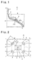
- Fig. 1 is a schematic cross-sectional view showing
the structure of the glass funnel for a cathode ray tube
according to a first embodiment of the present invention;
- Fig. 2 is a schematic front view showing the
structure of the glass funnel for a cathode ray tube
according to the first embodiment of the present
invention;
- Fig. 3 is a schematic perspective view showing the
structure of the glass funnel for a cathode ray tube
according to a second embodiment of the present
invention;
- Fig. 4 is a schematic cross-sectional view showing
the structure of the glass funnel for a cathode ray tube
according to a third embodiment of the present invention;
- Fig. 5 is a schematic perspective view showing the
structure of the glass funnel for a cathode ray tube
according to the third embodiment of the present
invention;
- Fig. 6 is a schematic cross-sectional view showing
the structure of the glass funnel for a cathode ray tube
according to a fourth embodiment of the present
invention;
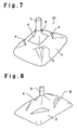
- Fig. 7 is a schematic perspective view showing the
structure of the glass funnel for a cathode ray tube
according to the fourth embodiment of the present
invention;
- Fig. 8 is a schematic perspective view showing the
structure of the glass funnel for a cathode ray tube in
Example 7; and
- Fig. 9 is a schematic cross-sectional view showing
the structure of a conventional glass funnel for a
cathode ray tube.
-
-
In the drawings, reference numeral 1 designates a
glass panel, reference numeral 2 designates a glass
funnel, reference numeral 3 designates a body portion,
reference numeral 4 designates a yoke portion, reference
numeral 5 designates a neck portion, reference numeral 6
designates an electron gun, reference numeral 7
designates a deflection coil, reference numeral 8
designates a projected portion, reference numerals 9 and
9' designate stepped portions, reference numeral 10
designates a sealing portion, reference numeral 12
designates a fluorescent film, reference numeral 13
designates an aluminum film, reference numeral 14
designates a shadow mask, reference numeral 15 designates
a stud pin, reference numeral 16 designates a reinforcing
band, reference numeral 17 designates an anode button,
reference A designates a bulb axis, reference B
designates a reference line, reference C designates a
diagonal axis, reference r designates an outer peripheral
area, reference n designates an intersecting point, and
reference α designates a plane perpendicular to the bulb
axis.
BEST MODE FOR CARRYING OUT THE INVENTION
-
The glass funnel for a cathode ray tube according to
the present invention has a bent portion, such as a
projected portion or a stepped portion, provided at a
specific position of a body portion around a yoke portion
as stated earlier, offering an advantage to suppress an
increase in a tensile stress in the yoke portion caused
by deformation energy in the body portion.
-
In a cathode ray tube, it is normal that the glass
funnel has a neck portion formed at the rearmost position
(the position farthest from a glass panel), a yoke
portion formed so as to be forward of the neck portion,
and a body portion formed so as to be forward of the yoke
portion to connect between the yoke portion and a
glass panel provided on a front side of the glass funnel.
The glass funnel has a depth shorter than the width of an
open end.
-
For this reason, the body portion is strongly
subjected to such a deforming force to be forced in
toward the open end by a pressure difference between the inside
and the outside thereof. As stated earlier, the
deformation energy in the body portion eventually
concentrates at the yoke portion since the yoke portion
is located so as to project toward a central portion of
the body portion.
-
The deformation in the body portion varies among
short side walls, long side walls and diagonal walls
according to the difference among these sections in terms
of area or rigidity. Specifically, the short side walls
are deformed so as to be most forced in, the long side
walls are greatly deformed, and the diagonal walls are
most difficult to be deformed. Under the circumstances,
the body portion is deformed in such a complex way that
the diagonal walls are deformed as if the diagonal walls
are drawn into the long side walls and the short side
walls and that the entire body portion is drawn toward
the short side walls. This complex deformation generates
stresses having a high tensile property (tensile
stresses) in diagonal walls and short side walls of the
yoke portion.
-
In accordance with the present invention, in order
to suppress the tensile stresses in the yoke portion, the
deformation energy in the body portion is controlled
before being transmitted to the yoke portion. By
additionally providing a structure having a high rigidity
(bent portion) to a peripheral wall of the body portion
so as to extend in each of the short side walls and the
long side wall adjacent thereto with the diagonal wall
therebetween being centered the deformation energy to be
transmitted to the yoke portion can be substantially
equalized to level the deformation in the yoke, reducing
the tensile stress. When the bent portion to be provided
around the yoke portion continuously extends on the
entire periphery of the yoke portion, it is possible to
obtain a better effect. The bent portion may be composed
of a curved surface, a combination of plural flat
surfaces or a combination of a curved surface and a flat
surface. For example, by forming the bent portion as a
projected portion or a stepped portion, it is possible to
easily provide a structure having a high rigidity without
increasing the mass or degrading productivity.
-
Now, the glass funnel for a cathode ray tube and the
cathode ray tube according to the present invention will
be described in detail, referring to appropriate
embodiments shown in some of the accompanying drawings.
-
Fig. 1 and Fig. 2 are a schematic cross-sectional
view and a schematic front view showing the structure of
the glass funnel for a cathode ray tube according to a
first embodiment of the present invention, respectively.
-
As shown in Fig. 1, the glass funnel 21 according to
the first embodiment includes a body portion 3 having an
open end formed in a substantially rectangular shape, a
neck portion 5 for housing an electron gun (not shown),
and a yoke portion 4 connecting between the body portion
3 and the neck portion 5. Additionally, the yoke portion
may have a deflection unit (not shown) mounted on an
outer side for deflecting electron beams irradiated from
the electron gun.
-
In Fig. 1 and Fig. 2, projected portions 8 are
provided as bent portions projecting outwardly from the
body portion 3 along some positions of an outer
peripheral area r, where the body portion 3 intersects
with a plane α perpendicular to bulb axis A, and which
include intersecting points n between the outer
peripheral area r and a plane containing a diagonal axis
C and the bulb axis A.
-
In the present invention, the phrase "bulb axis"
means a straight line containing a central axis of the
neck portion and passing through the center of a face
portion. The phrase "diagonal axis" means a diagonal
line of the open end formed in a substantially
rectangular shape in the body portion.
-
In the first embodiment shown in Fig. 1 and Fig. 2,
the projected portions 8 are not provided on the entire
periphery of the outer peripheral area r, and each of the
projected portions is provided so as to extend in a short
side wall and a long side wall adjacent thereto with the
diagonal wall n therebetween being centered. In this
embodiment, it was revealed by the numerical experiment
based on a finite element method conducted by the
inventor that when the sum of the lengths of the
projected portions along the outer peripheral area r was
not less than 1/4 of the length of the outer peripheral
area r, it was possible to have a significant effect of
avoiding deformation caused by, in particular, generation
of tensile stresses. From this viewpoint, it is
preferable that the sum of the lengths of the bent
portions is not less than 1/4 of the length of the outer
peripheral area.
-
The positions of the projected portions 8 satisfy
the formula of L/D≤1/2, wherein the distance between the
boundary between the body portion 3 and the yoke portion
4, and each of the projected portions 8, and the distance
between the boundary between the body portion 3 and the
yoke portion 4, and the open end are L and D in terms of
components in each of the relevant diagonal directions,
respectively, on the plane containing the relevant
diagonal axis C and the bulb axis A. The projected
portions 8 may be positioned at desired locations in the
range satisfying the formula, considering the purpose of
design or the positions of other parts.
-
When a single projected portion 8 is provided on the
entire periphery of the outer peripheral area r, the
projected portion 8 and its surrounding portions are
configured to have a substantially equal thickness. When
discontinuous projected portions 8 are provided around
the outer peripheral area r, each of the projected
portions 8 and other portions in the same cross-section
perpendicular to the bulb axis are configured to have a
substantially equal glass thickness. In other words, one
of the features of the present invention is that the
single projection or the discontinuous projected portions
are configured to have a hollow space without having a
greater thickness.
-
When the projected portion or portions are provided
so as to have a greater thickness as disclosed in JP-Y-57-518,
the mass of the glass funnel significantly
increases. Additionally, the projected portion or
portions having a greater thickness and surrounding
portions thereof have different heat capacities because
of the difference in volume, the projected portion or
portions and the surrounding portions thereof behave in
different ways in terms of expansion, shrinkage or the
like in a thermal process, and, consequently, stresses
(thermal stresses) are generated, causing a crack
(fracture).
-
Conversely, when the projected portion or portions 8
and the surrounding portions thereof are configured to
have a substantially equal thickness as in the present
invention, it is possible to prevent thermal stresses
from causing a crack.
-
Additionally, in accordance with the present
invention, it is possible to provide the glass funnel
with a fracture prevention structure without an increase
in mass since the projected portion or portions 8 and the
surrounding portions thereof are configured to have a
substantially equal thickness.
-
In the first embodiment, the projected portions 8
provided in the body portion 3 are projected portions
having a substantially semicircular shape (arched shape)
in section as shown in Fig. 1. In the present invention,
the projected portions are not limited to have a
semicircular shape in section. The projected portions
may have any desired shape according to the purpose of
design or production capacity as long as the shape is
helpful to improve rigidity against bending in the
direction of the bulb axis.
-
It is preferable that the projected portion or
portions have a height H1 of 5 to 50 mm. When the height
of the projected portion or portions is included in this
range, it is possible to increase the effect of
preventing tensile stresses from being generated in the
yoke portion. It is more preferable that the height H1
is 10 to 30 mm.
-
The "height of the projected portion or portions" is
measured in the direction of a normal line of a section
of the body portion close to a projected portion in the
plane containing the diagonal axis and the bulb axis.
-
The number of the projected portion or portions 8
may be one or more in the plane containing a diagonal
axis C and the bulb axis A.
-
There may be bent portions, which are not located at
the intersection n between a plane containing a diagonal
axis C and the bulb axis A and the outer peripheral areas
r.
-
As shown in Fig. 2, the glass funnel according to
the first embodiment is a glass funnel, where the yoke
portion has a substantially rectangular cross-section
perpendicular to the bulb axis.
-
Although the glass funnel according to the present
invention may have the yoke portion formed in any shape,
the provision of the bent portion or portions is
particularly effective when the yoke portion has a
substantially rectangular cross-section perpendicular to
the bulb axis. This is because this shape of yoke
portion has different rigidities in different directions.
-
When the yoke portion has a substantially
rectangular cross-section perpendicular to the bulb axis,
the yoke portion is influenced directly by the
deformation in the body portion since the yoke portion
has a similar structure to the body portion. Accordingly,
this shape of yoke portion is apt to have greater tensile
stresses than yoke portions having another cross-section.
From this viewpoint as well, the provision of the bent
portion or portions is significantly effective.
-
Fig. 3 is a schematic perspective view showing the
structure of the glass funnel for a cathode ray tube
according to a second embodiment of the present invention.
Explanation of the second embodiment will be made,
focusing on different features from the first embodiment,
and explanation of similar features to the first
embodiment will be omitted.
-
In the second embodiment, as shown in Fig. 3, the
glass funnel 22 includes a yoke portion 4 having a
circular cross-section perpendicular to the bulb axis,
and a single projected portion 8 is provided on the
entire periphery of an outer peripheral area of a body
portion 3 close to the yoke portion 4. When the
projected portion 8 is seen from a direction of the bulb
axis, the projected portion is formed in such a shape
between a circular shape and a rectangular shape so as to
correspond to the shape of the outer peripheral area of
the body portion, where the projected portion is provided.
The glass funnel according to the second embodiment has a
cross-section containing the bulb axis and a diagonal
axis formed in a similar shape to the first embodiment
shown in Fig. 1. In other words, the glass funnel
according to the second embodiment has the projected
portion formed in a semi-circular shape as the bent
portion.
-
Fig. 4 and Fig. 5 are a schematic cross-sectional
view and a schematic perspective view showing the
structure of the glass funnel for a cathode ray tube
according to a third embodiment of the present invention,
respectively. Explanation of the third embodiment will
be made, focusing on different features from the first
embodiment and the second embodiment, and explanation of
similar features to the first and second embodiments will
be omitted.
-
The glass funnel 23 according to the third
embodiment has a stepped portion 9 provided on the entire
periphery of an outer peripheral area of a body portion 3
close to a yoke portion 4.
-
In Fig. 4 and Fig. 5, the stepped portion 9 has a
rectangular shape when being seen from a direction of the
bulb axis. The stepped portion may have another shape,
such as a circumferential shape. The stepped portion may
have any shape as long as the stepped portion is provided
so as to extend in a long side wall and a short side wall
adjacent thereto with the diagonal wall therebetween
being centered. The shape of the stepped portion may be
selected, considering the purpose of design or
productivity.
-
It is preferable that the stepped portion has a
height H2 of 5 to 50 mm. When the height of the stepped
portion is included in this range, it is possible to
increase the effect of preventing tensile stresses from
being generated in the yoke portion. When the stepped
portion is discontinuously provided around the outer
peripheral area of the body portion, the height H2 is
preferably 10 to 40 mm, more preferably 10 to 30 mm.
-
The "height of the stepped portion" is measured in a
direction of the bulb axis in the plane containing a
diagonal axis and the bulb axis.
-
Fig. 6 and Fig. 7 are a schematic cross-sectional
view and a schematic perspective view showing the
structure of the glass funnel for a cathode ray tube
according to a fourth embodiment of the present invention.
Explanation of the fourth embodiment will be made,
focusing on different features from the first embodiment,
and the second embodiment and the third embodiment, and
explanation of similar features to the first to third
embodiments will be omitted.
-
The glass funnel 24 according to the fourth
embodiment has stepped portions 9' provided therein so
that each of the stepped portions extend in a short side
wall and a long side wall adjacent thereto with the
diagonal wall therebetween being centered, without being
continuously provided on the entire periphery of the
outer peripheral area.
-
Each of the stepped portions 9' according to the
fourth embodiment is configured so as to be raised on the
side close to a body portion 3 and lowered on the side
close to a yoke portion 4 in the cross-section containing
the bulb axis A and a diagonal axis C, which is opposite
to the stepped portion 9 according to the third
embodiment. Both stepped portions according to the
fourth embodiment and stepped portion according to the
third embodiment can enjoy the advantage of the present
invention.
-
Although the glass funnel for a cathode ray tube
according to the present invention has been described
based on the respective embodiments shown, the present
invention is not limited to these embodiments. For
example, the structure of each of the parts may be
substituted by another structure capable of performing a
similar function.
-
Although explanation of the embodiments has been
made about a case wherein a projected portion or a
stepped portion is provided as the bent portion, the
present invention is not limited to such a case. The
present invention may use a combination of a projected
portion and a stepped portion, or use another structure
capable of performing a similar function.
-
The glass funnel according to the present invention
is extremely effective since it is possible to realize a
decrease in tensile stresses caused in the yoke portion
and a reduction in weight without significantly modifying
the structure of a conventional glass funnel as stated
earlier and since it is possible to put the present
invention into practice in an extremely simple fashion
and to have a high degree of freedom in design.
-
The cathode ray tube according to the present
invention is applicable to any kinds of cathode ray tube
as long as the glass funnel for a cathode ray tube
according to the present invention is used. Specifically,
the cathode ray tube may be composed of, e.g. a glass
bulb wherein the glass funnel for a cathode ray tube
according to the present invention is combined with a
conventional glass panel.
-
The cathode ray tube according to the present
invention is difficult to be fractured, is lightweight
and easy to be produced since the glass funnel for a
cathode ray tube according to the present invention is
used.
-
Although the present invention will be specifically
explained by showing examples, the present invention is
not limited to the examples.
-
Glass panels for 32-inch TV broadcast receivers,
which had an aspect ratio of 16:9 and an effective screen
with a diagonal size of 76 cm, and the glass funnels in
Examples 1 to 6 and Comparative Examples 1 to 3 stated
below, which had different dimensions and shapes, were
sealed in pairs and evacuated. A strain gauge KFG-5-120-D16-11
manufactured by KYOWA ELECTRONIC INSTRUMENTS CO.,
LTD. was affixed to the respective yoke portions to
measure the maximum tensile stress therein. The glass
materials used for the respective parts are listed in
Table 1 (all manufactured by Asahi Glass Company,
Limited).
-
The mass and the dimensions of each of the
respective glass funnels, and the maximum tensile stress
of each of the yoke portions are shown in Table 2. The
glass funnels in the examples and the comparative
examples had a deflection angle of 120°C.
| Glass | Panel glass | Funnel glass | Neck glass |
| Name (brand name) | 5008 | 0138 | 0150 |
| Density (g/cm3) | 2.79 | 3.00 | 3.29 |
| Young's modulus (GPa) | 75 | 69 | 62 |
| Poisson's ratio | 0.21 | 0.21 | 0.23 |
| Softening point (°C) | 703 | 663 | 643 |
| Annealing point (°C) | 521 | 491 | 466 |
| Strain point (°C) | 477 | 453 | 428 |
EXAMPLE 1
-
A glass funnel having a projected portion provided
around the entire periphery of the outer peripheral area
as shown in Fig 3.
EXAMPLE 2
-
A glass funnel similar to Example 1 except that the
thickness of the projected portion and the thickness of
the body portion were set as listed in Table 2.
EXAMPLE 3
-
A glass funnel having a projected portion
discontinuously provided around the outer peripheral area
as shown in Fig. 1 and Fig. 2.
EXAMPLE 4
-
A glass funnel having a stepped portion provided
around the entire periphery of the outer peripheral area
as shown in Fig. 4 and Fig. 5.
EXAMPLE 5
-
A glass funnel similar to Example 4 except that the
total length of the stepped portion along the outer
peripheral area was 3/10 of the entire length of the
outer peripheral area.
EXAMPLE 6
-
A glass funnel similar to Example 4 except that the
total length of the stepped portion along the outer
peripheral area was 4/10 of the entire length of the
outer peripheral area.
EXAMPLE 7
-
Example 7 represents another embodiment based on the
technical idea of the funnel shown in each of Example 5
and Example 6 and has the shape shown in Fig. 8.
Specifically, this example is a case wherein the stepped
portion was discontinuously provided so that each of the
discontinuous sections of the stepped portion extends in
a short side wall of the body portion and a long side
wall of the body portion adjacent thereto with the
diagonal wall therebetween being centered, without being
continuously provided on the entire periphery of the
outer peripheral area. The stepped portion is configured
so as to be lowered on the side close to the open end of
the body portion 3 (to be farther from the neck portion)
and raised on the side close to the yoke portion 4 (to be
closer to the neck portion) as shown in Fig. 8, which is
similar to the stepped portion 9 in the third embodiment.
The height H2 of the projected portion was 35 mm, and the
length of the stepped portion was 3/10 of the entire
length of the outer peripheral area.
EXAMPLE 8
-
A glass funnel similar to Example 7 except that the
height H2 of the stepped portion was 25 mm and that the
total length of the stepped portion is 7/10 of the entire
length of the outer peripheral area.
COMPARATIVE EXAMPLE 1
-
A glass funnel wherein no bent portion was provided,
and the yoke portion had a circular cross-section
perpendicular to the bulb axis.
COMPARATIVE EXAMPLE 2
-
A glass funnel wherein no bent portion was provided,
and the yoke portion had a substantially rectangular
cross-section perpendicular to the bulb axis.
COMPARATIVE EXAMPLE 3
-
A glass funnel similar to Comparative Example 2
except that the thickness of the body portion and the
thickness of the yoke portion were set as listed in Table
2.
-
As clearly seen from Table 2, the glass funnel in
Example 1 as an example of the glass funnel for a cathode
ray tube according to the present invention was able to
reduce the tensile stress in the yoke portion by 40% in
comparison with the glass funnel in Comparative Example 1,
which had the respective parts set at the same dimensions.
-
In the glass funnel in Example 2 as an example of
the glass funnel for a cathode ray tube according to the
present invention, an attempt was made to reduce the
thickness of the projected portion and the thickness of
the body portion so as to realize a reduction in weight,
taking advantage of the reduction in the tensile stress
in the yoke portion of the glass funnel in Example 1.
Example 2 was able to reduce the mass by about 7% in
comparison with Comparative Example 1 without the tensile
stress in the yoke portion being substantially changed in
comparison with the case of Example 1.
-
The glass funnel in Example 3 as an example of the
glass funnel for a cathode ray tube according to the
present invention was able to reduce the tensile stress
in the yoke portion by 33% in comparison with the glass
funnel in Comparative Example 2, which had the respective
parts set at the same dimensions.
-
It is seen that the glass funnel in Example 4 as an
example of the glass funnel for a cathode ray tube
according to the present invention has an excellent
balance between the reduction in the tensile stress in
the yoke portion and the reduction in the mass in
comparison with the glass funnels in Comparative Examples
1 to 3, which had the respective parts set at the same
dimensions.
-
The glass funnels in Example 5 and Example 6 as
examples of the glass funnel for a cathode ray tube
according to the present invention is different from
Example 4 in that the stepped portion is discontinuously
provided. Each of Example 7 and Example 8 represents
another embodiment based on the technical idea of the
funnel shown in Example 5 and Example 6. It is seen that
the tensile stress in the yoke portion of the funnel in
each of Examples 5 to 8 is not almost different from that
in Example 4, and that the funnel in each of Examples 5
to 8 has an excellent balance between the reduction in
the tensile stress in the yoke portion and the reduction
in the mass in comparison with the glass funnels in
Comparative Examples 1 to 3, which had the respective
parts set at almost the same dimensions.
-
On the other hand, the glass funnel in each of
Comparative Example 1 and Comparative Example 2, each of
which is directed to a conventional glass funnel for a
cathode ray tube having no bent portion (neither a
projected portion nor a stepped portion), cannot be put
to use since the yoke portion is subjected to a high
tensile stress and has a low reliability.
-
The glass funnel in Comparative Example 3 as a
conventional glass funnel for a cathode ray tube, wherein
the body portion has a greater thickness instead of
having a bent portion in order to minimize the tensile
stress in the yoke portion, is heavy in mass.
INDUSTRIAL APPLICABILITY
-
The glass funnel according to the present invention
is difficult to be fractured since the body portion can
have the bent portion provided therein to reduce the
tensile stresses caused in the yoke portion. The glass
funnel according to the present invention is lightweight
since the glass thickness in the body portion or the yoke
portion does not increase. The glass funnel according to
the present invention can be produced by an extremely
simple method. The glass funnel according to the present
invention needs to significantly modify the composition
and the structure of a conventional glass funnel.
-
In accordance with the present invention, it is
possible to provide a glass funnel and a cathode ray
tube, which are capable of being safe, highly reliable
and lightweight.