EP1443528A2 - Super conductive magnet apparatus - Google Patents
Super conductive magnet apparatus Download PDFInfo
- Publication number
- EP1443528A2 EP1443528A2 EP04000435A EP04000435A EP1443528A2 EP 1443528 A2 EP1443528 A2 EP 1443528A2 EP 04000435 A EP04000435 A EP 04000435A EP 04000435 A EP04000435 A EP 04000435A EP 1443528 A2 EP1443528 A2 EP 1443528A2
- Authority
- EP
- European Patent Office
- Prior art keywords
- super conductive
- magnet apparatus
- support body
- conductive magnet
- connecting member
- Prior art date
- Legal status (The legal status is an assumption and is not a legal conclusion. Google has not performed a legal analysis and makes no representation as to the accuracy of the status listed.)
- Granted
Links
- 239000001307 helium Substances 0.000 claims abstract description 64
- 229910052734 helium Inorganic materials 0.000 claims abstract description 64
- SWQJXJOGLNCZEY-UHFFFAOYSA-N helium atom Chemical compound [He] SWQJXJOGLNCZEY-UHFFFAOYSA-N 0.000 claims abstract description 64
- 239000007788 liquid Substances 0.000 claims abstract description 41
- 229910000963 austenitic stainless steel Inorganic materials 0.000 claims description 8
- 238000002595 magnetic resonance imaging Methods 0.000 claims description 6
- XAGFODPZIPBFFR-UHFFFAOYSA-N aluminium Chemical compound [Al] XAGFODPZIPBFFR-UHFFFAOYSA-N 0.000 claims description 4
- 229910052782 aluminium Inorganic materials 0.000 claims description 4
- 230000005540 biological transmission Effects 0.000 description 3
- 230000007423 decrease Effects 0.000 description 3
- 239000007789 gas Substances 0.000 description 3
- 239000012212 insulator Substances 0.000 description 2
- 239000000463 material Substances 0.000 description 2
- 238000007789 sealing Methods 0.000 description 2
- 229910000838 Al alloy Inorganic materials 0.000 description 1
- 238000005452 bending Methods 0.000 description 1
- 239000011230 binding agent Substances 0.000 description 1
- 230000006835 compression Effects 0.000 description 1
- 238000007906 compression Methods 0.000 description 1
- 238000001816 cooling Methods 0.000 description 1
- 230000003247 decreasing effect Effects 0.000 description 1
- 238000001704 evaporation Methods 0.000 description 1
- 230000008020 evaporation Effects 0.000 description 1
- 230000004907 flux Effects 0.000 description 1
- 239000003365 glass fiber Substances 0.000 description 1
- 239000004519 grease Substances 0.000 description 1
- 238000002347 injection Methods 0.000 description 1
- 239000007924 injection Substances 0.000 description 1
- 230000004048 modification Effects 0.000 description 1
- 238000012986 modification Methods 0.000 description 1
- 230000005855 radiation Effects 0.000 description 1
- 239000010935 stainless steel Substances 0.000 description 1
- 229910001256 stainless steel alloy Inorganic materials 0.000 description 1
- 238000003466 welding Methods 0.000 description 1
Images


Classifications
-
- H—ELECTRICITY
- H01—ELECTRIC ELEMENTS
- H01F—MAGNETS; INDUCTANCES; TRANSFORMERS; SELECTION OF MATERIALS FOR THEIR MAGNETIC PROPERTIES
- H01F6/00—Superconducting magnets; Superconducting coils
-
- G—PHYSICS
- G01—MEASURING; TESTING
- G01R—MEASURING ELECTRIC VARIABLES; MEASURING MAGNETIC VARIABLES
- G01R33/00—Arrangements or instruments for measuring magnetic variables
- G01R33/20—Arrangements or instruments for measuring magnetic variables involving magnetic resonance
- G01R33/28—Details of apparatus provided for in groups G01R33/44 - G01R33/64
- G01R33/38—Systems for generation, homogenisation or stabilisation of the main or gradient magnetic field
- G01R33/381—Systems for generation, homogenisation or stabilisation of the main or gradient magnetic field using electromagnets
- G01R33/3815—Systems for generation, homogenisation or stabilisation of the main or gradient magnetic field using electromagnets with superconducting coils, e.g. power supply therefor
-
- H—ELECTRICITY
- H01—ELECTRIC ELEMENTS
- H01F—MAGNETS; INDUCTANCES; TRANSFORMERS; SELECTION OF MATERIALS FOR THEIR MAGNETIC PROPERTIES
- H01F6/00—Superconducting magnets; Superconducting coils
- H01F6/04—Cooling
-
- H—ELECTRICITY
- H01—ELECTRIC ELEMENTS
- H01F—MAGNETS; INDUCTANCES; TRANSFORMERS; SELECTION OF MATERIALS FOR THEIR MAGNETIC PROPERTIES
- H01F6/00—Superconducting magnets; Superconducting coils
- H01F6/06—Coils, e.g. winding, insulating, terminating or casing arrangements therefor
Definitions
- the present invention relates to a super conductive magnet apparatus, and a magnetic resonance imaging machine including the super conductive magnet apparatus.
- a super conductive magnet is contained by a container while a space between the super conductive magnet and the container is filled with a liquid helium, and the container is supported on a vessel through connecting members.
- An object of the present invention is to provide a super conductive magnet apparatus, and a magnetic resonance imaging machine including the super conductive magnet apparatus, in which apparatus a super conductive magnet is effectively cooled by liquid helium, and/or thermal energy is restrained from being applied to the super conductive magnet from the outer environment of the super conductive magnet apparatus.
- a super conductive magnet apparatus comprising: a super conductive coil, a helium containing volume or vessel for containing therein liquid helium to keep the temperature of the super conductive coil low, and a vacuum vessel containing therein the super conductive coil and the helium containing volume.
- the super conductive magnet apparatus further comprises a support body on which the super conductive coil is arranged, a container cover forming the helium containing volume with the support body in such a manner that thermal energy is capable of being transmitted between the super conductive coil and the liquid helium, and a connecting member connecting the support body to the vacuum vessel so that the support body is supported through the connecting member on the vacuum vessel, the connecting member (preferably having at least partially a bar-shape) restrains effectively the thermal transmission between the support body and the outer environment of the super conductive magnet apparatus.
- the super conductive coil is capable of generating a magnetic force in such a manner that a tensile stress is generated longitudinally in the connecting member by the magnetic force while the super conductive coil is prevented from generating the magnetic force in such a manner that a compressive stress is generated longitudinally in the connecting member by the magnetic force, a cross sectional area of the connecting member may be minimized, because the connecting member does not need to have a strength and/or rigidity against a compression buckling thereof.
- the connecting member extends through the liquid helium in the containing volume, and/or the connecting member extends through the container cover to the vacuum vessel, the connecting member is effectively cooled by the liquid helium or the thermal energy supplied from the outer environment to the connecting member is effectively absorbed by the liquid helium, so that the super conductive magnet is effectively cooled by the liquid helium, and/or the thermal energy is restrained from being applied to the super conductive magnet through the connecting member from the outer environment of the super conductive magnet apparatus.
- the connecting member includes a monolithic part thereof extending through the container cover from an inner side of the container cover contacting the liquid helium to a vacuum outer side of the container cover, a hermetic sealing between the monolithic part of the connecting member and the container cover can be securely maintained, and a contact area between the monolithic part of the connecting member and the container cover can be minimized.
- the thermal energy is capable of being transmitted through the support body between the super conductive coil and the liquid helium while the liquid helium is prevented from contacting the super conductive coil, the hermetic sealing of the liquid helium is easily maintained, because an electric power supply to the super conductive coil does not need to extend through the container cover.
- the thermal energy is capable of being transmitted between the super conductive coil and the liquid helium contacting the super conductive coil, the super conductive coil can be effectively cooled by a direct contact between the super conductive coil and the liquid helium.
- the super conductive coil may be wound on the support body.
- the super conductive magnet apparatus may further comprise a shield surrounding the super conductive coil and the helium containing volume, which is surrounded by the vacuum vessel.
- the shield may include one of aluminum or austenitic stainless steel as a main component thereof.
- the super conductive magnet apparatus may comprise a pair of the super conductive coils, one of which is surrounded by the other one as seen in the common axial direction of the super conductive coils. If the connecting member extends between the super conductive coils as seen in the common axial direction of the super conductive coils, a bending or rotational moment is restrained from being generated by the magnetic forces of the super conductive coils, particularly when directions of the magnetic forces of the super conductive coils are equal to each other.
- the support body includes first and second support body parts on which the super conductive coils are respectively wound, and the first and second support body parts are discrete from each other to be separable from each other. If the first and second support body parts have respective surfaces facing to each other in a transverse direction perpendicular to the common axial direction in such a manner that the first and second support body parts are capable of being positioned with respect to each other in the transverse direction by a contact between the surfaces, the first and second support body parts can be positioned correctly with respect to each other in the transverse direction.
- first and second support body parts are separable from each other along and/or from at least one face extending in a transverse direction perpendicular to the common axial direction, the first and second support body parts can be positioned correctly with respect to each other in the common axial direction.
- a part of the connecting member extending through the liquid helium includes austenitic stainless steel as a main component thereof, the magnetic field of the super conductive coil is restrained from being deteriorated by the connecting member.
- the support body has a fluidal path fluidly communicating with the helium containing volume and covered by a part the connecting member so that the part the connecting member is fluidly communicating with the helium containing volume, the thermal energy supplied from the outer environment to the connecting member is effectively absorbed by the liquid helium, and/or the thermal energy is restrained from being applied to the super conductive magnet through the connecting member from the outer environment of the super conductive magnet apparatus, even when the connecting member is prevented from extending through the liquid helium and/or the container cover.
- a magnetic resonance imaging machine may comprises the super conductive magnet apparatus according to the present invention.
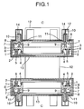
- main coils 1 of a super conductive magnet are wound on respective coil frames 2.
- Support bodies 3 are formed of (preferably austenitic) stainless steel or aluminum alloy, and include respective coil frames 2 of respective sub-coils 4 of the super conductive magnet surrounded respectively by the main coils 1 coaxially.
- Two pairs of the main coils 1 and coil frames 2 are stacked vertically to form a space therebetween in such a manner that a patient can be inserted in the space in which a high and constant density magnetic field is generated by the super conductive magnet.
- the coil frames 2 of the main coils 1 are detachably mounted with binders 5 and bolts 6 onto the support bodies 3 forming the coil frames of the sub-coils 4.
- Volume 7 formed by the support bodies 3 and covers 8 are filled with a liquid helium to cool the main coils 1 and sub-coils 4.
- each of the support bodies 3 is supported on a vacuum vessel 12 through twelve connecting members including respective support members 9 (preferably made of austenitic stainless steel) in liquid and low temperature support elements 10 (preferably made of austenitic stainless steel or a plastic reinforced by glass fiber).
- Ends of the support members 9 are connected to the support bodies 3 and the other ends thereof are connected to the covers 8 by welding.
- Ends of the low temperature support elements 10 are connected to the other ends of the support members 9 through mounting members 11, and the other ends of the low temperature support elements 10 are connected to the vacuum vessel 12.
- a shield 13 surrounds the covers 8, support members 9, support bodies 3, main coils 1, sub-coils 4, and parts of the low temperature support elements 10, and is formed of a low thermal radiation characteristic material, such as aluminum or the like.
- the shield 13 may be covered by a thermal insulator sheet (not shown) formed of stacked films on whose outer surfaces aluminum is deposited to restrain a radiant energy from being transmitted into the thermal insulator sheet.
- the low temperature support elements 10 are connected to the shield 13 through thermal anchors 14 for keeping a high thermal transmission therebetween so that a temperature of the low temperature support elements 10 is kept low to restrain a thermal transmission between the low temperature support elements 10 and the liquid helium.
- magnetic shields 25 including a magnetically permeable material may be arranged respectively on upper and lower sides of the vacuum vessel 12 to cover the coils so that a magnetic flux is prevented from leaking from the super conductive magnet to an undesired area.
- the detachable coil frame for main coils 1 or sub-coils 4 may be omitted, and the support bodies 3 may have support body parts on which the coils are not wound and coil frames on which the coils are wound while the support body parts are separable from the coil frames.
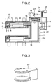
- a reservoir 15 stores the liquid helium
- a connecting pipe 16 connects fluidly the reservoir 15 to the volume 7 formed by the support bodies 3 and covers 8.
- An injection port 17 allows the liquid helium to be supplied into the reservoir 15, and a discharge valve 18 allows the helium to be discharged to the atmosphere.
- a helium refrigerating machine has a high temperature stage 19 having refrigerating capacity of 70 ,W at about 70 Kelvin and a low temperature stage 20 having refrigerating capacity of 1 W at about 4 Kelvin.
- a heat exchanger 22 cooled by the low temperature stage 20 absorbs a heat energy from a helium gas in the reservoir 15 to liquefy the helium.
- the high temperature stage 19 absorbs the heat energy from the shield 13 to be cooled.
- a gas pipe 23 extends from an upper region of the reservoir 15 to the atmosphere outside of the vacuum vessel 12 with thermal contact with the shield 13 surrounding the reservoir 15 so that an evaporation of the liquid helium in the gas pipe 23 extending to the atmosphere cools the shield 13 when the helium refrigerating machine is stopped.
- a check valve 24 prevents the atmosphere from flowing into the reservoir 15 when the helium refrigerating machine is operated to decrease a pressure in the reservoir 15.
- the liquid helium cooled and liquefied in the reservoir 15 is evaporated by the support bodies 3, main coils 1 and/or sub-coils 4 so that temperatures of the main coils 1 and sub-coils 4 are kept less than critical temperatures thereof to operate the main coils 1 and sub-coils 4 stably.
- the evaporated helium is again cooled and liquefied in the reservoir 15 so that the helium does not need to be supplied into the reservoir 15.
- the shield 13 cooled at 40-80 Kelvin by the high temperature stage 19 decreases a thermal conduction between the connecting members and the liquid helium.
- the coil frames of the main coils 1 and sub-coils 4 may be joined with the support bodies 3 through screw engagements 26.
- a pair of the support body 3 and the coil frame 2 may have recess and protrusion engagement between the support body 3 and coil frame 2 so that the support body 3 and coil frame 2 are positioned correctly with respect to each other, and a contact area for thermal conductivity therebetween is increased.
- the main coils 1 and sub-coils 4 may contact the liquid helium.
- the low temperature support elements 10 are fixed to the support bodies 3 through attachments 11 fixed to the support bodies 3 by bolts.
- the support members 9 may extend through the volume in which the main coils 1 and sub-coils 4 contact the liquid helium.
- the connecting members extending between the support bodies 3 and the vacuum vessel is prevented from extending through the liquid helium, it is preferable for keeping the temperature of the connecting members low to restrain the thermal conduction between the connecting members and the main coils 1 and sub-coils 4 that the connecting members or attachments 11 may contact the liquid helium through liquid helium passages 31 extending through the support bodies 3.
Landscapes
- Physics & Mathematics (AREA)
- Electromagnetism (AREA)
- Condensed Matter Physics & Semiconductors (AREA)
- General Physics & Mathematics (AREA)
- Engineering & Computer Science (AREA)
- Power Engineering (AREA)
- Magnetic Resonance Imaging Apparatus (AREA)
- Containers, Films, And Cooling For Superconductive Devices (AREA)
Abstract
Description
Claims (20)
- A super conductive magnet apparatus comprising,
a super conductive coil (1, 4),
a helium containing volume (7) for containing therein liquid helium to keep a temperature of the super conductive coil (1, 4) low, and
a vacuum vessel (12) containing therein the super conductive coil (1, 4) and the helium containing volume (7),
wherein the super conductive magnet apparatus further comprises a support body (3) on which the super conductive coil (1, 4) is arranged, a container cover (8) forming the helium containing volume (7) with the support body (3) in such a manner that thermal energy is capable of being transmitted between the super conductive coil (1, 4) and the liquid helium, and a connecting member (9, 11) connecting the support body (3) to the vacuum vessel (12) so that the support body (3) is supported through the connecting member (9, 11) on the vacuum vessel (12). - A super conductive magnet apparatus according to claim 1, wherein the super conductive coil (1, 4) is capable of generating a magnetic force in such a manner that a tensile stress is generated longitudinally in the connecting member (9, 11) by the magnetic force.
- A super conductive magnet apparatus according to any one of claims 1 and 2, wherein the connecting member (9, 11) extends through the liquid helium in the helium containing volume (7).
- A super conductive magnet apparatus according to any one of claims 1-3, wherein the connecting member (9, 11) extends through the container cover (8) to the vacuum vessel (12).
- A super conductive magnet apparatus according to claim 4, wherein the connecting member (9, 11) includes a monolithic part thereof extending between inside and outside of the container cover (8).
- A super conductive magnet apparatus according to any one of claims 1-5, wherein the thermal energy is capable of being transmitted through the support body (3) between the super conductive coil (1, 4) and the liquid helium while the liquid helium is prevented from contacting the super conductive coil (1,4).
- A super conductive magnet apparatus according to any one of claims 1-5, wherein the thermal energy is capable of being transmitted between the super conductive coil(1, 4) and the liquid helium contacting the super conductive coil (1, 4).
- A super conductive magnet apparatus according to any one of claims 1-7, wherein the super conductive coil (1, 4) is wound on the support body (3).
- A super conductive magnet apparatus according to any one of claims 1-8, further comprising a shield (13) surrounding the super conductive coil (1, 4) and the helium containing volume (7), and surrounded by the vacuum vessel (12).
- A super conductive magnet apparatus according to claim 9, wherein the shield (13) includes one of aluminum and austenitic stainless steel as a main component thereof.
- A super conductive magnet apparatus according to any one of claims 1-10, wherein the super conductive magnet apparatus comprises a pair of the super conductive coils (1, 4) one of which super conductive coils is surrounded by the other one of the super conductive coils as seen in a common axial direction of the super conductive coils (1, 4).
- A super conductive magnet apparatus according to claim 11, wherein the connecting member (9, 11) extends between the super conductive coils (1, 4) as seen in the common axial direction of the super conductive coils (1, 4).
- A super conductive magnet apparatus according to claim 11, wherein the super conductive coils (1, 4) overlap each other at least partially as seen in a transverse direction perpendicular to the common axial direction.
- A super conductive magnet apparatus according to claim 11, wherein the support body (3) includes first and second support body parts (2, 3) on which the super conductive coils (1, 4) are respectively wound, and the first and second support body parts (2, 3) are discrete from each other to be separable from each other.
- A super conductive magnet apparatus according to claim 14, wherein the first and second support body parts (2, 3) have respective surfaces facing to each other in a transverse direction perpendicular to the common axial direction in such a manner that the first and second support body parts (2, 3) are capable of being positioned with respect to each other in the transverse direction by a contact between the surfaces.
- A super conductive magnet apparatus according to claim 14, wherein the first and second support body parts (2, 3) are separable from each other along at least one face extending in a transverse direction perpendicular to the common axial direction.
- A super conductive magnet apparatus according to claim 3, wherein a part of the connecting member (9, 11) extending through the liquid helium includes austenitic stainless steel as a main component thereof.
- A super conductive magnet apparatus according to any one of claims 1-17, wherein the support body (3) has a fluidal path (31) fluidly communicating with the helium containing volume (7) and covered by a part of the connecting member (10, 11) so that the part the connecting member (10, 11) is fluidly communicating with the helium containing volume (7).
- A super conductive magnet apparatus according to any one of claims 1-18, wherein the support body (3) includes austenitic stainless steel as a main component thereof.
- A magnetic resonance imaging machine comprising the super conductive magnet apparatus according to any one of claims 1-19.
Applications Claiming Priority (2)
| Application Number | Priority Date | Filing Date | Title |
|---|---|---|---|
| JP2003021294 | 2003-01-30 | ||
| JP2003021294A JP4186636B2 (en) | 2003-01-30 | 2003-01-30 | Superconducting magnet |
Publications (3)
| Publication Number | Publication Date |
|---|---|
| EP1443528A2 true EP1443528A2 (en) | 2004-08-04 |
| EP1443528A3 EP1443528A3 (en) | 2004-08-18 |
| EP1443528B1 EP1443528B1 (en) | 2007-09-19 |
Family
ID=32652883
Family Applications (1)
| Application Number | Title | Priority Date | Filing Date |
|---|---|---|---|
| EP04000435A Expired - Lifetime EP1443528B1 (en) | 2003-01-30 | 2004-01-12 | Super conductive magnet apparatus |
Country Status (4)
| Country | Link |
|---|---|
| US (1) | US6864770B2 (en) |
| EP (1) | EP1443528B1 (en) |
| JP (1) | JP4186636B2 (en) |
| DE (1) | DE602004008978T2 (en) |
Cited By (1)
| Publication number | Priority date | Publication date | Assignee | Title |
|---|---|---|---|---|
| GB2545735A (en) * | 2015-12-24 | 2017-06-28 | Siemens Healthcare Ltd | Cryostats for superconducting magnets |
Families Citing this family (45)
| Publication number | Priority date | Publication date | Assignee | Title |
|---|---|---|---|---|
| EP3557956A1 (en) | 2004-07-21 | 2019-10-23 | Mevion Medical Systems, Inc. | A programmable radio frequency waveform generator for a synchrocyclotron |
| JP4661189B2 (en) * | 2004-09-01 | 2011-03-30 | 株式会社日立製作所 | Superconducting magnet device and MRI apparatus and NMR analyzer equipped with the superconducting magnet device |
| JP2006141655A (en) * | 2004-11-19 | 2006-06-08 | Hitachi Ltd | Superconducting magnet apparatus and magnetic resonance imaging apparatus using the same |
| GB0505903D0 (en) * | 2005-03-23 | 2005-04-27 | Siemens Magnet Technology Ltd | A cryogen tank for cooling equipment |
| JP4404021B2 (en) * | 2005-06-30 | 2010-01-27 | 株式会社日立製作所 | Superconducting magnet for MRI |
| ES2730108T3 (en) * | 2005-11-18 | 2019-11-08 | Mevion Medical Systems Inc | Radiation therapy of charged particles |
| JP4705528B2 (en) * | 2006-01-05 | 2011-06-22 | 株式会社日立製作所 | Superconducting magnet apparatus and magnetic resonance imaging apparatus |
| JP4703408B2 (en) * | 2006-01-13 | 2011-06-15 | 三菱電機株式会社 | Superconducting magnet system |
| US7656258B1 (en) * | 2006-01-19 | 2010-02-02 | Massachusetts Institute Of Technology | Magnet structure for particle acceleration |
| JP5481070B2 (en) * | 2006-01-19 | 2014-04-23 | マサチューセッツ インスティテュート オブ テクノロジー | Magnetic field generation method for particle acceleration, magnet structure, and manufacturing method thereof |
| JP4908960B2 (en) * | 2006-07-27 | 2012-04-04 | 株式会社日立製作所 | Superconducting magnet apparatus and magnetic resonance imaging apparatus |
| JP4866213B2 (en) * | 2006-11-15 | 2012-02-01 | 株式会社日立製作所 | Superconducting magnet apparatus and magnetic resonance imaging apparatus |
| US8933650B2 (en) * | 2007-11-30 | 2015-01-13 | Mevion Medical Systems, Inc. | Matching a resonant frequency of a resonant cavity to a frequency of an input voltage |
| US8581523B2 (en) | 2007-11-30 | 2013-11-12 | Mevion Medical Systems, Inc. | Interrupted particle source |
| GB2456159A (en) * | 2008-01-04 | 2009-07-08 | Siemens Magnet Technology Ltd | Magnetic Coil Former |
| JP4934067B2 (en) * | 2008-01-24 | 2012-05-16 | 株式会社日立製作所 | Superconducting magnet apparatus and magnetic resonance imaging apparatus |
| US20100102908A1 (en) * | 2008-10-24 | 2010-04-29 | Wang Nmr Inc | Annular multi-cell endless box girder apparatus for a quench avoidant coldmass in an mri magnet |
| US20100109824A1 (en) * | 2008-11-06 | 2010-05-06 | Wang Nmr Inc | Unitary multi-cell concentric cylindrical box girder coldmass apparatus for open air mri to avoid superconducting magnet quench |
| BRPI0919046A2 (en) * | 2009-10-09 | 2016-08-09 | Magnetic Electrostatic Confinement Mec Corp | Method and apparatus for electrical, mechanical and thermal insulation of superconducting magnets |
| WO2011122403A1 (en) * | 2010-03-30 | 2011-10-06 | ジャパンスーパーコンダクタテクノロジー株式会社 | Superconducting magnet device |
| JP5438590B2 (en) * | 2010-05-12 | 2014-03-12 | ジャパンスーパーコンダクタテクノロジー株式会社 | Superconducting magnet device |
| GB2490478B (en) * | 2011-04-20 | 2014-04-23 | Siemens Plc | Superconducting magnets with thermal radiation shields |
| JP6121545B2 (en) | 2012-09-28 | 2017-04-26 | メビオン・メディカル・システムズ・インコーポレーテッド | Adjusting the energy of the particle beam |
| EP2901821B1 (en) | 2012-09-28 | 2020-07-08 | Mevion Medical Systems, Inc. | Magnetic field regenerator |
| TW201422279A (en) | 2012-09-28 | 2014-06-16 | Mevion Medical Systems Inc | Focusing a particle beam |
| EP2900326B1 (en) | 2012-09-28 | 2019-05-01 | Mevion Medical Systems, Inc. | Controlling particle therapy |
| EP2901824B1 (en) | 2012-09-28 | 2020-04-15 | Mevion Medical Systems, Inc. | Magnetic shims to adjust a position of a main coil and corresponding method |
| US10254739B2 (en) | 2012-09-28 | 2019-04-09 | Mevion Medical Systems, Inc. | Coil positioning system |
| CN104813747B (en) | 2012-09-28 | 2018-02-02 | 梅维昂医疗系统股份有限公司 | Use magnetic field flutter focused particle beam |
| EP2901823B1 (en) | 2012-09-28 | 2021-12-08 | Mevion Medical Systems, Inc. | Controlling intensity of a particle beam |
| TW201422278A (en) | 2012-09-28 | 2014-06-16 | Mevion Medical Systems Inc | Control system for a particle accelerator |
| US8791656B1 (en) | 2013-05-31 | 2014-07-29 | Mevion Medical Systems, Inc. | Active return system |
| US9730308B2 (en) | 2013-06-12 | 2017-08-08 | Mevion Medical Systems, Inc. | Particle accelerator that produces charged particles having variable energies |
| EP3049151B1 (en) | 2013-09-27 | 2019-12-25 | Mevion Medical Systems, Inc. | Particle beam scanning |
| JP6458031B2 (en) | 2013-11-13 | 2019-01-23 | コーニンクレッカ フィリップス エヌ ヴェKoninklijke Philips N.V. | Superconducting magnet system having a thermally efficient ride-through system and method for cooling a superconducting magnet system |
| US10675487B2 (en) | 2013-12-20 | 2020-06-09 | Mevion Medical Systems, Inc. | Energy degrader enabling high-speed energy switching |
| US9962560B2 (en) | 2013-12-20 | 2018-05-08 | Mevion Medical Systems, Inc. | Collimator and energy degrader |
| US9661736B2 (en) | 2014-02-20 | 2017-05-23 | Mevion Medical Systems, Inc. | Scanning system for a particle therapy system |
| US9950194B2 (en) | 2014-09-09 | 2018-04-24 | Mevion Medical Systems, Inc. | Patient positioning system |
| US10786689B2 (en) | 2015-11-10 | 2020-09-29 | Mevion Medical Systems, Inc. | Adaptive aperture |
| US10925147B2 (en) | 2016-07-08 | 2021-02-16 | Mevion Medical Systems, Inc. | Treatment planning |
| US11103730B2 (en) | 2017-02-23 | 2021-08-31 | Mevion Medical Systems, Inc. | Automated treatment in particle therapy |
| JP6940676B2 (en) | 2017-06-30 | 2021-09-29 | メビオン・メディカル・システムズ・インコーポレーテッド | Configurable collimator controlled using a linear motor |
| EP3934751B1 (en) | 2019-03-08 | 2024-07-17 | Mevion Medical Systems, Inc. | Collimator and energy degrader for a particle therapy system |
| CN112420312B (en) * | 2020-10-29 | 2022-04-08 | 武汉船用电力推进装置研究所(中国船舶重工集团公司第七一二研究所) | Modular high-temperature superconducting magnet system and assembly method thereof |
Family Cites Families (9)
| Publication number | Priority date | Publication date | Assignee | Title |
|---|---|---|---|---|
| DE1501304B2 (en) * | 1965-08-07 | 1970-05-27 | Siemens AG, 1000 Berlin u. 8000 München | Cryostat for deep-frozen magnet coils, especially for superconducting magnet coils, with horizontally lying, externally accessible, roughly tubular! inner space |
| JPS6127607A (en) * | 1984-07-17 | 1986-02-07 | Mitsubishi Electric Corp | Superconductive magnet |
| US4924198A (en) * | 1988-07-05 | 1990-05-08 | General Electric Company | Superconductive magnetic resonance magnet without cryogens |
| US5737927A (en) * | 1996-03-18 | 1998-04-14 | Kabushiki Kaisha Toshiba | Cryogenic cooling apparatus and cryogenic cooling method for cooling object to very low temperatures |
| JPH11288809A (en) * | 1998-03-31 | 1999-10-19 | Toshiba Corp | Superconducting magnet device |
| US6323749B1 (en) * | 1998-07-29 | 2001-11-27 | Fonar Corporation | MRI with superconducting coil |
| US6376943B1 (en) * | 1998-08-26 | 2002-04-23 | American Superconductor Corporation | Superconductor rotor cooling system |
| US6150912A (en) * | 1999-11-15 | 2000-11-21 | General Electric Company | Open architecture superconducting magnet helium vessel structure |
| US6289681B1 (en) * | 1999-11-17 | 2001-09-18 | General Electric Company | Superconducting magnet split cryostat interconnect assembly |
-
2003
- 2003-01-30 JP JP2003021294A patent/JP4186636B2/en not_active Expired - Fee Related
-
2004
- 2004-01-12 DE DE602004008978T patent/DE602004008978T2/en not_active Expired - Lifetime
- 2004-01-12 EP EP04000435A patent/EP1443528B1/en not_active Expired - Lifetime
- 2004-01-28 US US10/765,166 patent/US6864770B2/en not_active Expired - Lifetime
Cited By (1)
| Publication number | Priority date | Publication date | Assignee | Title |
|---|---|---|---|---|
| GB2545735A (en) * | 2015-12-24 | 2017-06-28 | Siemens Healthcare Ltd | Cryostats for superconducting magnets |
Also Published As
| Publication number | Publication date |
|---|---|
| DE602004008978T2 (en) | 2008-06-19 |
| JP2004229853A (en) | 2004-08-19 |
| US20040185305A1 (en) | 2004-09-23 |
| EP1443528A3 (en) | 2004-08-18 |
| DE602004008978D1 (en) | 2007-10-31 |
| JP4186636B2 (en) | 2008-11-26 |
| US6864770B2 (en) | 2005-03-08 |
| EP1443528B1 (en) | 2007-09-19 |
Similar Documents
| Publication | Publication Date | Title |
|---|---|---|
| US6864770B2 (en) | Super conductive magnet apparatus | |
| EP1739446B1 (en) | A MRI superconductive magnet | |
| JP4934067B2 (en) | Superconducting magnet apparatus and magnetic resonance imaging apparatus | |
| JP4960539B2 (en) | Zero-boil-off refrigerant-cooled recondensing superconducting magnet assembly | |
| US7764153B2 (en) | Magnetic field generator | |
| US5744959A (en) | NMR measurement apparatus with pulse tube cooler | |
| JP4177740B2 (en) | Superconducting magnet for MRI | |
| US9212782B2 (en) | Cryostat radiation shield with joining conduit supplied with vented cryogen gas | |
| JPH11288809A (en) | Superconducting magnet device | |
| US20200411218A1 (en) | Cryostat assembly having a resilient, heat-conducting connection element | |
| EP2000735A1 (en) | Cooling system for cryogenic storage container and operating method therefor | |
| JP5086920B2 (en) | Cryogenic containment vessel and cryogenic equipment | |
| CN100584271C (en) | Magnetic resonance imaging device | |
| JP4950363B1 (en) | Superconducting magnet | |
| JP3102492B2 (en) | Anti-vibration cryostat | |
| JP2002270913A (en) | Superconducting coil device, MRI device | |
| JP2005172597A (en) | Nuclear magnetic resonance measurement apparatus | |
| JP2010016025A (en) | Superconducting device | |
| JP2002252111A (en) | Superconducting magnet device | |
| JP2015111010A (en) | Cooling source of circulating cooling system and ion microscope using the same | |
| JP6546115B2 (en) | Superconducting magnet device | |
| WO2014061189A1 (en) | Field rotor for superconducting rotating machine | |
| JP4565721B2 (en) | Superconducting magnet device and MRI device | |
| WO2025063036A1 (en) | Superconducting magnet device | |
| JP3242572B2 (en) | Superconducting magnetic levitation type superconducting magnet device for vehicles |
Legal Events
| Date | Code | Title | Description |
|---|---|---|---|
| PUAI | Public reference made under article 153(3) epc to a published international application that has entered the european phase |
Free format text: ORIGINAL CODE: 0009012 |
|
| PUAL | Search report despatched |
Free format text: ORIGINAL CODE: 0009013 |
|
| AK | Designated contracting states |
Kind code of ref document: A2 Designated state(s): AT BE BG CH CY CZ DE DK EE ES FI FR GB GR HU IE IT LI LU MC NL PT RO SE SI SK TR |
|
| AX | Request for extension of the european patent |
Extension state: AL LT LV MK |
|
| AK | Designated contracting states |
Kind code of ref document: A3 Designated state(s): AT BE BG CH CY CZ DE DK EE ES FI FR GB GR HU IE IT LI LU MC NL PT RO SE SI SK TR |
|
| AX | Request for extension of the european patent |
Extension state: AL LT LV MK |
|
| 17P | Request for examination filed |
Effective date: 20041209 |
|
| AKX | Designation fees paid |
Designated state(s): DE FR GB IT |
|
| RBV | Designated contracting states (corrected) |
Designated state(s): DE FR GB IT |
|
| GRAP | Despatch of communication of intention to grant a patent |
Free format text: ORIGINAL CODE: EPIDOSNIGR1 |
|
| GRAS | Grant fee paid |
Free format text: ORIGINAL CODE: EPIDOSNIGR3 |
|
| GRAA | (expected) grant |
Free format text: ORIGINAL CODE: 0009210 |
|
| RIN1 | Information on inventor provided before grant (corrected) |
Inventor name: NEMOTO, TAKEO,C Inventor name: WATANABE,HIROYUKIC |
|
| RAP1 | Party data changed (applicant data changed or rights of an application transferred) |
Owner name: HITACHI, LTD. |
|
| AK | Designated contracting states |
Kind code of ref document: B1 Designated state(s): DE FR GB IT |
|
| REG | Reference to a national code |
Ref country code: GB Ref legal event code: FG4D |
|
| REF | Corresponds to: |
Ref document number: 602004008978 Country of ref document: DE Date of ref document: 20071031 Kind code of ref document: P |
|
| ET | Fr: translation filed | ||
| PLBE | No opposition filed within time limit |
Free format text: ORIGINAL CODE: 0009261 |
|
| STAA | Information on the status of an ep patent application or granted ep patent |
Free format text: STATUS: NO OPPOSITION FILED WITHIN TIME LIMIT |
|
| 26N | No opposition filed |
Effective date: 20080620 |
|
| PGFP | Annual fee paid to national office [announced via postgrant information from national office to epo] |
Ref country code: FR Payment date: 20100108 Year of fee payment: 7 Ref country code: GB Payment date: 20091222 Year of fee payment: 7 |
|
| PGFP | Annual fee paid to national office [announced via postgrant information from national office to epo] |
Ref country code: IT Payment date: 20100125 Year of fee payment: 7 |
|
| PGFP | Annual fee paid to national office [announced via postgrant information from national office to epo] |
Ref country code: DE Payment date: 20100318 Year of fee payment: 7 |
|
| GBPC | Gb: european patent ceased through non-payment of renewal fee |
Effective date: 20110112 |
|
| REG | Reference to a national code |
Ref country code: FR Ref legal event code: ST Effective date: 20110930 |
|
| PG25 | Lapsed in a contracting state [announced via postgrant information from national office to epo] |
Ref country code: FR Free format text: LAPSE BECAUSE OF NON-PAYMENT OF DUE FEES Effective date: 20110131 |
|
| PG25 | Lapsed in a contracting state [announced via postgrant information from national office to epo] |
Ref country code: GB Free format text: LAPSE BECAUSE OF NON-PAYMENT OF DUE FEES Effective date: 20110112 |
|
| PG25 | Lapsed in a contracting state [announced via postgrant information from national office to epo] |
Ref country code: IT Free format text: LAPSE BECAUSE OF NON-PAYMENT OF DUE FEES Effective date: 20110112 |
|
| REG | Reference to a national code |
Ref country code: DE Ref legal event code: R119 Ref document number: 602004008978 Country of ref document: DE Effective date: 20110802 |
|
| PG25 | Lapsed in a contracting state [announced via postgrant information from national office to epo] |
Ref country code: DE Free format text: LAPSE BECAUSE OF NON-PAYMENT OF DUE FEES Effective date: 20110802 |