EP1443433A2 - Noise suppression component selecting method and program - Google Patents
Noise suppression component selecting method and program Download PDFInfo
- Publication number
- EP1443433A2 EP1443433A2 EP04000880A EP04000880A EP1443433A2 EP 1443433 A2 EP1443433 A2 EP 1443433A2 EP 04000880 A EP04000880 A EP 04000880A EP 04000880 A EP04000880 A EP 04000880A EP 1443433 A2 EP1443433 A2 EP 1443433A2
- Authority
- EP
- European Patent Office
- Prior art keywords
- procedure
- signal
- noise suppression
- digital circuit
- given position
- Prior art date
- Legal status (The legal status is an assumption and is not a legal conclusion. Google has not performed a legal analysis and makes no representation as to the accuracy of the status listed.)
- Withdrawn
Links
Images

Classifications
-
- G—PHYSICS
- G06—COMPUTING OR CALCULATING; COUNTING
- G06F—ELECTRIC DIGITAL DATA PROCESSING
- G06F30/00—Computer-aided design [CAD]
- G06F30/30—Circuit design
- G06F30/36—Circuit design at the analogue level
-
- A—HUMAN NECESSITIES
- A61—MEDICAL OR VETERINARY SCIENCE; HYGIENE
- A61H—PHYSICAL THERAPY APPARATUS, e.g. DEVICES FOR LOCATING OR STIMULATING REFLEX POINTS IN THE BODY; ARTIFICIAL RESPIRATION; MASSAGE; BATHING DEVICES FOR SPECIAL THERAPEUTIC OR HYGIENIC PURPOSES OR SPECIFIC PARTS OF THE BODY
- A61H23/00—Percussion or vibration massage, e.g. using supersonic vibration; Suction-vibration massage; Massage with moving diaphragms
- A61H23/02—Percussion or vibration massage, e.g. using supersonic vibration; Suction-vibration massage; Massage with moving diaphragms with electric or magnetic drive
- A61H23/0218—Percussion or vibration massage, e.g. using supersonic vibration; Suction-vibration massage; Massage with moving diaphragms with electric or magnetic drive with alternating magnetic fields producing a translating or oscillating movement
-
- A—HUMAN NECESSITIES
- A61—MEDICAL OR VETERINARY SCIENCE; HYGIENE
- A61H—PHYSICAL THERAPY APPARATUS, e.g. DEVICES FOR LOCATING OR STIMULATING REFLEX POINTS IN THE BODY; ARTIFICIAL RESPIRATION; MASSAGE; BATHING DEVICES FOR SPECIAL THERAPEUTIC OR HYGIENIC PURPOSES OR SPECIFIC PARTS OF THE BODY
- A61H23/00—Percussion or vibration massage, e.g. using supersonic vibration; Suction-vibration massage; Massage with moving diaphragms
- A61H23/006—Percussion or tapping massage
-
- A—HUMAN NECESSITIES
- A61—MEDICAL OR VETERINARY SCIENCE; HYGIENE
- A61H—PHYSICAL THERAPY APPARATUS, e.g. DEVICES FOR LOCATING OR STIMULATING REFLEX POINTS IN THE BODY; ARTIFICIAL RESPIRATION; MASSAGE; BATHING DEVICES FOR SPECIAL THERAPEUTIC OR HYGIENIC PURPOSES OR SPECIFIC PARTS OF THE BODY
- A61H39/00—Devices for locating or stimulating specific reflex points of the body for physical therapy, e.g. acupuncture
- A61H39/04—Devices for pressing such points, e.g. Shiatsu or Acupressure
-
- G—PHYSICS
- G06—COMPUTING OR CALCULATING; COUNTING
- G06F—ELECTRIC DIGITAL DATA PROCESSING
- G06F30/00—Computer-aided design [CAD]
- G06F30/30—Circuit design
-
- G—PHYSICS
- G06—COMPUTING OR CALCULATING; COUNTING
- G06F—ELECTRIC DIGITAL DATA PROCESSING
- G06F30/00—Computer-aided design [CAD]
- G06F30/30—Circuit design
- G06F30/36—Circuit design at the analogue level
- G06F30/367—Design verification, e.g. using simulation, simulation program with integrated circuit emphasis [SPICE], direct methods or relaxation methods
-
- A—HUMAN NECESSITIES
- A61—MEDICAL OR VETERINARY SCIENCE; HYGIENE
- A61H—PHYSICAL THERAPY APPARATUS, e.g. DEVICES FOR LOCATING OR STIMULATING REFLEX POINTS IN THE BODY; ARTIFICIAL RESPIRATION; MASSAGE; BATHING DEVICES FOR SPECIAL THERAPEUTIC OR HYGIENIC PURPOSES OR SPECIFIC PARTS OF THE BODY
- A61H2201/00—Characteristics of apparatus not provided for in the preceding codes
- A61H2201/01—Constructive details
- A61H2201/0119—Support for the device
- A61H2201/0138—Support for the device incorporated in furniture
-
- A—HUMAN NECESSITIES
- A61—MEDICAL OR VETERINARY SCIENCE; HYGIENE
- A61H—PHYSICAL THERAPY APPARATUS, e.g. DEVICES FOR LOCATING OR STIMULATING REFLEX POINTS IN THE BODY; ARTIFICIAL RESPIRATION; MASSAGE; BATHING DEVICES FOR SPECIAL THERAPEUTIC OR HYGIENIC PURPOSES OR SPECIFIC PARTS OF THE BODY
- A61H2201/00—Characteristics of apparatus not provided for in the preceding codes
- A61H2201/16—Physical interface with patient
- A61H2201/1683—Surface of interface
- A61H2201/169—Physical characteristics of the surface, e.g. material, relief, texture or indicia
-
- G—PHYSICS
- G06—COMPUTING OR CALCULATING; COUNTING
- G06F—ELECTRIC DIGITAL DATA PROCESSING
- G06F2119/00—Details relating to the type or aim of the analysis or the optimisation
- G06F2119/10—Noise analysis or noise optimisation
Definitions
- the present invention relates to a noise suppression component selecting method and program, and more particularly, to a noise suppression component selecting method and program for selecting one of a plurality of noise suppression components for suppressing noise in, for example, a digital circuit.
- a noise analysis method for a digital circuit including digital ICs (integrated circuits), a noise suppression filter, and a transmission line is known in which an input signal to the digital circuit is expanded into a series of sine waves by Fourier expansion.
- circuit constants of the digital ICs, the noise suppression filter and the transmission line are input to a computer having a noise analysis program installed therein so as to determine the transfer function of the digital circuit.
- a frequency-domain output spectrum of the digital circuit is obtained.
- the output spectrum is transformed into a time-domain output waveform by an inverse Fourier transform.
- circuit analysis apparatuses analyze a signal waveform of a digital circuit including a noise suppression filter to analyze noise suppressing effects of the filter.
- a noise suppression filter to analyze noise suppressing effects of the filter.
- several filters which are expected to have noise suppressing effects must be selected and analyzed to determine the filter to be used from the selected filters by comparing signal waveforms.
- a filter suitable for the digital circuit must be selected in view of both the noise suppressing effects and the influence on signal waveforms. In other words, the filter must be selected empirically and intuitively. This is very difficult for persons unfamiliar with noise countermeasures, and it takes a long time to determine which filter is suitable for the digital circuit.
- preferred embodiments of the present invention provide a noise suppression component selecting method and program in which noise suppression components suitable for a digital circuit from a plurality of noise suppression components are ranked and shown once circuit constants of a digital IC, a transmission line, and other components are set.
- a noise suppression component selecting method for selecting a noise suppression component suitable for noise suppression in a digital circuit includes a step of determining an amplitude and phase of a signal at a given position of the digital circuit when an input signal is input to the digital circuit, a step of determining an amplitude and phase of a signal at the given position when the input signal is input to the digital circuit in the case where the circuit includes each of a plurality of noise suppression components, a comparing step of comparing, for each order of fundamental and harmonic components, the amplitude and phase of the signal at the given position determined in the case where the digital circuit includes each noise suppression component and the amplitude and phase of the signal at the given position determined in the case where the digital circuit does not include each noise suppression component, a scoring step of scoring, for each order, the amplitude and phase obtained in the comparing step determined in the cases where the digital circuit includes each noise suppression component and does not include each noise suppression component, and a summing step of calculating a total score by summing the
- the input signal is preferably expanded into a series of sine waves by Fourier expansion before the signal is input to the digital circuit.
- the scoring step the signal at the given position is preferably scored based on noise suppression and the signal waveform quality of the signal at the given position.
- the noise suppression component selection method preferably further includes a ranking step of ranking the noise suppression components from high score to low score.
- scoring step preferably, different scoring standards are used depending upon the order of the fundamental and harmonic components of the signal at the given position so as to consider the noise suppression and the signal waveform quality.
- a standard for ranking the noise suppression components by weighting the scores can be changed by focusing on at least one of the noise suppression in the signal at the given position and the signal waveform quality of the signal at the given position.
- a program enables a computer to execute a procedure A of recording a circuit constant of a digital circuit, a procedure B of expanding an input signal to the digital circuit into a series of sine waves by Fourier expansion, a procedure C of calculating a signal at a given position of the digital circuit using the circuit constant recorded in the procedure A when the input signal expanded into a series of sine waves in the procedure B is input, a procedure D of recording a circuit constant of the digital circuit where the circuit includes one of a plurality of noise suppression components, a procedure E of calculating a signal at the given position of the digital circuit using the circuit constant recorded in the procedure D when the input signal expanded into a series of sine waves in the procedure B is input, a procedure F of determining a difference between the signal obtained in the procedure C and the signal obtained in the procedure E, a procedure G of scoring an amplitude and phase of the signal difference determined in the procedure F for each harmonic order, a procedure H of calculating a total score which is a sum of the scores obtained
- a program enables a computer to execute a procedure K of recording a circuit constant of a digital circuit, a procedure L of expanding an input signal to the digital circuit into a series of sine waves by Fourier expansion, a procedure M of recording a circuit constant of the digital circuit in the case where the circuit includes one of a plurality of noise suppression components, a procedure N of calculating a signal at a given position of the digital circuit using the circuit constant recorded in the procedure M when the input signal expanded into a series of sine waves in the procedure L is input, a procedure O of determining a difference between the input signal expanded into a series of sine waves in the procedure L and the signal obtained in the procedure N, a procedure P of scoring an amplitude and phase of the signal difference determined in the procedure O for each harmonic order, a procedure Q of calculating a total score which is the sum of the scores obtained in the procedure P, a procedure R of implementing the procedures M through Q for all of the plurality of noise suppression components to determine the total score when each of
- the amplitude and phase are scored using different scoring standards depending upon each harmonic order.
- the total score may be calculated by weighting for each harmonic order.
- the weighting by which the scores are determined may be changed by focusing on at least one of noise suppression in the signal at the given position of the digital circuit and the signal waveform quality of the signal at the given position.
- a computer-readable recording medium includes the above-described program recorded thereon.
- a noise suppression component selecting apparatus includes a computer in which the above-described program is installed.
- an input signal is input to a digital circuit in the case where the circuit includes a noise suppression component and in the case where the circuit does not include a noise suppression component, and signals at a given position of the circuit are calculated and compared.
- the amplitude and phase of the signal at the given position of the digital circuit are scored for each order of the fundamental and harmonic components so as to account for noise suppression and the signal waveform quality.
- a total score is calculated by weighting the scores for each order, such that a standard for calculating the total score is determined.
- an input signal is expanded by Fourier expansion, which allows the amplitude and phase of a signal at a given position of a digital circuit which includes a noise suppression circuit to be determined by simple linear computation. This calculation is performed for a plurality of noise suppression components such that the signal amplitude and phase at the given position are scored considering both noise suppression and the signal waveform quality.
- the noise suppression components are ranked from high score to low score, thus facilitating selection of a suitable noise suppression component for the digital circuit.
- the signal amplitude and phase at the given position of the digital circuit are scored using different scoring standards depending upon the order of the fundamental and harmonic components, which provides a more detailed evaluation of the noise suppression and the signal waveform quality.
- the total score may be calculated by weighting for each order such that the standard for ranking the noise suppression components is easily changed. This standard may focus on at least one of noise suppression and the signal waveform quality in the signal at the given position.
- an input signal is expanded by Fourier expansion, and signals at a given position of a digital circuit in the case where the circuit includes a noise suppression component and in the case where the circuit does not include a noise suppression component are calculated.
- the difference between the signals is determined, and the amplitude and phase are scored for each harmonic order. This computation is performed for all of a plurality of noise suppression components, and the obtained scores are compared so as to rank the noise suppression components.
- the difference between the input signal and the signal obtained when a noise suppression component is provided is determined for scoring.
- the amplitude and phase can be scored using different scoring standards depending upon each order of the fundamental and harmonic components of the signal, thus providing evaluation in consideration of both noise suppression and the signal waveform quality.
- the total scores for noise suppression components are calculated by weighting, which enables the noise suppression components to be ranked in view of, for example, noise suppression or the signal waveform quality.
- the program can be recorded in a recording medium for distribution of the program.
- the computer By installing the program in a computer, the computer can be used as a noise suppression component selecting apparatus.
- a user of a digital circuit is able to easily select a suitable noise suppression component for the digital circuit from a plurality of noise suppression components.
- a selection standard desired by the person who selects the component such as a selection standard focusing on the noise suppression effect or a selection standard focusing on the signal waveform quality, can be obtained.
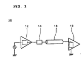
- FIG. 1 shows a digital circuit 10 which defines a simulation circuit.
- the digital circuit 10 provides noise analysis preferably for a circuit having digital ICs.
- the digital circuit 10 includes a transmitter IC 12, a filter 14 defining a noise suppression component, a transmission line 16, and a receiver IC 18.
- the transmission line 16 is a wiring substrate incorporating digital ICs.
- An input signal is input to the transmitter IC 12.
- the digital circuit 10 is shown, for example, on a computer display. Referring to Fig. 2, in step S1, information regarding the digital circuit 10 is input and is recorded in memory. Information regarding the conditions of the input signal, such as the clock frequency, duty ratio, rise time, and fall time, is input. Such input signal information can be entered using any suitable input device, such as a keyboard.
- the input information regarding the transmitter IC 12 includes the inductance, capacitance, and resistance of an equivalent LCR circuit in which the digital IC is formed of passive devices.
- the program includes, as data, inductances, capacitances, and resistances of a plurality of digital ICs. Once a digital IC used as the transmitter IC 12 is selected, the inductance, capacitance, and resistance of the selected digital IC is entered. An input device, such as a mouse, can be used to select a digital IC from a list of ICs shown on the display.
- an IC category that is, either a CMOS type or a TTL type
- An input device such as a keyboard, can be used to enter the values, such as the inductance, capacitance, and resistance, of the LCR circuit.
- desired conditions are set to specify the filter for use.
- the type of filter like a chip ferrite bead filter for example, is first selected.
- a filter size is selected. In this manner, the filter type and size are selected so as to set all filters associated with the selected type and size as possible filters for use in the digital circuit 10.
- the characteristic impedance and propagation constant of the transmission line 16, and the length of the transmission line 16 are also entered.
- the characteristic impedance and the propagation constant are determined from the line length, line width, substrate thickness, substrate material, and other factors.
- a program for determining the characteristic impedance, the propagation constant, and other values, from such values is installed, thus facilitating entry of the characteristic impedance, the propagation constant, and other values.
- the characteristic impedance, the propagation constant, and other values are determined by a user, and are directly entered using an input device such as a keyboard. If other option that the transmission line is left out of consideration is prepared, the characteristic impedance and propagation constant of the transmission line 16 may be ignored for the noise analysis.
- the inductance, capacitance, and resistance of an equivalent LCR circuit in which the digital IC is formed of passive devices are also entered.
- these values can be entered by selecting an IC from a list of ICs stored as data in the program, or can be entered using an input device such as a keyboard.
- step S2 the input signal is expanded by Fourier expansion so as to be reduced to frequency components.
- a digital signal typically has a trapezoidal waveform.
- This signal is Fourier-expanded into harmonic components at integer multiples of the signal frequency, and is expressed as follows: where ⁇ n indicates the angular frequency, and
- step S3 the signal is calculated for each of a case where the filter is provided and a case where the filter is not provided.
- one of the selected filters is automatically selected, and the impedance of the selected filter is input.
- the impedances of all filters may be stored as data in the program.
- the impedance of the selected filter is input from this data and is recorded into memory.
- the mark " ⁇ " above a letter as is shown in Z ⁇ represents a complex number. Based on such information, the circuit constants of the digital circuit 10 without the filter 14 and the circuit constants of the digital circuit 10 with the filter 14 are calculated and recorded into a memory or the like.
- V ⁇ receiver Z in Z 0 Z 0 cosh( ⁇ l ) + Z in sinh(( ⁇ l ) V 0 Z out + Z + Z 1
- Z ⁇ 1 A Z in + B C Z in + D
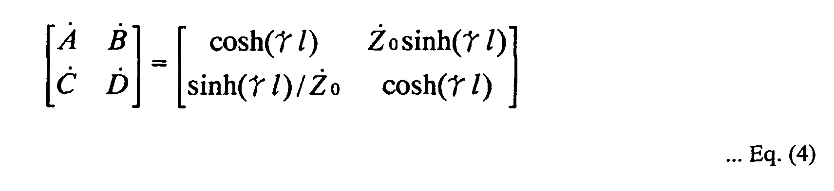
- a ⁇ , B ⁇ , C ⁇ , and D ⁇ are the elements of the F-matrix of the transmission line 16.
- the F-matrix is expressed as follows:
- Equation (2) if the impedance of the digital circuit 10 or the filter 14 has frequency response, the respective values at a high frequency are required.
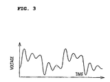
- the voltage V ⁇ receiver on the input side of the receiver IC 18 is determined by the above-described calculation. A voltage waveform for each of the fundamental and harmonic components of the input signal is obtained, and the sum is then subjected to an inverse Fourier transform to obtain a time-domain voltage waveform shown in Fig. 3. With respect to the magnitude
- step S3 the above-described analysis is performed for each of the cases where the filter 14 is used and not used.
- the results are compared to analyze the effects of the filter 14.
- the analysis for the case where the filter 14 is used and the analysis for the case where the filter 14 is not used are performed by using the circuit constants of the digital circuit 10 with the filter 14 and the circuit constants of the digital circuit 10 without the filter 14, respectively.
- the analysis is performed for all of the possible filters 14, and the filters 14 are ranked according to the results.
- step S4 the signal obtained in the case where the filter 14 is used and the signal obtained in the case where the filter 14 is not used are expressed in terms of the amplitude and phase for each of the fundamental and harmonic components for evaluation.
- the harmonic components In order to achieve noise suppression, the harmonic components must be reduced for the cases where the filter 14 is used and is not used. However, if the amplitude of low-order harmonic waves, such as up to fifth harmonic waves, greatly decreases, the signal waveform, which is a sum of harmonic waves, exhibits a reduction in amplitude or is degraded at rise/fall time. It is therefore desirable that the amplitude of such low-order harmonic waves does not substantially decrease.
- scores are assigned for each of the fundamental and harmonic components, such that a point P 1 is given the fundamental (first harmonic) amplitude, a point P 2 the second harmonic amplitude, a point P 3 the third harmonic amplitude, ..., a point P n the n-th harmonic amplitude.
- the difference between the signals at the input terminal of the receiver IC 18 in the cases where the filter 14 is used and not used is determined to obtain the amplitude difference for each of the fundamental and harmonic components. Then, the amplitude difference for each of the fundamental and harmonic components is scored. Basically, a high score is assigned in the noise-free state, i.e., the state where the harmonic components are reduced. However, as described above, the signal waveform is degraded when the low-order harmonic amplitude greatly decreases, and a high score should not be assigned where the fundamental and harmonic components are reduced, which causes degradation to the signal waveform.
- a scoring standard is determined empirically after the amount of noise reduction and the change in the signal waveform are measured for the cases where each of a plurality of filters is used and not used.
- the determined scoring standard is stored in advance as data in the program, and the amplitude is scored based on this data.
- a certain harmonic amplitude considerably increases when the filter 14 is not used, thus causing signal waveform distortion, such as ringing.
- the effects of the filter 14 may not be sufficiently evaluated by the above-described scoring method, and a different scoring standard is required.
- This scoring standard is also determined empirically. Which scoring standard is used is determined by, for example, determining the difference between the amplitude of the signal at the input terminal of the receiver IC 18 in the case where the filter 14 is not used and the amplitude of the input signal to determine whether or not the difference exceeds a predetermined threshold.
- the difference between these amplitudes is below the threshold, it is determined that ringing is not produced.
- the difference between the amplitudes of the signals at the input terminal of the receiver IC 18 in the case where the filter 14 is used and in the case where the filter 14 is not used is determined, and the scoring standard described above is used for each of the fundamental and harmonic components. If the difference between the signal amplitude at the input terminal of the receiver IC 18 in the case where the filter 14 is not used and the amplitude of the input signal is greater than the threshold, it is determined that ringing is produced.
- the difference between the amplitude of the signal at the input terminal of the receiver IC 18 in the case where the filter 14 is used and the amplitude of the input signal is determined, and a second, different scoring standard is used for each of the fundamental and harmonic components.
- the phase difference between the signals on the input side of the receiver IC 18 in the case where the filter 14 is used and in the case where the filter 14 is not used is also scored.
- the phase of low-order and odd-numbered-order harmonic waves affects the signal waveform.
- the high-order harmonic waves and the even-numbered-order harmonic waves having a small amplitude have less effect on the signal waveform, and thus, the effect of the phase of such harmonic waves on the signal waveform is negligible.
- the difference of the fundamental (first harmonic) phases between the cases where the filter 14 is used and not used is determined to predict a signal delay caused by the filter 14.
- the third and fifth harmonic phases cause signal waveform distortion due to the deviation from the fundamental phase.
- scores are assigned such that a point Q 1 is provided for the fundamental phase, a point Q 3 is provided for the third harmonic phase, and a point Q 5 is provided for the fifth harmonic phase.
- a scoring standard for phase evaluation is also determined empirically by measuring the signal waveform distortion in the cases where each of a plurality of filters is used and not used.
- a total score of the scores regarding the harmonic amplitudes and phases determined in consideration of the noise suppressing effects and the effect on the signal waveform is determined by the following equation: where a n and b n indicate weighting coefficients, which are dependent upon the expected degree of noise suppression, the effect on the signal waveform, and other factors. Each of the coefficients a n and b n is preferably set to a different value, for example, when focusing on noise suppression, when focusing on the signal waveform quality, and when balancing the noise suppression and the signal waveform quality. For example, when the filter 14 for use in the digital circuit 10 is specified, the focus on noise suppression, the signal waveform quality, or the balance therebetween is selected to determine the weighting coefficients used to calculate the total scores.
- step S6 whether or not the total scores are obtained for all possible filters is determined. If the total scores are not obtained for all possible filters, the operation in steps S3 through S5 is repeated until the total scores are obtained for all possible filters.
- the total scores are calculated using the initially entered values as the information about the components of the digital circuit 10 other than the filter 16, and using the information of each selected filter 16, which is automatically entered from the stored data.
- step S7 the filters are ranked from high score to low score. Since the input signal, which is subjected to Fourier expansion, is expressed in terms of a sum of a plurality of sine waves, the scores are determined by general linear computation using a personal computer without requiring a large-scale or middle-scale computer.
- step S8 the ranked filters are shown on the display in order from high score to low score.
- step S9 one of the displayed filters is selected, and the signal waveform in the case where the selected filter is used is simulated.
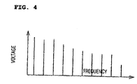
- step S10 the result is displayed as the signal waveform shown in Fig. 2 and the signal spectrum shown in Fig. 3. The simulation with respect to the filters enables the effects of the ranked filters to be compared, such that a suitable filter is selected.
- Such a filter selecting apparatus enables filters suitable for digital circuit 10 to be ranked and displayed once the circuit constants of the digital circuit 10 are set. This facilitates selection of a suitable filter, which prevents a person unfamiliar with noise countermeasures from selecting an unsuitable filter, so as to achieve quick filter selection.
- the weighting coefficients a n and b n can be changed to obtain a selection standard desirable to the person who selects the component, such as a selection method focusing on the noise suppressing effect or a selection method focusing on the signal waveform quality.
- Such a program for implementing the method of various preferred embodiments of the present invention preferably can be recorded in a recording medium, such as a CD-ROM (compact disc read-only memory).
- the program stored in the recording medium, such as a CD-ROM is then preferably installed in a personal computer, thereby achieving a filter selecting apparatus.
- the program may also be recorded in any other medium, such as a hard disk of a server computer, so as to allow users to download the program from a web site.
- a filter manufacturer distributes a program including data of manufactured filters to customers, thus enabling the customers to select a suitable filter.
- a user of a digital circuit is able to easily select a suitable filter for the digital circuit from the filters provided by the filter manufacturer who distributes the program. Accordingly, it is beneficial to filter manufacturers in view of sales promotion of filters that the program is distributed to customers via CD-ROM or that the customers be permitted to download the program from a web site.
Landscapes
- Engineering & Computer Science (AREA)
- Computer Hardware Design (AREA)
- Theoretical Computer Science (AREA)
- Physics & Mathematics (AREA)
- Health & Medical Sciences (AREA)
- Geometry (AREA)
- General Physics & Mathematics (AREA)
- General Engineering & Computer Science (AREA)
- Evolutionary Computation (AREA)
- Rehabilitation Therapy (AREA)
- Pain & Pain Management (AREA)
- Life Sciences & Earth Sciences (AREA)
- Physical Education & Sports Medicine (AREA)
- Veterinary Medicine (AREA)
- Animal Behavior & Ethology (AREA)
- Public Health (AREA)
- General Health & Medical Sciences (AREA)
- Epidemiology (AREA)
- Microelectronics & Electronic Packaging (AREA)
- Noise Elimination (AREA)
Abstract
Description


Claims (16)
- A noise suppression component selecting method for selecting a noise suppression component suitable for noise suppression in a digital circuit, the method comprising:a step of determining an amplitude and phase of a signal at a given position of the digital circuit when an input signal is input to the digital circuit;a step of determining an amplitude and phase of the signal at the given position when the input signal is input to the digital circuit in the case where the circuit includes each of a plurality of noise suppression components;a comparing step of comparing, for each order of fundamental and harmonic components, between the amplitude and phase of the signal at the given position determined in the case where the digital circuit includes each of the plurality of noise suppression components and the amplitude and phase of the signal at the given position determined in the case where the digital circuit does not include each of the plurality of noise suppression components;a scoring step of scoring, for each order of fundamental and harmonic components, the compared amplitude and phase obtained in the comparing step determined in the cases where the digital circuit includes each of the noise suppression components and does not include each of the noise suppression components; anda summing step of calculating a total score by summing the scored amplitude and phase by weighting for each order.
- A noise suppression component selecting method according to Claim 1, wherein the input signal is expanded into a series of sine waves by Fourier expansion before the signal is input to the digital circuit;in the scoring step, the signal at the given position is scored considering noise suppression and the signal waveform quality of the signal at the given position; andthe noise suppression component selection method further includes a ranking step of ranking the noise suppression components from a high score to a low score.
- A noise suppression component selection method according to Claim 2, wherein in the scoring step, different scoring standards are used depending upon the order of the fundamental and harmonic components of the signal at the given position so as to consider the noise suppression and the signal waveform quality.
- A noise suppression component selecting method according to Claim 2, wherein a standard for ranking the noise suppression components by weighting the scores is adjusted by focusing on at least one of the noise suppression in the signal at the given position and the signal waveform quality of the signal at the given position.
- A program for causing a computer to execute:a procedure A of recording a circuit constant of a digital circuit;a procedure B of expanding an input signal to the digital circuit into a series of sine waves by Fourier expansion;a procedure C of calculating a signal at a given position of the digital circuit using the circuit constant recorded in the procedure A when the input signal expanded into a series of sine waves in the procedure B is input;a procedure D of recording a circuit constant of the digital circuit in the case where the circuit includes one of a plurality of noise suppression components;a procedure E of calculating a signal at the given position of the digital circuit using the circuit constant recorded in the procedure D when the input signal expanded into a series of sine waves in the procedure B is input;a procedure F of determining a difference between the signal obtained in the procedure C and the signal obtained in the procedure E;a procedure G of scoring an amplitude and phase of the signal difference determined in the procedure F for each harmonic order;a procedure H of calculating a total score which is a sum of the scores obtained in the procedure G;a procedure I of implementing the procedures D through G for all of the plurality of noise suppression components to determine the total score in the case where each of the noise suppression components is used; anda procedure J of ranking the noise suppression components from a high score to a low score based on the total scores obtained in the procedure I.
- A program according to Claim 5, wherein the amplitude and phase are scored using different scoring standards depending upon each harmonic order.
- A program according to Claim 5, wherein the total score is calculated by weighting for each harmonic order.
- A program according to Claim 7, wherein the weighting by which the scores are determined is changed by focusing on at least one of noise suppression in the signal at the given position of the digital circuit and the signal waveform quality of the signal at the given position.
- A computer-readable recording medium having the program according to Claim 5 recorded thereon.
- A noise suppression component selecting apparatus comprising a computer in which the program according to Claim 5 is installed.
- A program for causing a computer to execute:a procedure K of recording a circuit constant of a digital circuit;a procedure L of expanding an input signal to the digital circuit into a series of sine waves by Fourier expansion;a procedure M of recording a circuit constant of the digital circuit in the case where the circuit includes one of a plurality of noise suppression components;a procedure N of calculating a signal at a given position of the digital circuit using the circuit constant recorded in the procedure M when the input signal expanded into a series of sine waves in the procedure L is input;a procedure O of determining a difference between the input signal expanded into a series of sine waves in the procedure L and the signal obtained in the procedure N;a procedure P of scoring an amplitude and phase of the signal difference determined in the procedure O for each harmonic order;a procedure Q of calculating a total score which is a sum of the scores obtained in the procedure P;a procedure R of implementing the procedures M through Q for all of the plurality of noise suppression components to determine the total score in the case where each of the noise suppression components is used; anda procedure S of ranking the noise suppression components from a high score to a low score based on the total scores obtained in the procedure R.
- A program according to Claim 11, wherein the amplitude and phase are scored using different scoring standards depending upon each harmonic order.
- A program according to Claim 11, wherein the total score is calculated by weighting for each harmonic order.
- A program according to Claim 13, wherein the weighting by which the scores are determined is changed by focusing on at least one of noise suppression in the signal at the given position of the digital circuit and the signal waveform quality of the signal at the given position.
- A computer-readable recording medium having the program according to Claim 11 recorded thereon.
- A noise suppression component selecting apparatus comprising a computer in which the program according to Claim 11 is installed.
Applications Claiming Priority (4)
| Application Number | Priority Date | Filing Date | Title |
|---|---|---|---|
| JP2003009369 | 2003-01-17 | ||
| JP2003009369 | 2003-01-17 | ||
| JP2003345901A JP4120555B2 (en) | 2003-01-17 | 2003-10-03 | Noise countermeasure component selection method and program |
| JP2003345901 | 2003-10-03 |
Publications (2)
| Publication Number | Publication Date |
|---|---|
| EP1443433A2 true EP1443433A2 (en) | 2004-08-04 |
| EP1443433A3 EP1443433A3 (en) | 2010-08-04 |
Family
ID=32658585
Family Applications (1)
| Application Number | Title | Priority Date | Filing Date |
|---|---|---|---|
| EP04000880A Withdrawn EP1443433A3 (en) | 2003-01-17 | 2004-01-16 | Noise suppression component selecting method and program |
Country Status (5)
| Country | Link |
|---|---|
| US (1) | US7032195B2 (en) |
| EP (1) | EP1443433A3 (en) |
| JP (1) | JP4120555B2 (en) |
| KR (1) | KR100570172B1 (en) |
| CN (1) | CN1304995C (en) |
Families Citing this family (6)
| Publication number | Priority date | Publication date | Assignee | Title |
|---|---|---|---|---|
| US6950997B2 (en) * | 2003-04-28 | 2005-09-27 | International Business Machines Corporation | Method and system for low noise integrated circuit design |
| US7088109B2 (en) * | 2004-09-30 | 2006-08-08 | Agilent Technologies, Inc. | Method and apparatus for measuring a digital device |
| RU2343630C1 (en) * | 2007-03-05 | 2009-01-10 | ОАО "Электроавтоматика" | Method of suppressing non-symmetrical conducted noise |
| JP5943593B2 (en) * | 2011-12-02 | 2016-07-05 | キヤノン株式会社 | Design support apparatus and information processing method thereof |
| US10706197B2 (en) * | 2018-05-24 | 2020-07-07 | Hitachi, Ltd. | Automated electromagnetic interference filter design |
| CN110057317B (en) * | 2018-11-16 | 2020-10-30 | 中山大学 | A Projection Noise Removal Method Based on Singular Value Decomposition and Lookup Table Construction |
Family Cites Families (8)
| Publication number | Priority date | Publication date | Assignee | Title |
|---|---|---|---|---|
| CN2082421U (en) * | 1991-03-12 | 1991-08-07 | 王海 | Harmonic analysing instrument |
| US5504833A (en) * | 1991-08-22 | 1996-04-02 | George; E. Bryan | Speech approximation using successive sinusoidal overlap-add models and pitch-scale modifications |
| JPH08273278A (en) * | 1995-03-29 | 1996-10-18 | Matsushita Electric Ind Co Ltd | CD-ROM device and control method thereof |
| US6035257A (en) * | 1997-12-10 | 2000-03-07 | Pelton Company | Method and apparatus for reducing harmonic distortion |
| CN1231451A (en) * | 1998-04-06 | 1999-10-13 | 赵春明 | Method and apparatus for calibrating error having functional relation with frequency in ac processing |
| JP2001265848A (en) * | 2000-03-22 | 2001-09-28 | Murata Mfg Co Ltd | Digital circuit noise analysis method, noise analysis device, and recording medium |
| US7133568B2 (en) * | 2000-08-04 | 2006-11-07 | Nikitin Alexei V | Method and apparatus for analysis of variables |
| US6950997B2 (en) * | 2003-04-28 | 2005-09-27 | International Business Machines Corporation | Method and system for low noise integrated circuit design |
-
2003
- 2003-10-03 JP JP2003345901A patent/JP4120555B2/en not_active Expired - Lifetime
-
2004
- 2004-01-13 US US10/755,312 patent/US7032195B2/en not_active Expired - Lifetime
- 2004-01-16 CN CNB2004100073263A patent/CN1304995C/en not_active Expired - Lifetime
- 2004-01-16 EP EP04000880A patent/EP1443433A3/en not_active Withdrawn
- 2004-01-17 KR KR1020040003545A patent/KR100570172B1/en not_active Expired - Lifetime
Also Published As
| Publication number | Publication date |
|---|---|
| CN1304995C (en) | 2007-03-14 |
| EP1443433A3 (en) | 2010-08-04 |
| CN1517919A (en) | 2004-08-04 |
| KR100570172B1 (en) | 2006-04-12 |
| US7032195B2 (en) | 2006-04-18 |
| US20040143804A1 (en) | 2004-07-22 |
| KR20040066729A (en) | 2004-07-27 |
| JP2004240947A (en) | 2004-08-26 |
| JP4120555B2 (en) | 2008-07-16 |
Similar Documents
| Publication | Publication Date | Title |
|---|---|---|
| US7907738B2 (en) | Speaker equalization tool | |
| US6088523A (en) | Method and apparatus for simulating an electrical circuit design using approximate circuit element tapers | |
| JP5911492B2 (en) | Information retrieval system, method, and program | |
| JP2000174087A (en) | Semiconductor device noise analysis device and semiconductor device | |
| JP4507421B2 (en) | Passive element equivalent circuit model derivation method, simulator, and storage medium | |
| EP1443433A2 (en) | Noise suppression component selecting method and program | |
| US20030083856A1 (en) | Model analyzing method and apparatus, and storage medium | |
| CN113742930A (en) | Method and device for evaluating noise annoyance degree of power transmission and transformation equipment and storage medium | |
| US20020032555A1 (en) | Method of and apparatus for signal-waveform simulation, and computer product | |
| JP5067736B2 (en) | Equivalent circuit parameter generator | |
| US20040205680A1 (en) | Method and apparatus for characterizing the propagation of noise through a cell in an integrated circuit | |
| US20120269230A1 (en) | Method for calculating causal impulse response from a band-limited spectrum | |
| US20010048298A1 (en) | Method and apparatus for analyzing noise in a digital circuit, and storage medium storing an analysis program | |
| US7337087B2 (en) | Circuit analyzing apparatus, circuit analyzing method and circuit analyzing program | |
| JP4216088B2 (en) | Apparatus and method for calculating the impedance of a circuit board | |
| JP6252494B2 (en) | Design support apparatus, design support method, and program | |
| JP2024111481A (en) | Acoustic characteristic calculation device, acoustic characteristic calculation method, program, and acoustic characteristic calculation system | |
| US7263676B2 (en) | Method and apparatus for detecting and analyzing the propagation of noise through an integrated circuit | |
| JP4202222B2 (en) | Transmission line analysis method and apparatus | |
| JP4185098B2 (en) | Transmission signal analysis program, method and apparatus | |
| US20230244843A1 (en) | Method for simulating system and associated electronic device | |
| US20040249603A1 (en) | Transient response analysis program of capacitor, recording medium, method of analysis, and simulator | |
| JP4760610B2 (en) | Noise analysis method, noise analysis device, and noise analysis control program | |
| JP2013110147A (en) | Noise analysis model and noise analysis method | |
| US20160110487A1 (en) | Identifying noise couplings in integrated circuit |
Legal Events
| Date | Code | Title | Description |
|---|---|---|---|
| PUAI | Public reference made under article 153(3) epc to a published international application that has entered the european phase |
Free format text: ORIGINAL CODE: 0009012 |
|
| 17P | Request for examination filed |
Effective date: 20040116 |
|
| AK | Designated contracting states |
Kind code of ref document: A2 Designated state(s): AT BE BG CH CY CZ DE DK EE ES FI FR GB GR HU IE IT LI LU MC NL PT RO SE SI SK TR |
|
| AX | Request for extension of the european patent |
Extension state: AL LT LV MK |
|
| RAP1 | Party data changed (applicant data changed or rights of an application transferred) |
Owner name: MURATA MANUFACTURING CO., LTD. |
|
| PUAL | Search report despatched |
Free format text: ORIGINAL CODE: 0009013 |
|
| AK | Designated contracting states |
Kind code of ref document: A3 Designated state(s): AT BE BG CH CY CZ DE DK EE ES FI FR GB GR HU IE IT LI LU MC NL PT RO SE SI SK TR |
|
| AX | Request for extension of the european patent |
Extension state: AL LT LV MK |
|
| AKX | Designation fees paid |
Designated state(s): AT BE BG CH CY CZ DE DK EE ES FI FR GB GR HU IE IT LI LU MC NL PT RO SE SI SK TR |
|
| STAA | Information on the status of an ep patent application or granted ep patent |
Free format text: STATUS: THE APPLICATION IS DEEMED TO BE WITHDRAWN |
|
| 18D | Application deemed to be withdrawn |
Effective date: 20140801 |