EP1443429A1 - Method for linking work attribute information, its system and model structure of sheet metal component - Google Patents
Method for linking work attribute information, its system and model structure of sheet metal component Download PDFInfo
- Publication number
- EP1443429A1 EP1443429A1 EP02767915A EP02767915A EP1443429A1 EP 1443429 A1 EP1443429 A1 EP 1443429A1 EP 02767915 A EP02767915 A EP 02767915A EP 02767915 A EP02767915 A EP 02767915A EP 1443429 A1 EP1443429 A1 EP 1443429A1
- Authority
- EP
- European Patent Office
- Prior art keywords
- attribute information
- sheet metal
- working attribute
- working
- model
- Prior art date
- Legal status (The legal status is an assumption and is not a legal conclusion. Google has not performed a legal analysis and makes no representation as to the accuracy of the status listed.)
- Withdrawn
Links
Images







Classifications
-
- G—PHYSICS
- G06—COMPUTING OR CALCULATING; COUNTING
- G06T—IMAGE DATA PROCESSING OR GENERATION, IN GENERAL
- G06T19/00—Manipulating three-dimensional [3D] models or images for computer graphics
-
- G—PHYSICS
- G06—COMPUTING OR CALCULATING; COUNTING
- G06F—ELECTRIC DIGITAL DATA PROCESSING
- G06F30/00—Computer-aided design [CAD]
- G06F30/10—Geometric CAD
- G06F30/17—Mechanical parametric or variational design
-
- G—PHYSICS
- G06—COMPUTING OR CALCULATING; COUNTING
- G06F—ELECTRIC DIGITAL DATA PROCESSING
- G06F2113/00—Details relating to the application field
- G06F2113/24—Sheet material
-
- G—PHYSICS
- G06—COMPUTING OR CALCULATING; COUNTING
- G06T—IMAGE DATA PROCESSING OR GENERATION, IN GENERAL
- G06T2219/00—Indexing scheme for manipulating 3D models or images for computer graphics
- G06T2219/004—Annotating, labelling
Definitions
- the present invention relates to a working attribute information linking method, a system for the same, and a model structure of a sheet metal component, and particularly, to a working attribute information linking method and a system for the same to provide a new outsourcing contractor with working know-how accumulated through, for example, outsourcing services by linking working attribute information to a bend model, i.e., a three-dimensional solid model of a sheet metal product and a model structure of a sheet metal component used to edit the sheet metal component by computer.
- a bend model i.e., a three-dimensional solid model of a sheet metal product and a model structure of a sheet metal component used to edit the sheet metal component by computer.
- a bend model or a three-dimensional solid model of, for example, a sheet metal product is provided with working attribute information which is electronic data representing only part of written information on design drawings of the sheet metal product prepared at a purchaser.
- the working attribute information to be provided is standard attribute data such as data for dividing a model into component models and bend line data for unfolding bend positions of a bend model.
- Working attribute information for preparing NC data for NC-machining a sheet metal product is added to, for example, an unfolded form of a component model.
- an outsourcing center partly takes over the manufacturing of a sheet metal product for an order receiver according to a request from the order receiver.
- the outsourcing center also takes over computer operation (for example, CAD/CAM operation) for the order receiver.
- Working know-how for example, tips for special working obtained from the work relegated to the outsourcing center is only verbally informed to persons concerned.
- design drawings transmitted from a purchaser to an order receiver describe every piece of information necessary for manufacturing a sheet metal product, and therefore, all of such information pieces are required to be added as working attnbute information to a bend model.
- a bend model interface for example, an interface program for reading bend model data for CAD/CAM software
- existing application software for example, CAD/CAM software to handle bend models
- Another problem is that only adding partial information to a bend model hinders digitization of working know-how and prevents proper transfer of information.
- CAD computer aided design
- Designing sheet metal components involves the editing of butting parts of a sheet metal model. More precisely, it is necessary to edit a connection where nonparallel two sheet-metal faces butt against each other (butting) and a connection where parallel two sheet-metal faces lap over each other (lapping).
- FIGs. 1A to 1E are views explaining concrete examples of editing a butting part on a conventional sheet metal model.
- a sheet metal component having an unfolded view of FIG. 1A and a solid view of FIG. 1C is considered.
- the sheet metal component has an apex "a" as shown in the solid view, and around the apex, involves a both-side-contracted butting part as shown in an enlarged partial view of FIG. 1B.
- a dotted line represents a bend line, and the same is applicable to the following description.
- a sheet thickness or a welding method may be changed to raise a necessity of changing the butting part.
- FIG. 1E In an enlarged partial view of FIG. 1E, the butting part is changed to one-side-contracted butting.
- CAD must be employed to again edit the shape of sheet metal as shown in an unfolded view of FIG. 1D. This is because CAD stores only a final shape of sheet metal.
- FIGs. 1D and 1E indicate directions in which the sheet metal is extended from the one-side-contracted state serving as a reference to the both-side-contracted state.
- FIGs. 2A to 2F are views explaining concrete examples of editing to be carried out when a sheet thickness is changed on a conventional sheet metal model.
- FIG. 2A corresponds to FIG. 1D and FIG. 2B to FIG. 1E.
- the sheet metal model must be edited again. Namely, the shape of the sheet metal must be changed as shown in an unfolded view of FIG. 2E to avoid the interference. This realizes a one-side-contracted butting part containing the sheet thickness change as shown in an enlarged partial view of FIG. 2F.
- the conventional sheet metal model needs, if a sheet thickness is changed after the completion of the sheet metal model, a repetition of the editing of the sheet metal model to control connection parts. This increases the labor of an operator who edits the model as well as a risk of erroneous changes during the editing.
- the present invention provides a working attribute information linking method for linking working attribute information to a bend model, i.e., a three-dimensional solid model of a sheet metal product.
- the method includes the steps of displaying the bend model on a display unit and selecting a working attribute information adding location to which the working attribute information is linked, inputting the working attribute information to be linked to the working attribute information adding location, preparing a linkage between the working attribute information and the working attribute information adding location in the bend model, and storing the bend model in a bend model memory and the working attribute information in a working attribute information memory while maintaining the linkage.
- the method includes the step of displaying the bend model, working attribute information, and working attribute information adding location related to one another on the display unit.
- the step of displaying the bend model, working attribute information, and working attribute information adding location related to one another on the display unit includes the step of highlighting the working attribute information adding location of the bend model when the working attribute information is clicked.
- the method includes the editing step of changing, correcting, or deleting the working attribute information.
- the working attribute information is text data representative of the contents of working know-how.
- the method includes the step of retrieving the working attribute information to be added to the working attribute information adding location from a working know-how database that stores working know-how.
- the present invention also provides a working attribute information linking system for linking working attribute information to a bend model, i.e., a three-dimensional solid model of a sheet metal product.
- the system includes means for displaying the bend model on a display unit and selecting a working attribute information adding location to which the working attribute information is linked, means for inputting the working attribute information to be linked to the working attribute information adding location, means for preparing a linkage between the working attribute information and the working attribute information adding location in the bend model, and means for storing the bend model in a bend model memory and the working attribute information in a working attribute information memory while maintaining the linkage.
- An object of the present invention is to provide also a model structure of a sheet metal component capable of reducing the labor of repetitively editing connections whenever a sheet thickness or a welding method is changed.
- the model structure of a sheet metai component according to the present invention is used for editing the sheet metal component with the use of a computer, that the model structure includes a sheet metal object having graphic element data to define graphic elements for sheet metal, face data to define faces each composed of graphic elements, and connection data to define each connection between faces, and that the sheet metal object includes a sheet metal editing object corresponding to a sheet metal editing process.
- the sheet metal editing object corresponds to an editing process of sheet butting or an editing process of sheet lapping.
- the sheet metal editing object corresponding to an editing process of sheet butting includes, as attributes, a butting kind of both-side contraction, one-side contraction, or both-side extension, a gap, and a gap type.
- the sheet metal editing object corresponding to an editing process of sheet lapping includes, as attributes, a lapping kind of one-side contraction, cutoff, oblique, or 45-degrees, a gap, and a gap type.
- the present invention stores an editing process of sheet connection such as butting and lapping as an object in a sheet metal model and automatically changes an unfolded view in response to a change in a working method or material.
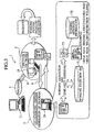
- FIG. 3 shows a schematic structure of the working attribute information linking system 1.
- the working attribute information linking system 1 includes a purchaser 3 that makes a request for manufacturing a sheet metal product, an order receiver 5 that receives the sheet metal manufacturing request from the purchaser 3 and manufactures the sheet metal product, and an outsourcing center 7 that carries out part of the work to be done by the order receiver 5.
- the purchaser 3, order receiver 5, and outsourcing center 7 communicate with one another through a communication system 9 such as the Internet.
- the purchaser 3 has a purchaser computer 11.
- the order receiver 5 has an order receiver computer 19.
- the outsourcing center 7 has an outsourcing center computer 39.
- the order receiver 5 requests the outsourcing center 7 to prepare, for example, an estimate and NC data for machine tools for machining the sheet metal product.
- the outsourcing center 7 prepares estimate data, NC data, and the like.
- a bend model i.e., a three-dimensional model of the sheet metal product must be prepared as three-dimensional CAD data.
- the estimate data and NC data are prepared.
- the bend model is linked to working attribute information (for example, a bend line of the bend model is linked to working attribute information which may be text data showing that the bend must carefully be made because shaping is to be conducted around the bend line).
- working know-how concerned is retrieved from a working know-how database 71 and is referred to.
- the working know-how database 71 is a storage area to store information accumulated from outsourcing services previously achieved by the outsourcing center 7.
- the working attribute information is stored in a memory separately from the bend model.
- the bend model is stored in a bend model memory 73
- the working attribute information is stored in a working attribute information memory 75.
- the bend model and working attribute information may have different file formats without correcting a bend model interface of an existing application.
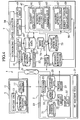
- the working attribute information linking system 1 includes, as mentioned above, the purchaser 3 that makes a request for manufacturing a sheet metal product, the order receiver 5 that receives the sheet metal manufacturing request from the purchaser 3 and manufactures the sheet metal product, and the outsourcing center 7 that carries out part of the work to be done by the order receiver 5.
- the purchaser 3, order receiver 5, and outsourcing center 7 communicate with one another through the communication system 9 such as the Internet.
- the purchaser 3 has the purchaser computer 11.
- the purchaser computer 11 includes a CAD/CAM unit 13 to design the product for the purchaser, an electronic drawing data memory 15 to store electronic drawing data designed by the CAD/CAM unit 13, and a transmitter 17 to read the electronic drawing data of the sheet metal product from the electronic drawing data memory and transmit the electronic drawing data to the order receiver 5, to request the order receiver for manufacturing the sheet metal product.
- the order receiver 5 has the order receiver computer 19 and an NC machine tool 21 to machine the sheet metal product.
- the order receiver computer 19 has a receiver 23, an electronic drawing data memory 25 to store electronic drawing data received through the receiver 23, and a transmitter 27 to transmit the electronic drawing data to the outsourcing center 7.
- the order receiver 5 also has a bend model memory 29 to store a bend model received through the receiver 23 and a working attribute information memory 31 to store received working attribute information.
- a link unit 33 maintains a linkage between the bend model and the working attribute information.
- a bend model is a three-dimensional solid model provided with electronic information representative of working attributes necessary for NC machine tools.
- the three-dimensional solid model is made by, for example, a three-dimensional CAD/CAM system.
- a display unit 35 reads the bend model from the bend model memory 29 and the working attribute information from the working attribute information memory 31 and displays them on a display unit 37.
- the bend model, working attribute information added locations (locations where working attribute information pieces are added) on the bend model, and the working attribute information are related to one another. As a result, an operator can easily refer to the working attribute information during actual working.
- working attribute information displayed on the display unit 37 It is prompted to select working attribute information displayed on the display unit 37.
- a working attribute information added location for example, an element linked to the selected working attribute information and contained in the bend model is, for example, highlighted.
- the operator who makes the sheet metal product can easily refer to the working know-how.
- a working attribute information added location is selected on the bend model, a linked piece of working attribute information is highlighted.
- the outsourcing center 7 has the outsourcing center computer 39.
- the outsourcing center computer 39 has a receiver 41, a CAD/CAM unit 43, a working attribute information managing unit 47 connected to the CAD/CAM unit 43 through a connection unit 45, and a display unit 49.
- Electronic drawing data received by the receiver 41 is stored in an electronic drawing data memory 51.
- a converter 53 reads the electronic drawing data from the electronic drawing data memory 51, converts the same into CAD/CAM data for the own CAD/CAM unit 43, and stores it in a CAD/CAM data memory 55.
- the CAD/CAM unit 43 reads the front, plan, and side views of the sheet metal product from the CAD/CAM data memory 55 and prepares a bend model (three-dimensional solid model).
- the bend model is divided into a plurality of component models, and for each of the component models, an unfolded view is prepared. Data related to the bend model, component models, and unfolded views are related to one another and are stored in the CAD/CAM data memory 55.
- the president, factory manager, bending engineers, and the like of the order receiver 5 and the CAD/CAM operators of the outsourcing center 7 hold a working editing meeting to prepare estimate data and NC data for the sheet metal product.
- the estimate data is transmitted from the order receiver 5 to the purchaser 3.
- the NC data is used when the order receiver 5 receives an official order, to quickly start working.
- the working attribute information managing unit 47 has a working attribute adding unit 57 and a working attribute editing unit 59.
- the working attribute adding unit 57 has an element specifying unit 61, a working attribute inputting unit 63, and a linkage forming unit 65.
- the element specifying unit 61 displays the bend model on the display unit 49 and prompts to click a working attribute information adding location (for example, an element such as a segment contained in the bend model) on the bend model with a mouse.
- a working attribute information adding location for example, an element such as a segment contained in the bend model
- the working attribute inputting unit 63 prompts to input, for example, working attribute information (for example, text data indicating that a hole is formed close to a bend line) with, for example, a keyboard.
- working attribute information for example, text data indicating that a hole is formed close to a bend line
- working know-how may be retrieved from the working know-how database 71 and be used to prepare the working attribute information.
- the linkage forming unit 65 forms a linkage between the working attribute information adding location (for example, an element such as a segment) specified on the bend model and the working attribute information.
- Data concerning the bend model is stored in the bend model memory 73.
- the working attribute information is stored in the working attribute information memory 75.
- a link unit 77 maintains linkage.
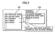
- FIG. 5 shows an example of the link unit.
- a linkage between element data 301 for example, a numeral 001 represents a circular hole, a numeral 002 a square hole, a numeral 003 forming, a numeral 004 a V-bend, a numeral 005 an R-bend, and the like
- a selected working attribute information adding location and working attribute information 303 for example, a numeral 001 represents a hole formed near a bend line, a numeral 002 a 2R-corner, and the like
- a working attribute information added location for example, an element such as a segment
- working attribute information for example, text data
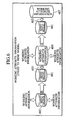
- FIG. 6 shows that a bend model (a file format of the bend model) is independent of working attribute information (a file format of the working attribute information) linked to the bend model.
- the bend model 401 is provided with working attribute information, and a link unit 403 links working attribute information 405 to the bend model. If working attribute information is further added to the bend model 401, there will be expanded working attribute information 407. However, the data contents of the bend model 401 are unchanged.
- CAD/CAM software reads and edits a bend model
- no working attribute information is read.
- an operator can refer to a bend model and working attribute information that is related to the bend model through the link unit.
- the working attribute editing unit 59 has a working attribute specifying unit 67 and a linked element specifying unit 69.
- the working attribute specifying unit 59 prompts to select working attribute information displayed on the display unit 49. Thereafter, the selected working attribute information is properly edited.
- the linked element specifying unit 69 selects a working attribute information added location (for example, an element such as a segment) on a bend model to which the working attribute information is linked. As a result, the working attribute information linked to the selected working attribute information added location is edited.
- a working attribute information added location for example, an element such as a segment
- a transmitter 79 transmits the bend model and working attribute information with a linkage being maintained therebetween by the link unit 77 to the order receiver 5.
- the order receiver computer 19 of the order receiver 5 can quickly execute application software using the bend model (for example, the bend model is displayed on the display unit to quickly start working).
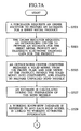
- step S501 the purchaser 3 requests the order receiver 5 to make an estimate for manufacturing a sheet metal product.
- step S503 the order receiver 5 requests the outsourcing center 7 to prepare an estimate for the metal sheet product.
- electronic drawing data and the like representative of design drawings of the sheet metal product are transmitted from the transmitter 27 to the outsourcing center 7.
- step S505 the outsourcing center computer 39 of the outsourcing center 7 prepares a solid model from the front, plan, and side views of the sheet metal product.
- the bend model of the sheet metal product is divided into component models (to perform proper processes). Thereafter, the component models are developed into unfolded views.
- the bend model, component models, unfolded views, and the like are related to one another.
- step S507 estimate data, NC data, and the like are prepared during the preparation of the bend model.
- step S509 the contents of the working know-how database are referred to, and working attribute information (for example, text data indicating that a shaping process is carried out in the vicinity of a bend line) is linked to a working attribute information adding location of the bend model.
- working attribute information for example, text data indicating that a shaping process is carried out in the vicinity of a bend line
- FIG. 8 shows a method of adding working attribute information to a working attribute information adding location of a bend model.
- the display 49 displays a screen 701.
- the screen shows a bend model 703.
- a working attribute information adding location 705 for example, an element such as a segment
- working attribute information for example, working know-how
- step S511 the transmitter 79 transmits the estimate data, NC data, bend model linked to working attribute information, and the like to the order receiver 5.
- step S513 the transmitter 27 of the order receiver 5 transmits an estimate and the like related to the manufacturing of the sheet metal product to the purchaser 3. Then, an official order for manufacturing the sheet metal product will be issued.
- step S515 the order receiver 5 uses the bend model, NC data for NC machine tools for machining the sheet metal product, and the like to manufacture the sheet metal product.
- the bend model is displayed on the display unit 37, and an operator performs actual work with reference to the working attribute information.
- FIG. 9 shows a method of letting an operator refer to working attribute information.
- the display unit 37 displays a screen 801.
- the screen 801 shows a bend model 803 and a working attribute information displaying window 805.
- the working attribute information displaying window 805 displays complete working attribute information linked to the bend model.
- working attribute information 807 is selected. Then, a working attribute information added location (for example, an element such as a segment) 809 of the bend model 803 linked to the working attribute information 807 is highlighted. Accordingly, the operator can easily refer to the working know-how.
- step S517 the order receiver 5, purchaser 3, and the like conduct, if needed, examinations such as VE and VA for manufacturing the product.
- step S519 data related to proposals from a result of the examination conducted in step S517 is transmitted to the outsourcing center computer 39 and is stored in the working know-how database 71 provided for the outsourcing center computer 39. This can be utilized for the next outsourcing service.
- a bend model may be provided with a hole attribute (for example, a fixed hole, an irregular hole/open path, a shaped/protruding hole, a special hole, a macro hole, marking, tapping, a stud, a weld nut, caulking, a press hole, and the like).
- a hole attribute for example, a fixed hole, an irregular hole/open path, a shaped/protruding hole, a special hole, a macro hole, marking, tapping, a stud, a weld nut, caulking, a press hole, and the like).
- a bend model may be linked to a material attribute (for example, a material name, a sheet thickness, a material, a tensile strength, and the like).
- a material attribute for example, a material name, a sheet thickness, a material, a tensile strength, and the like.
- a bend model may be linked to a bend line attribute (for example, a V-bend, an R-bend, a hemming bend, a stepped bend, and the like).
- a bend line attribute for example, a V-bend, an R-bend, a hemming bend, a stepped bend, and the like.
- a bend model may be linked to a bend shape attribute (a length difference, a bend direction, and bumping related to a bend line; a cut-raise bend, a blind bend, a deep bend, a small bend, a large bend, a thin sheet bend, and a thick sheet bend related to a butting or bending shape; and a gradual bend, a closing bend, and a stepped bend related to a special bend shape).
- a bend shape attribute a length difference, a bend direction, and bumping related to a bend line
- a gradual bend, a closing bend, and a stepped bend related to a special bend shape a bend shape attribute
- the present invention is not limited to the above-mentioned embodiment. By properly modifying the embodiment, the present invention is achievable in other forms.
- the working attribute information linking system stores working attribute information linked to a bend model in a memory that is different from a memory to store the bend model.
- a bend model may be provided with working attribute information having a different file format without correcting existing application software. This provides an effect of eliminating a need of updating applications already supplied to venders and an effect of reducing the number of software maintaining man-hours.
- a bend model may be linked to many pieces of working attribute information such as working know-how (text data). Such information can be referred to by a manufacturer of sheet metal products when carrying out processes, to reduce work mistakes and man-hours.
- FIG. 10 is a block diagram showing a schematic structure of a computer aided design (hereinafter simply referred to as CAD) system.
- CAD computer aided design
- the CAD system 100 has a central processing unit 101 to centrally conduct data processing for the CAD system 100, an auxiliary storage unit 102 to auxiliary store data processed by the central processing unit 101, a CRT display unit 103 to display character data and graphic data supplied from the central processing unit 101, a keyboard unit 104 to input character information, and a mouse 105 to input positional information and the like.
- the central processing unit 101 is an operational unit having a CPU, ROM, RAM, and the like to centrally conduct data processing for the CAD system 100.
- the editing of a sheet metal model to be explained later is achieved by executing a given program in this central processing unit.
- the auxiliary storage unit 102 is, for example, a hard disk drive to store a large amount of data.
- the auxiliary storage unit 102 stores a sheet metal model 102a having sheet metal editing objects. The details of the sheet metal model 102a will be explained later.
- the CRT display unit 103 includes a CRT to display pixel data based on a bitmap method. It displays character data and graphic data supplied from the central processing unit 102.
- the CRT display unit 103 displays, for example, unfolded and solid views of sheet metal components.
- the keyboard unit 104 has a plurality of keys to input character data.
- the keyboard unit 104 is used to input, for example, a gap at a butting part on a sheet metal component displayed on the CRT display unit 103.
- the mouse 105 is slid on a flat face such as a desk to input positional data, which is entered when a button is pushed down.
- the mouse 105 is used when inputting, for example, the shape of a sheet metal component on the CRT display unit 103.
- the CAD system 100 having the central processing unit 101, auxiliary storage unit 102, CRT display unit 103, keyboard unit 104, and mouse 105 may be realized with the use of, for example, a personal computer.
- the sheet metal model has an internal structure generally including graphic element data such as segments, arcs, circumferences, and the like to express component shapes, face data composed of the graphic elements, and connection data (bend lines) to define connections between the faces.
- graphic element data such as segments, arcs, circumferences, and the like to express component shapes
- face data composed of the graphic elements
- connection data (bend lines) to define connections between the faces.
- the sheet metal model according to the embodiment contains sheet metal editing objects representing sheet metal working for "butting” and “lapping” locations.
- Each sheet metal editing object enables the automatic handling of a change in the shape (unfolded shape) of a sheet metal component due to a change in a processing method such as welding, a change in sheet thickness, a change in material, and the like.
- the sheet metal model includes, as sheet metal editing objects, a butting object concerning the editing of connection (butting process) at a location where nonparallel two faces butt against each other in the sheet metal model and a connection object concerning the editing of connection (lapping process) at a location where parallel two faces butt against each other in a space of the sheet metal model.
- the "parallel” is not limited to strict parallel and includes a case in which two faces are slightly off-parallel from each other or overlap each other in a sheet thickness direction.
- this embodiment stores the editing work of a connection part of sheet metal as a sheet metal editing object in a sheet metal model. If a sheet thickness or a welding method is changed, parameters stored as attributes in the sheet metal editing object are used to automatically prepare a changed unfolded shape.
- this embodiment can eliminate manual work of changing an unfolded shape in the CAD system, to thereby reduce the labor of a designer.
- the embodiment can reduce erroneous changes to be made during the editing work.
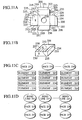
- FIGs. 11A to 11D are views explaining a concrete example of a sheet metal model.
- a sheet metal component edited based on this sheet metal model is shown in an unfolded view of FIG. 11A and a solid view of FIG. 11B.
- the sheet metal component consists of eight faces 231 to 238 connected together with seven bend lines 221 to 227.
- the sheet metal model representative of the sheet metal component consists of face data shown in FIG. 11C and bend line data shown in FIG. 11D.
- the face data of the faces 231 to 238 is defined with segments of graphic elements expressing shapes.
- the face 231 is defined with four segments, i.e., graphic elements 201, 202, 225, and 219.
- the other faces are defined in similar ways.
- the bend line data defines connections of the faces 221 to 227.
- the bend line 221 is defined to connect the faces 233 and 235 to each other.
- the other bend lines are similarly defined.
- FIGs. 12A and 12B are views explaining concrete examples of sheet metal editing objects.
- the sheet metal editing objects are stored in the sheet metal model shown in FIG. 11.
- FIG. 12 shows locations of "butting” and “lapping” of this sheet metal component.
- butting is a connection between two nonparallel faces. Butting 251 is present between faces 234 and 236, butting 252 between faces 233 and 236, and butting 253 between faces 236 and 237.
- the “lapping” is a connection between two parallel faces.
- Lapping 261 is present between faces 231 and 234 and lapping 262 between faces 231 and 238.
- Relationships at the "butting" and “lapping” connections are defined as butting objects and lapping objects as shown in the sheet metal editing objects of FIG. 12B.
- the butting object 251 is defined with the face 234, graphic element 207, face 236, and graphic element 210.
- the lapping object 261 is defined with the face 231, graphic element 202, face 234, and graphic element 205.
- FIGs. 13A to 13D are views explaining a concrete example of a butting object.
- the butting object corresponds to a "butting" editing process that determines a connection state of two nonparallel faces that butt against each other or cross each other, according to specified attribute parameters.
- One butting object is assigned to two faces and graphic elements (segments) of the faces existing at the butting location.
- a butting object is assigned to a graphic element 208 of a face 233 and a graphic element 209 of a face 236.
- This butting object is defined for a sheet metal model as shown in FIG. 13B.
- the butting object consists of the face 233, graphic element 208, face 236, and graphic element 209.
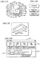
- FIG. 13C shows a solid view of a sheet metal component displayed on the CRT display unit 103 of the CAD system 100 shown in FIG. 10.
- the above-mentioned butting is present between the graphic element 208 of the face 233 and the graphic element 209 of the face 236.
- FIG. 13D shows a graphical user interface (GUI) for a butting process displayed on the CRT display unit 103.
- GUI graphical user interface
- the butting GUI 271 includes a butting kind setting zone 272 to set a butting kind, a gap setting zone 273 to set a gap at the butting, and a butting gap type setting zone 274 to set a butting gap type.
- the butting GUI 271 enables the setting of attributes with parameters concerning a butting object.
- the attributes set with parameters are stored in the butting object shown in FIG. 13B.
- the butting kind setting zone 272 it is possible to select a butting kind from among both-side contraction, one-side contraction 1, one-side contraction 2, and both-side extension.
- the one-side contraction 1 and one-side contraction 2 differ from each other in the face that is retracted.
- the butting gap setting zone 273 sets a butting gap for each of first and second sheet metal directions.
- the gap is identical in each direction for the both-side contraction or both-side extension, and different gaps are set for the one-side contraction.
- the butting gap type setting zone 274 allows to select a gap type from a percentage and a real value.
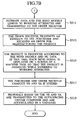
- the butting GUI 271 is edited with the keyboard unit 104 or the mouse 105 of the CAD system 100. The same is applicable to a lapping GUI to be explained later.
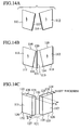
- FIGs. 14A to 14C are views explaining processes for a butting object.
- the processes for a butting object are carried out according to attribute values.
- the processes automatically regenerate a connection between faces of sheet metal if there is a change in a sheet thickness, welding method, and the like.
- FIG. 14A shows an initial state.
- a butting instruction specifies a butting location, e.g., a segment 113 of a face 111 and a segment 114 of a face 112. Such an instruction is made in the CAD system based on a change in a sheet thickness or welding method, or an automatic shaping request.
- FIG. 14B shows a calculation of a nodal line to obtain a nodal line 115 for the faces 111 and 112. Also obtained are an intersection 120 between the nodal line 115 and segments 116 and 118 adjacent to the butting segments 113 and 114 and an intersection 121 between the nodal line 115 and segments 117 and 119.
- FIG. 14C shows a calculation of a butting shape. Namely, a point 123 on a segment 130 between the intersection 120 and a point 122, a point 125 on a segment 131 between the intersection 120 and a point 124, a point 127 on a segment 132 between the intersection 121 and a point 126, and a point 129 on a segment 133 between the intersection 121 and a point 128 are calculated to satisfy sheet thickness and gap parameters A and B.
- FIGs. 15A to 15D are views explaining a concrete example of a lapping object.
- the lapping object corresponds to an editing process to determine a connection state between parallel two faces of sheet metal according to given attribute parameters.
- One lapping object is assigned for two faces and graphic elements (segments) of the two faces that are in contact with each other at the lapping location.
- a lapping object is assigned to a graphic element 2 of a face 231 and a graphic element 205 of a face 234.
- the lapping object is defined as shown in FIG. 15B. This lapping object consists of the face 231, graphic element 202, face 234, and graphic element 205.
- FIG. 15C is a solid view showing a sheet metal component of this example displayed on the CRT display unit 103 of the CAD system 100 shown in FIG. 10.
- the lapping is present between the graphic element 202 of the face 231 and the graphic element 205 of the face 234.
- FIG. 15D shows a lapping editing GUI displayed on the CRT display unit 103.
- the lapping GUI 281 includes a lapping kind setting zone 282 to set a lapping kind, a lapping gap setting zone 283 to set a lapping gap, and a lapping gap type setting zone 284 to set a lapping gap type.
- the lapping GUI 281 can set parameters representative of attributes of the lapping object.
- the set attribute parameters are stored in the lapping object shown in FIG. 15B.
- the one-side contraction 1 and one-side contraction 2 involve different retraction faces.
- the lapping gap type setting zone 284 one can select a gap type from a sheet thickness percentage and a real value.
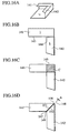
- FIGs. 16A to 16D are views explaining processes for a lapping object.
- the processes for a lapping object are carried out according to attribute values. These processes can automatically generate a connection between sheet metal faces when a change is made in a sheet thickness or in a welding method.
- a sheet metal component involves lapping to be processed between faces 141 and 142.
- dotted lines indicate bend lines.
- FIGs. 16A and 16B show an initial state.
- a segment 143 of the face 141 and a segment 144 of the face 142 are specified at the lapping location.
- the faces 141 and 142 have each a trapezoidal shape, and one of the top and bottom sides of each trapezoidal shape serves as a bend line.
- the "lapping" instruction is based on a lapping object.
- FIG. 16C shows a calculation of extensions of the two faces and an interference between them. Namely, it is tested whether or not the two faces 141 and 142 cross each other on the extensions in bend line directions. If they cross each other, one face is extended to a boundary of the opposite face (segment 145 in the FIG), to prepare a crossing shape.
- FIG. 16D shows a calculation of a lapping shape. To satisfy a lapping pattern "45-degrees" and a gap A, a segment 151 between points 146 and 147 and a segment 152 between points 148 and 149 are determined to regenerate faces 141' and 142'.
- FIGs. 17A and 17B are views explaining an automatic changing process for a sheet metal model having sheet metal editing objects.
- FIGs. visually show the sheet metal model 102a having sheet metal editing objects stored in the auxiliary storage unit 102 of the CAD system.
- the requests are handled by automatically changing the shape of a connection of the sheet metal component and preparing a changed sheet metal model shown in FIG. 17B.
- the automatic editing of the unfolded view is carried out according to a predetermined method such as the butting process of FIGs. 14A to 14C or the lapping process of FIGs. 16A to 16D.
- this embodiment can automatically process a connection such as a butting or lapping connection between sheet metal faces according to sheet metal editing objects.
- the present invention stores sheet metal editing processes such as butting and lapping processes as objects in a sheet metal model and automates changing an unfolded shape in response to a change in working such as welding, a change in sheet thickness, or a change in material.
Landscapes
- Physics & Mathematics (AREA)
- Engineering & Computer Science (AREA)
- Geometry (AREA)
- Theoretical Computer Science (AREA)
- General Physics & Mathematics (AREA)
- General Engineering & Computer Science (AREA)
- Computer Hardware Design (AREA)
- Software Systems (AREA)
- Computer Graphics (AREA)
- Computational Mathematics (AREA)
- Mathematical Analysis (AREA)
- Mathematical Optimization (AREA)
- Pure & Applied Mathematics (AREA)
- Evolutionary Computation (AREA)
- Bending Of Plates, Rods, And Pipes (AREA)
Abstract
Description
Claims (15)
- A working attribute information linking method for linking working attribute information to a bend model that is a three-dimensional solid model of a sheet metal product, comprising the steps of:displaying the bend model on a display unit and selecting a working attribute information adding location to which the working attribute information is linked;inputting the working attribute information to be linked to the working attribute information adding location;preparing a linkage between the working attribute information and the working attribute information adding location in the bend model; andstoring the bend model in a bend model memory and the working attribute information in a working attribute information memory while maintaining the linkage.
- The working attribute information linking method as set forth in claim 1, comprising the step of:displaying the bend model, working attribute information, and working attribute information adding location related to one another on the display unit.
- The working attribute information linking method as set forth in claim 2, wherein the step of displaying the bend model, working attribute information, and working attribute information adding location related to one another on the display unit includes the step of highlighting the working attribute information adding location of the bend model when the working attribute information is clicked.
- The working attribute information linking method as set forth in claim 1, 2, or 3, comprising the step of:editing that includes changing, correcting, or deleting the working attribute information.
- The working attribute information linking method as set forth in claim 1, 2, 3, or 4, wherein the working attribute information is text data representative of the contents of working know-how.
- The working attribute information linking method as set forth in claim 5, comprising the step of:retrieving the working attribute information to be added to the working attribute information adding location from a working know-how database that stores working know-how.
- A working attribute information linking system for linking working attribute information to a bend model that is a three-dimensional solid model of a sheet metal product, comprising:means for displaying the bend model on a display unit and selecting a working attribute information adding location to which the working attribute information is linked;means for inputting the working attribute information to be linked to the working attribute information adding location;means for preparing a linkage between the working attribute information and the working attribute information adding location in the bend model; andmeans for storing the bend model in a bend model memory and the working attribute information in a working attribute information memory while maintaining the linkage.
- A model structure of a sheet metal component used for editing the sheet metal component with the use of a computer, comprising:a sheet metal object having graphic element data for defining graphic elements of sheet metal, face data for defining faces each composed of graphic elements, and connection data for defining each connection between faces, and whereinthe sheet metal object includes a sheet metal editing object corresponding to a sheet metal editing process. ,
- The model structure of a sheet metal component as set forth in claim 8, wherein the sheet metal editing object corresponds to an editing process of sheet butting or an editing process of sheet lapping.
- The model structure of a sheet metal component as set forth in claim 9, wherein the sheet metal editing object corresponding to an editing process of sheet butting includes, as attributes, a butting kind of both-side contraction, one-side contraction, or both-side extension, a gap, and a gap type.
- The model structure of a sheet metal component as set forth in claim 9, wherein the sheet metal editing object corresponding to an editing process of sheet lapping includes, as attributes, a lapping kind of one-side contraction, cutoff, oblique, or 45-degrees, a gap, and a gap type.
- A model structure of a sheet metal component used for editing the sheet metal component with the use of a computer, comprising:a sheet metal object having graphic element data for defining graphic elements of sheet metal, face data for defining faces each composed of graphic elements, and connection data for defining each connection between faces, and whereinthe sheet metal object includes a sheet metal editing object corresponding to a sheet metal editing process.
- The model structure of a sheet metal component as set forth in claim 12, wherein the sheet metal editing object corresponds to an editing process of sheet butting or an editing process of sheet lapping.
- The model structure of a sheet metal component as set forth in claim 13, wherein the sheet metal editing object corresponding to an editing process of sheet butting includes, as attributes, a butting kind of both-side contraction, one-side contraction, or both-side extension, a gap, and a gap type.
- The model structure of a sheet metal component as set forth in claim 13, wherein the sheet metal editing object corresponding to an editing process of sheet lapping includes, as attributes, a lapping kind of one-side contraction, cutoff, oblique, or 45-degrees, a gap, and a gap type.
Applications Claiming Priority (5)
| Application Number | Priority Date | Filing Date | Title |
|---|---|---|---|
| JP2001275505A JP3643064B2 (en) | 2001-09-11 | 2001-09-11 | CAD equipment |
| JP2001275505 | 2001-09-11 | ||
| JP2001278075 | 2001-09-13 | ||
| JP2001278075A JP3741983B2 (en) | 2001-09-13 | 2001-09-13 | Machining attribute information link system |
| PCT/JP2002/009106 WO2003030035A1 (en) | 2001-09-11 | 2002-09-06 | Method for linking work attribute information, its system and model structure of sheet metal component |
Publications (2)
| Publication Number | Publication Date |
|---|---|
| EP1443429A1 true EP1443429A1 (en) | 2004-08-04 |
| EP1443429A4 EP1443429A4 (en) | 2010-12-01 |
Family
ID=26622018
Family Applications (1)
| Application Number | Title | Priority Date | Filing Date |
|---|---|---|---|
| EP02767915A Withdrawn EP1443429A4 (en) | 2001-09-11 | 2002-09-06 | Method for linking work attribute information, its system and model structure of sheet metal component |
Country Status (4)
| Country | Link |
|---|---|
| US (1) | US8725282B2 (en) |
| EP (1) | EP1443429A4 (en) |
| TW (1) | TWI232385B (en) |
| WO (1) | WO2003030035A1 (en) |
Cited By (2)
| Publication number | Priority date | Publication date | Assignee | Title |
|---|---|---|---|---|
| GB2569770A (en) * | 2017-09-05 | 2019-07-03 | Nissan Motor Mfg Uk Ltd | Method of blank design for a spin forming process |
| BE1028131B1 (en) * | 2020-03-09 | 2021-10-04 | Devos Plaatbewerkingen Nv | METHOD FOR SHEET METERING |
Families Citing this family (3)
| Publication number | Priority date | Publication date | Assignee | Title |
|---|---|---|---|---|
| CN108292130B (en) | 2015-11-19 | 2020-09-22 | 村田机械株式会社 | Information processing device, processing system, data structure, and data processing method |
| JP6907006B2 (en) * | 2017-04-10 | 2021-07-21 | 株式会社日立製作所 | Work consignment support system and its method |
| WO2022219777A1 (en) * | 2021-04-15 | 2022-10-20 | 株式会社小林製作所 | Server device and program |
Family Cites Families (13)
| Publication number | Priority date | Publication date | Assignee | Title |
|---|---|---|---|---|
| JPH06231215A (en) | 1993-02-03 | 1994-08-19 | Mitsubishi Electric Corp | Sheet metal cad/cam system |
| JPH07191721A (en) | 1993-12-27 | 1995-07-28 | Toshiba Corp | NC data generator for sheet metal processing |
| US6209420B1 (en) * | 1994-03-16 | 2001-04-03 | Baker Hughes Incorporated | Method of manufacturing bits, bit components and other articles of manufacture |
| US5526478A (en) | 1994-06-30 | 1996-06-11 | Silicon Graphics, Inc. | Three dimensional model with three dimensional pointers and multimedia functions linked to the pointers |
| US5886897A (en) * | 1996-05-06 | 1999-03-23 | Amada Soft America Inc. | Apparatus and method for managing and distributing design and manufacturing information throughout a sheet metal production facility |
| US5966135A (en) * | 1996-10-30 | 1999-10-12 | Autodesk, Inc. | Vector-based geographic data |
| GB2325996B (en) * | 1997-06-04 | 2002-06-05 | Lsi Logic Corp | Distributed computer aided design system and method |
| JP3612422B2 (en) | 1998-06-01 | 2005-01-19 | 株式会社アマダ | Computer-readable recording medium recording a sheet metal figure creation program |
| US6295513B1 (en) | 1999-03-16 | 2001-09-25 | Eagle Engineering Of America, Inc. | Network-based system for the manufacture of parts with a virtual collaborative environment for design, developement, and fabricator selection |
| JP3882389B2 (en) | 1999-05-11 | 2007-02-14 | 村田機械株式会社 | Sheet metal development drawing creation device |
| JP4402776B2 (en) | 1999-09-29 | 2010-01-20 | 株式会社アマダ | Sheet metal composite development drawing generation method using general-purpose two-dimensional CAD, general-purpose two-dimensional CAD system, and storage medium storing program of sheet-metal composite drawing generation method using general-purpose two-dimensional CAD |
| JP3224375B2 (en) * | 1999-11-16 | 2001-10-29 | 株式会社アマダ | Sheet metal model molding shape recognition method and apparatus, and storage medium storing program of sheet metal model molding shape recognition method |
| JP2001202111A (en) | 2000-01-20 | 2001-07-27 | Nec Corp | Device and method for inspecting production of sheet metal |
-
2002
- 2002-09-06 US US10/488,246 patent/US8725282B2/en not_active Expired - Fee Related
- 2002-09-06 EP EP02767915A patent/EP1443429A4/en not_active Withdrawn
- 2002-09-06 WO PCT/JP2002/009106 patent/WO2003030035A1/en not_active Ceased
- 2002-09-09 TW TW091120410A patent/TWI232385B/en not_active IP Right Cessation
Cited By (3)
| Publication number | Priority date | Publication date | Assignee | Title |
|---|---|---|---|---|
| GB2569770A (en) * | 2017-09-05 | 2019-07-03 | Nissan Motor Mfg Uk Ltd | Method of blank design for a spin forming process |
| GB2569770B (en) * | 2017-09-05 | 2020-02-26 | Nissan Motor Mfg Uk Ltd | Method of blank design for a spin forming process |
| BE1028131B1 (en) * | 2020-03-09 | 2021-10-04 | Devos Plaatbewerkingen Nv | METHOD FOR SHEET METERING |
Also Published As
| Publication number | Publication date |
|---|---|
| WO2003030035A1 (en) | 2003-04-10 |
| TWI232385B (en) | 2005-05-11 |
| EP1443429A4 (en) | 2010-12-01 |
| US8725282B2 (en) | 2014-05-13 |
| US20120109587A1 (en) | 2012-05-03 |
Similar Documents
| Publication | Publication Date | Title |
|---|---|---|
| EP1260890B1 (en) | Method for determining disposition of dies in a machine tool | |
| DE69726431T2 (en) | DEVICE AND METHOD FOR INTEGRATING AN INTELLIGENT MANUFACTURING SYSTEM WITH A SHEET PLANNING AND BENDING SYSTEM | |
| US7398129B2 (en) | Representation of sheet metal part models | |
| EP1057084B1 (en) | Apparatus and method for transferring and editing sheet metal part data | |
| DE69725346T2 (en) | DEVICE AND METHOD FOR PRODUCING A SHEET BENDING MODEL | |
| EP2126849B1 (en) | Implicit feature recognition for a solid modeling system | |
| JP5965859B2 (en) | Welding line information setting device, program, automatic teaching system, and welding line information setting method | |
| JP6022393B2 (en) | Welding line information setting device, program, automatic teaching system, and welding line information setting method | |
| JPH0673137B2 (en) | How to give an interface of parts list between a conceptual design tool and CAD / CAM environment | |
| Cheok et al. | Integrated feature-based modelling and process planning of bending operations in progressive die design | |
| US5293321A (en) | Curve extracting apparatus and NC programming system for forming NC program based on curves extracted by the apparatus | |
| US8725282B2 (en) | Method for linking work attribute information, its system and model structure of sheet metal component | |
| JP4774979B2 (en) | Sheet metal model creation system, sheet metal model creation method, and sheet metal model creation program | |
| JP6022394B2 (en) | Work route information setting device, program, and work route information setting method | |
| JP2624514B2 (en) | Method and apparatus for setting bending mold and bending order | |
| JP3741983B2 (en) | Machining attribute information link system | |
| JP3573958B2 (en) | Sheet metal integration support system and storage medium storing graphic data generation management program | |
| JPS61133478A (en) | Apparatus for assisting in creation and industrialization ofobject obtained by cutting and deforming sheet material | |
| JPH06187396A (en) | Network constitution design aid system | |
| JP4774978B2 (en) | Sheet metal model processing system, sheet metal model processing method, sheet metal model processing program, and data structure of object-oriented sheet metal model used by these | |
| JP3056397B2 (en) | Method for creating intermediate structure shape design data and method for creating tool path data | |
| JPH10161719A (en) | System constructing simulation device for industrial robot | |
| JP3937913B2 (en) | Information processing device | |
| JPH01309726A (en) | Bend data generation-management device for bending work | |
| JP4727835B2 (en) | Non-processable information teaching method and system |
Legal Events
| Date | Code | Title | Description |
|---|---|---|---|
| PUAI | Public reference made under article 153(3) epc to a published international application that has entered the european phase |
Free format text: ORIGINAL CODE: 0009012 |
|
| 17P | Request for examination filed |
Effective date: 20040413 |
|
| AK | Designated contracting states |
Kind code of ref document: A1 Designated state(s): BE CH DE FI FR GB IT LI NL |
|
| RIN1 | Information on inventor provided before grant (corrected) |
Inventor name: TAKAGI, TOSHIO,AMADA COMPANY, LIMITED Inventor name: TSUCHIDA, KOICHI,AMADA COMPANY, LIMITED Inventor name: SANMIYA, AKIHIKO,AMADA COMPANY, LIMITED Inventor name: ISHII, MASANOBU,AMADA SOFT AMERICA, INC., |
|
| A4 | Supplementary search report drawn up and despatched |
Effective date: 20101029 |
|
| 17Q | First examination report despatched |
Effective date: 20140116 |
|
| GRAP | Despatch of communication of intention to grant a patent |
Free format text: ORIGINAL CODE: EPIDOSNIGR1 |
|
| INTG | Intention to grant announced |
Effective date: 20160928 |
|
| STAA | Information on the status of an ep patent application or granted ep patent |
Free format text: STATUS: THE APPLICATION IS DEEMED TO BE WITHDRAWN |
|
| 18D | Application deemed to be withdrawn |
Effective date: 20170209 |