EP1443246A2 - Continuously variable transmission - Google Patents
Continuously variable transmission Download PDFInfo
- Publication number
- EP1443246A2 EP1443246A2 EP04000873A EP04000873A EP1443246A2 EP 1443246 A2 EP1443246 A2 EP 1443246A2 EP 04000873 A EP04000873 A EP 04000873A EP 04000873 A EP04000873 A EP 04000873A EP 1443246 A2 EP1443246 A2 EP 1443246A2
- Authority
- EP
- European Patent Office
- Prior art keywords
- continuously variable
- variable transmission
- belt
- radiation fins
- pulley
- Prior art date
- Legal status (The legal status is an assumption and is not a legal conclusion. Google has not performed a legal analysis and makes no representation as to the accuracy of the status listed.)
- Granted
Links
Images






Classifications
-
- F—MECHANICAL ENGINEERING; LIGHTING; HEATING; WEAPONS; BLASTING
- F16—ENGINEERING ELEMENTS AND UNITS; GENERAL MEASURES FOR PRODUCING AND MAINTAINING EFFECTIVE FUNCTIONING OF MACHINES OR INSTALLATIONS; THERMAL INSULATION IN GENERAL
- F16H—GEARING
- F16H57/00—General details of gearing
- F16H57/04—Features relating to lubrication or cooling or heating
- F16H57/0412—Cooling or heating; Control of temperature
-
- F—MECHANICAL ENGINEERING; LIGHTING; HEATING; WEAPONS; BLASTING
- F16—ENGINEERING ELEMENTS AND UNITS; GENERAL MEASURES FOR PRODUCING AND MAINTAINING EFFECTIVE FUNCTIONING OF MACHINES OR INSTALLATIONS; THERMAL INSULATION IN GENERAL
- F16H—GEARING
- F16H57/00—General details of gearing
- F16H57/04—Features relating to lubrication or cooling or heating
- F16H57/0412—Cooling or heating; Control of temperature
- F16H57/0415—Air cooling or ventilation; Heat exchangers; Thermal insulations
-
- F—MECHANICAL ENGINEERING; LIGHTING; HEATING; WEAPONS; BLASTING
- F16—ENGINEERING ELEMENTS AND UNITS; GENERAL MEASURES FOR PRODUCING AND MAINTAINING EFFECTIVE FUNCTIONING OF MACHINES OR INSTALLATIONS; THERMAL INSULATION IN GENERAL
- F16H—GEARING
- F16H57/00—General details of gearing
- F16H57/04—Features relating to lubrication or cooling or heating
- F16H57/048—Type of gearings to be lubricated, cooled or heated
- F16H57/0487—Friction gearings
- F16H57/0489—Friction gearings with endless flexible members, e.g. belt CVTs
-
- F—MECHANICAL ENGINEERING; LIGHTING; HEATING; WEAPONS; BLASTING
- F16—ENGINEERING ELEMENTS AND UNITS; GENERAL MEASURES FOR PRODUCING AND MAINTAINING EFFECTIVE FUNCTIONING OF MACHINES OR INSTALLATIONS; THERMAL INSULATION IN GENERAL
- F16H—GEARING
- F16H9/00—Gearings for conveying rotary motion with variable gear ratio, or for reversing rotary motion, by endless flexible members
- F16H9/02—Gearings for conveying rotary motion with variable gear ratio, or for reversing rotary motion, by endless flexible members without members having orbital motion
- F16H9/04—Gearings for conveying rotary motion with variable gear ratio, or for reversing rotary motion, by endless flexible members without members having orbital motion using belts, V-belts, or ropes
- F16H9/12—Gearings for conveying rotary motion with variable gear ratio, or for reversing rotary motion, by endless flexible members without members having orbital motion using belts, V-belts, or ropes engaging a pulley built-up out of relatively axially-adjustable parts in which the belt engages the opposite flanges of the pulley directly without interposed belt-supporting members
- F16H9/16—Gearings for conveying rotary motion with variable gear ratio, or for reversing rotary motion, by endless flexible members without members having orbital motion using belts, V-belts, or ropes engaging a pulley built-up out of relatively axially-adjustable parts in which the belt engages the opposite flanges of the pulley directly without interposed belt-supporting members using two pulleys, both built-up out of adjustable conical parts
- F16H9/18—Gearings for conveying rotary motion with variable gear ratio, or for reversing rotary motion, by endless flexible members without members having orbital motion using belts, V-belts, or ropes engaging a pulley built-up out of relatively axially-adjustable parts in which the belt engages the opposite flanges of the pulley directly without interposed belt-supporting members using two pulleys, both built-up out of adjustable conical parts only one flange of each pulley being adjustable
Definitions
- the present invention relates to a continuously variable transmission having a V-belt wound around a drive pulley and a driven pulley.
- a continuously variable transmission is usable, for example, for a scooter type motorcycle or the like.
- the V-belt In order to prevent abnormal increase in temperature of a V-belt of such a continuously variable transmission, the V-belt is cooled by flowing cooling air, which is introduced into a transmission case, from a drive pulley side to a driven pulley side.
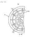
- ribs 50a which extend radially in a radial direction, may be formed on an external side of a pulley half body 50 or, as shown in Figs. 12A and 12B, ribs 51a, which extend radially in a radial direction, and ribs 51b, which extend in a circumferential direction, may be formed on an external side of a pulley half body 51 as e.g. known from JP-A-11-334393.
- the ribs may agitate the air in accordance with rotation of the pulley half body to disturb a flow of cooling air introduced into a transmission case.
- a cooling effect for a V belt cannot be obtained sufficiently.
- an object of the present invention to provide a continuously variable transmission which can increase the cooling effect for the V-belt.
- this object is solved in an inventive manner in that plural radiation fins are formed in substantially concentric cycles on an external surface of the driven pulley.
- the plural radiation fins are formed on the external surface of the driven pulley so as to form substantially concentric circles, rigidity of a pulley half body can be secured, and since each radiation fin takes a circular shape, a cooling effect for the V-belt can be improved without disturbing a flow of the cooling air flowing from the drive pulley side to the driven pulley side.
- circular continuous recesses are formed in substantially concentric cycles between said radiation fins on the external surface of the driven pulley.
- said radiation fins extend parallel to one another in an axial direction on the external surface of a side opposite to a V belt winding surface of the driven pulley.
- At least one of the radiation fins is formed in a part of the driven pulley facing a top position where a winding diameter of the V belt is the minimum.
- At least one of the radiation fins is formed in the part facing the top position of the V-belt, generated heat in the top position part, where a heat load is the largest, can be radiated through the at least one radiation fin, and a radiation property of the pulley half body can be improved.
- the radiation fins are formed concentrically to one another between a radially outermost low position, where a winding diameter of the V-belt is the maximum, and a radially innermost top position, where a winding diameter of the V-belt is the minimum.
- the radiation fins are formed extending from the low position to the top position, a radiation property of the pulley half body can be improved in all operation ranges from an idling state to a maximum speed state, and the V belt can be cooled efficiently.
- an axial extension or height of the radiation fins is larger the closer the radiation fins are located to the top position side.
- the generated heat from the top position part, where a heat load is large, can be radiated efficiently.
- a centrifugal clutch is mounted on a movable pulley half body side of the driven pulley on the driven shaft so as to be adjacent thereto, and an outer end face of the radiation fins is formed so as to substantially coincide with an inner end face of an outer drum of the centrifugal clutch or to be located in the outer drum when the movable pulley half body has moved to a top position.
- the radiation fins can be formed high to increase a surface area thereof without interference with the outer drum, and a radiation property can also be improved from this point.
- said drive pulley is mounted to a drive shaft located on an engine side in a transmission case
- said driven pulley is mounted to a driven shaft located on a rear wheel side, wherein cooling air introduced into the transmission case is directed from the drive pulley side to the driven pulley side.
- a scooter type motorcycle is provided with a continuously variable transmission as described above.
- front and rear as well as left and right mean the front and rear as well as the left and right in the case in which the engine unit is mounted to a vehicle such as, e.g. a scooter type motorcycle, and viewed in a state in which a person such as, e.g. a driver, sits on a seat of such a vehicle.
- a vehicle such as, e.g. a scooter type motorcycle
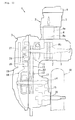
- reference numeral 1 denotes a unit swing type engine unit for a scooter type motorcycle.
- the engine unit 1 is formed by integrating an engine body 2 and a V-belt type continuously variable transmission 3 and is supported so as to be able to swing vertically in substantially a central part of an under bone type body frame (not shown).
- the engine body 2 is arranged with a cylinder shaft oriented substantially in a horizontally front direction, and has a schematic structure in which a cylinder block 4 and a cylinder head 5 are stacked and fastened to a front wall of a crankcase 7 made of aluminum alloy and a head cover 6 is detachably mounted to a front side interface of the cylinder head 5.
- a piston 8a inserted and arranged in a cylinder bore 4a, which is formed in the cylinder block 4, so as to slide freely is coupled to a crankshaft 9, which is arranged so as to be oriented in a vehicle width direction in the crankcase 7, by a connection rod 8b.
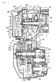
- the continuously variable transmission 3 is a continuously variable transmission in which a transmission body is housed in a transmission case 10 extending rearward on a vehicle left side from a left side part of the engine body 2.
- the transmission body has a schematic structure constituted by winding a V belt 13 around a drive pulley 11, which is mounted to a left end of the crankshaft (drive shaft) 9 located on the engine body 2 side in the transmission case 10, and a driven pulley 12, which is mounted to a driven shaft 14 located on a rear wheel W side.
- rotation of the driven shaft 14 is transmitted to a rear wheel shaft 16 via an intermediate shaft 15 arranged in a gear chamber 20 while being decelerated according to a gear ratio of respective gears 14b, 15a, 15b, and 16a.
- the transmission case 10 includes a case body 17 which is formed integrally with the crankcase 7 and extends to the rear wheel shaft 16, a case cover 18 made of aluminum alloy which is detachably mounted on an outer side (left side) of the case body 17, and a resin cover 19 which covers an external surface of the case cover 18.
- the oil-tight gear chamber 20 is formed by swelling out a rear inner wall 17a of the case body 17 to the rear wheel W side and mounting an inner cover 17b on an inner side of the swelled portion.
- a left journal section 9e of the crankshaft 9 is pivotally supported by a left wall 7a of the crankcase 7 via a bearing 21b.
- a pulley support section 9a which is further on the left side than the left journal section 9e, projects into the transmission case 10a.
- a tip of the pulley support section 9a is pivotally supported by a bearing boss section 18a of the case cover 18 via a bearing 21a and a spacer 9c.
- the bearing boss section 18a supporting the tip of the crankshaft 9 includes an annular ring portion 18c, which supports the bearing 21a, and three legs 18d, which combine and hold the ring portion 18c integrally with a part of the case cover 18 which forms a bottom wall of a blast casing 26 to be described later.
- the drive pulley 11 is mounted to the pulley support section 9a of the crankshaft 9.
- the drive pulley 11 includes a movable pulley half body 11a which is mounted to a slide pipe 11c, which is disposed in the pulley support section 9a so as to rotate therewith, so as to be able to slide in an axial direction thereof and rotate therewith, and a fixed pulley half body 11b which is tightened and fixed to the pulley support section 9a by a nut 9b so as to come into abutment against a tip of the slide pipe 11c.
- reference sign 9d denotes a spacer which fills a gap in the axial direction between the spacer 9c and the fixed pulley half body 11b. These are tightened and fixed to the pulley support section 9a by the nut 9b.
- a weight 11e is provided between a cam plate 11d, which is disposed on a back surface of the movable pulley half body 11a, and a stopper plate 11f, which is fixed to the pulley support section 9a.
- the weight 11e is moved to an outer side in the radial direction by a centrifugal force to move not only the cam plate 11d but also the movable pulley half body 11a. Consequently, an effective diameter of the drive pulley 11 increases, and a vehicle is sped up.
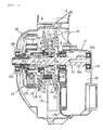
- the driven pulley 12 is mounted to a pulley support section 14a projecting into the transmission case 10 from the gear chamber 20 of the driven shaft 14, and includes a fixed pulley half body 12a, which is disposed in the pulley support section 14a so as to rotate freely and be unable to move in the axial direction, and a movable pulley half body 12b, which is disposed so as to move freely in the axial direction.
- the driven shaft 14 is pivotally supported in a portion on the gear chamber 20 side by the inner wall 17a and the inner cover 17b via the bearings 23a and 23b.
- a tip portion thereof is pivotally supported by a rear wall 18b of the case cover 18 via a bearing 23c.
- a cylindrical slide collar 12c is fixed to an axis part of the fixed pulley half body 12a.
- the slide collar 12c is mounted to the driven shaft 14 via bearings 30a and 30b so as to rotate freely relative to the driven shaft 14.
- a biasing spring 12d is disposed between the boss section 31 and a weight arm 22a of a centrifugal clutch 22, which is described later.
- the movable pulley half body 12b is biased by the biasing spring 12b in a direction in which an effective diameter of the driven pulley 12 increases.
- the centrifugal clutch 22 is provided between an outer end of the slide collar 12c and an outer end of the driven shaft 14.
- This centrifugal clutch 22 has a structure in which the weight arm 22a is locked to a tip of the slide collar 12c, a weight 22b is mounted to the weight arm 22a so as to be able to swing in a radial direction around an axis which is parallel to the driven shaft 14, and a bowl-like outer drum 22c is fixed on the driven shaft 14 side.
- the weight 22b expands outward in the radial direction to come into abutment against an internal circumferential surface of the outer drum 22c, whereby the rotation of the driven pulley 12 is transmitted to the driven shaft 14.
- a blast fan 24 which introduces the air into the transmission case 10 from a front part thereof, boosts and blows the air to portions requiring the air, and exhausts the air from a rear part thereof.
- This blast fan 24 is a fan with a schematic structure in which the periphery of a large number of blast vanes 25 is surrounded by the blast casing 26. Note that the blast fan 24 of this embodiment rotates in a counterclockwise direction viewed from the left of the vehicle (the state shown in Fig. 3).
- the blast vanes 25 are integrally formed on an outer surface of the fixed pulley half body 11b so as to take a radial shape at a predetermined equiangular interval viewed in the axial direction.
- the respective blast vanes 25 are formed such that a part on the center side is deleted when the blast vanes are viewed in an axial perpendicular direction and only a part near an external circumferential edge of the fixed pulley half body 11b is erected to an outer side in the axial direction.
- a ring portion 18c of the bearing boss section 18a is located in the deleted part, whereby expansion of dimensions in the vehicle width direction due to provision of the blast fan 24 is avoided.
- the blast casing 26 has plural sets (three sets in this embodiment) of boost pressure passages 26a, 26b, and 26c which are formed so as to have a wider gap between the blast vanes 25 and the boost pressure passages further on a downstream side in a rotation direction.
- Discharge ports 26d, 26e, and 26f are formed at a downstream end of the respective boost pressure passages 26a to 26c.
- the discharge ports 26d and 26e of the boost pressure passages 26a and 26b at the upper rear part and the lower rear part are arranged so as to be located substantially in the middle between the drive pulley 11 and the driven pulley 12 and generally opposed to the V belt 13 in the parts from the outer side. More specifically, the discharge ports 26d and 26e are formed so as to generally take a rectangular shape, and the discharge port 26d on the upper side is arranged such that a long side of the rectangular intersects the V belt 13. On the other hand, the discharge port 26e on the lower side is arranged such that a long side thereof is substantially parallel to the V belt 12 and a part thereof overlaps the V belt 12.
- the discharge port 26f of the boost pressure passage 26c on the front side thereof is formed so as to discharge cooling wind toward the inner side in the axial direction from a front side edge.
- the cooling wind discharged from the discharge port 26f is supplied to a back side of the movable pulley half body 11a through a guide passage 17c (see Fig. 2) formed at a front end of the case body 17.
- an idling state (reduction ratio is the maximum) and a maximum speed state (reduction ratio is the minimum) of the V belt 13 are indicated by an alternate long and short dash line and an alternate long and two short dashes line, respectively.
- positions of portions 13a and 13b, which are located substantially in the middle of the drive and driven pulleys 11 and 12 of the V belt 13, rarely change in both the idling state and the maximum speed state.
- the discharge ports 26d and 26e are arranged so as to be directed to the portions 13a and 13b, positions of which rarely change in both the idling state and the maximum speed state, of the V belt 13. Consequently, the cooling air can be always blown on the V belt 13 without increasing a size of the discharge ports 26 and 26e so much, that is, while keeping a discharge speed of the cooling air high.
- the boost pressure passages 26a to 26c are constituted by external circumferential sections 18e to 18g and a bottom wall 18h which are formed in the case cover 18, and a top wall 19f which is formed in the resin cover 19. More specifically, the external circumferential sections 18e to 18g forming circumferential edges of the respective boost pressure passages 26a to 26c are formed in the case cover 18 such that the gaps between the external circumferential sections and the blast vanes 25 become larger further on a downstream side in a rotating direction of the drive pulley 11, that is, such that the external circumferential sections generally form tangent lines of the external circumference of the drive pulley 11.
- a portion remaining after forming an opening 18i according to a rotation locus of the blast vanes 25 is the bottom wall 18h.
- the external circumferential sections 18e to 18g forming the boost pressure passage of the case cover 18 are continuous and forms a closed loop as a whole.
- an opening 19a which has a diameter larger than the ring portion 18c of the bearing boss section 18a, and a notch 19b, which prevents interference with the legs 18d, are formed.
- a slit-like space "a" formed between the opening 19a and the ring portion 18c serves as an air passage.
- an element seal rib 19d of a closed loop shape which surrounds the legs 18d of the ring portion 18c, is integrally formed on an external side of the resin cover 19.
- a cover seal rib 19e of a closed loop shape which surrounds the outside of the element seal rib 19d, is integrally formed thereon.
- a seal groove 27a which is formed on an inner surface of an air cleaner element 27, is fit in and mounted to the element seal rib 19d.
- the element 27 is an element in which a rectangular element body 27b is arranged in a part surrounded by the annular seal groove 27a.
- the air is introduced into the blast fan 24 side from a suction port 28a of the air cleaner cover 28 through the element body 27b and further through the slit-like space "a".
- the air is boosted by rotation of the blast vanes 25, discharged toward the middle portions 13a and 13b, positions of which rarely change, of the V belt 13 from the discharge ports 26d and 26e through the boost pressure passages 26a to 26c, and supplied toward the back side of the movable pulley half body 11a from the discharge port 26f through the guide passage 17c, and flows to the driven pulley 12 side through the transmission case 10.
- the blast casing 26, which surrounds the blast vanes 25 provided in the fixed pulley half body 11b of the drive pulley 11, is provided on the transmission case 10 side, and the blast casing 26 has the boost pressure passages 26a to 26c, which are constituted by forming the blast casing 26 such that the gap between the ballast casing 26 and the blast vanes 25 is wider further on the downstream side in the rotation direction, and the discharge ports 26d to 26f are formed at the downstream end of the respective boost pressure passages 26a to 26c.
- cooling air is boosted while flowing through the boost pressure passages 26a to 26c according to the rotation of the blast vanes 25, discharged from the discharge ports 26d to 26f, a blasting efficiency increases, and an amount of cooling air can be increased significantly.
- the discharge ports 26d and 26e of the boost pressure passages 26a and 26b in the upper rear part and the upper lower part are formed so as to discharge the cooling air toward the V belt 13.
- the V belt 13 under thermally severe conditions can be cooled surely.
- the discharge ports 26d and 26e are formed so as to discharge cooling air toward the vicinity of the middle portions 13a and 13b, which intersect each other in both the idling state and the maximum speed state, of the V belt 13.
- the cooling air can be supplied to the V belt 13 in all operation ranges without increasing a size of the discharge ports 26d and 26e, that is, while securing a discharge flow speed of the cooling air.
- the V belt 13 can also be cooled surely from this point.
- cooling air which is discharged from the discharge port 26f of the boost pressure passage 26c on the front side, is supplied toward the back surface of the movable pulley half body 11a, which is located inside the transmission case of the drive pulley 11, through the guide passage 17c.
- the cooling air can be supplied to a portion of the drive pulley 11 which will have highest temperature, and temperature of the portion is prevented from rising abnormally.
- the blast casing 26 is formed by forming the external circumference sections 18e to 18g of the boost pressure passages 26a to 26c in the case cover 18 and covering the external circumferential sections 18e to 18g with the top wall 19f of the resin cover 19.
- the blast casing 26 can be constituted with a simple structure which does not require special components.
- the constitution is adopted in which the bearing boss section 18a, which pivotally supports the outer end of the crankshaft 9, is formed in the case cover 18, and the legs 18d of the bearing boss section 18a is combined integrally with the bottom wall 18h of the blast casing 26.
- the outer end of crankshaft 9 can be pivotally supported surely without increasing the number of components, although the blast casing 26 is provided.
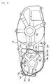
- a pair of front and rear discharge ports 17d and 17e are formed on a bottom wall below the driven pulley 12 of the case body 17.
- the front and rear discharge ports 17d and 17e are arranged on a front side and a rear side across the driven shaft 14 viewed from a plane.
- the cooling air introduced into the transmission case 10 is discharged from the front and rear discharge ports 17d and 17e.
- the fixed pulley half body 12a and the movable pulley half body 12b of the driven pulley 12 are generally disk-shaped half bodies consisting of aluminum die-cast and have an identical shape and an identical size.
- a mounting holes 12f, in which the slide collar 12c and the boss section 31 are mounted, are formed in the axis parts of the pulley half bodies 12a and 12b, and attaching holes 12g for the slide collar 12c and the boss section 31 are formed at circumferential edges of the mounting holes 12f.
- Flat surfaces 12h are formed on external circumferential surfaces of the respective pulley half bodies 12a and 12b by machine work.
- the flat surface 12h of the movable pulley half body 12b is formed as a flank for avoiding interference with the outer drum 22c.
- reference sign 12i is a correction hole for correcting rotation balance of the pulley half bodies 12a and 12b, and is formed if necessary.
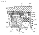
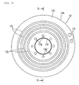
- radiation fins 12j are integrally formed on external sides located on opposite sides of belt winding surfaces of the respective pulley half bodies 12a and 12b so as to form concentric circles.
- circular concentric recesses are formed between said radiation fins 12j on said external surface of the driven pulley, respectively at its half bodies.
- the respective radiation fins 12j are formed extending from a top position (a position indicated by a solid reference symbol line in Fig. 7), where a winding diameter of the V belt 13 is the minimum, to a low position (a position indicated by a reference symbol line consisting of an alternate long and two short dashes), where a winding diameter of the V belt 13 is the maximum. More specifically, the radiation fins 12j, which are located at an inner end in a radial direction of the respective pulley half bodies 12a and 12b, are formed in portions facing the top position of the V belt 13, and the radiation fins 12j, which are located at an outer end in the radial direction, are formed in portions facing the low position of the V belt 13. The remaining radiation fins 12j are formed between both the radiation fins.
- the respective radiation fins 12j are formed so as to project further on an outer side than the flat surface 12h. Consequently, outer end faces 12j'in an axial direction of the respective radiation fins 12j on the movable pulley half body 12b side are located further on an inner side in the axial direction by p than an inner end face 22c' of the outer drum 22c when the pulley half body 12b has moved to the top position.
- the outer end faces 12j' of the respective radiation fins 12j are in an identical position, since the belt winding surface is inclined such that a part thereof further on an inner side in the radial direction is located further on an inner side in the axial direction, a substantial height thereof is larger in a part further on the top position (inner side in the radial direction) side.
- the plural radiation fins 12j are formed on the external sides of the respective pulley half bodies 12a and 12b of the driven pulley 12 so as to take substantially a concentric shape extending in the circumferential direction.
- rigidity of the pulley half bodies 12a and 12b can be secured, and the radiation fins 12j can be prevented from becoming resistance to cooling air flowing from the drive pulley 11 side to the driven pulley 12 side or disturbing the flow of the cooling air, and a cooling effect of the V belt 13 can be improved.
- the radiation fins 12j which are located at an inner end in the radial direction of the respective pulley half bodies 12a and 12b, are formed in the portions facing the top position of the V belt 13 and so as to be the highest.
- the respective radiation fins 12j are arranged extending from the low position to the top position of the V belt 13.
- the radiation property of the respective pulley half bodies 12a and 12b can be improved in all operation ranges from the idling state to the maximum speed state, and the V belt 13 can be cooled efficiently.
- the respective radiation fins 12j are formed such that the outer end faces 12j' are located further on an inner side by p than the inner end face 22c' of the outer drum 22c.
- an amount of projection of the respective radiation fins 12j can be increased to increase a surface area thereof without interfering with the outer drum 22c.
- the radiation property can also be improved from this point.
- a cooling structure for a V- belt type continuously variable transmission which can prevent turbulence of cooling air introduced into a transmission case, such to increase a cooling effect for a V-belt.
- Such a V-belt type continuously variable transmission having a cooling structure is adapted to flow cooling air, which is introduced into a transmission case, from a drive pulley side to a driven pulley side. It comprises plural radiation fins 12j which are formed on external surfaces on opposite sides of belt winding surfaces of respective pulley half bodies 12a and 12b of a driven pulley 12 so as to form substantially a concentric circle.
- Such a continuously variable transmission may be used as part of the drive structure of any motorized vehicle such as for example a scooter type vehicle, an automotive vehicle or a snow vehicle.
Landscapes
- Engineering & Computer Science (AREA)
- General Engineering & Computer Science (AREA)
- Mechanical Engineering (AREA)
- General Details Of Gearings (AREA)
- Transmissions By Endless Flexible Members (AREA)
- Arrangement Of Transmissions (AREA)
- Pulleys (AREA)
Abstract
Description
- Fig. 1
- is a plan view of an engine unit provided with a cooling structure for a V belt continuously variable transmission according to an embodiment of the present invention;
- Fig. 2
- is a sectional plan view of a transmission portion of the embodiment;
- Fig. 3
- is a side view showing a case body of a transmission case of the embodiment;
- Fig. 4
- is a side view showing a case cover of the transmission case;
- Fig. 5
- is a side view showing a resin cover of the transmission case;
- Fig. 6
- is a sectional side view showing a state in which an element is attached of the embodiment (a sectional view along line VI-VI in Fig. 5);
- Fig. 7
- is a sectional plan view on a driven pulley side of the transmission;
- Fig. 8
- is a main part enlarged sectional view of the driven pulley;
- Fig. 9
- is a side view of a movable pulley half body of the driven pulley;
- Fig. 10
- is a sectional view of the movable pulley half body (a sectional view along line X-X in Fig. 9);
- Fig. 11
- is a side view of a conventional general driven pulley;
- Fig. 12a
- is a side view of another conventional general driven pulley; and
- Fig. 12b
- is a sectional view of the conventional pulley along line b-b in Fig. 12a.
Claims (9)
- Continuously variable transmission having a V-belt (13) wound around a drive pulley (11) and a driven pulley (12),
characterized in that
plural radiation fins (12j) are formed in substantially concentric cycles on an external surface of the driven pulley (12). - Continuously variable transmission according to claim 1, characterized in that circular continuous recesses are formed in substantially concentric cycles between said radiation fins (12j) on the external surface of the driven pulley (12).
- Continuously variable transmission according to claim 1 or 2, characterized in that said radiation fins (12j) extend parallel to one another in an axial direction on the external surface of a side opposite to a V-belt winding surface of the driven pulley (12).
- Continuously variable transmission according to at least one of the claims 1 to 3, characterized in that at least one of the radiation fins (12j) is formed in a part of the driven pulley (12) facing a top position where a winding diameter of the V belt (13) is the minimum.
- Continuously variable transmission according to at least one of the claims 1 to 4, characterized in that the radiation fins (12j) are formed concentrically to one another between a radially outermost low position, where a winding diameter of the V-belt (13) is the maximum, and a radially innermost top position, where a winding diameter of the \/-belt (13) is the minimum.
- Continuously variable transmission according to at least one of the claims 1 to 5, characterized in that an axial extension or height of the radiation fins (12j) is larger the closer the radiation fins (12j) are located to the top position side.
- Continuously variable transmission according to at least one of the claims 1 to 6, characterized in that a centrifugal clutch (22) is mounted on a movable pulley half body (12b) side of the driven pulley (12) on the driven shaft (14) so as to be adjacent thereto, and an outer end face of the radiation fins (12j) is formed so as to substantially coincide with an inner end face of an outer drum (22c) of the centrifugal clutch (22) or to be located in the outer drum (22c) when the movable pulley half body (126) has moved to a top position.
- Continuously variable transmission according to at least one of the claims 1 to 7, characterized in that said drive pulley (11) is mounted to a drive shaft (9) located on an engine side in a transmission case (10), and said driven pulley (12) is mounted to a driven shaft (14) located on a rear wheel side, wherein cooling air introduced into the transmission case (10) is directed from the drive pulley side to the driven pulley side.
- Scooter type motorcycle characterized by comprising a continuously variable transmission according to at least one of the claims 1 to 8.
Applications Claiming Priority (2)
| Application Number | Priority Date | Filing Date | Title |
|---|---|---|---|
| JP2003024445A JP4293796B2 (en) | 2003-01-31 | 2003-01-31 | Cooling structure for V-belt type continuously variable transmission |
| JP2003024445 | 2003-01-31 |
Publications (3)
| Publication Number | Publication Date |
|---|---|
| EP1443246A2 true EP1443246A2 (en) | 2004-08-04 |
| EP1443246A3 EP1443246A3 (en) | 2005-02-16 |
| EP1443246B1 EP1443246B1 (en) | 2008-12-03 |
Family
ID=32652924
Family Applications (1)
| Application Number | Title | Priority Date | Filing Date |
|---|---|---|---|
| EP04000873A Expired - Lifetime EP1443246B1 (en) | 2003-01-31 | 2004-01-16 | Continuously variable transmission |
Country Status (6)
| Country | Link |
|---|---|
| EP (1) | EP1443246B1 (en) |
| JP (1) | JP4293796B2 (en) |
| CN (1) | CN100520118C (en) |
| DE (1) | DE602004018046D1 (en) |
| ES (1) | ES2316881T3 (en) |
| TW (1) | TWI253996B (en) |
Cited By (7)
| Publication number | Priority date | Publication date | Assignee | Title |
|---|---|---|---|---|
| EP1650475A1 (en) * | 2004-10-22 | 2006-04-26 | HONDA MOTOR CO., Ltd. | V-belt type automatic transmission |
| EP1621802A3 (en) * | 2004-07-27 | 2007-12-19 | Yamaha Hatsudoki Kabushiki Kaisha | V-belt type continuously variable transmission |
| EP1956269A1 (en) * | 2007-02-09 | 2008-08-13 | Yamaha Hatsudoki Kabushiki Kaisha | Power unit and straddle-type vehicle |
| EP2020534A1 (en) * | 2007-07-26 | 2009-02-04 | Honda Motor Co., Ltd | Power unit |
| ES2331167A1 (en) * | 2007-06-29 | 2009-12-22 | Kwang Yang Motor Co., Ltd | Decorative case for motorcycle transmission box (Machine-translation by Google Translate, not legally binding) |
| EP1624230A3 (en) * | 2004-08-05 | 2010-06-09 | Honda Motor Co., Ltd. | Motor cooling structure for electric vehicle |
| CN103306814A (en) * | 2013-06-28 | 2013-09-18 | 力帆实业(集团)股份有限公司 | Crankshaft link mechanism of motor cycle engine |
Families Citing this family (15)
| Publication number | Priority date | Publication date | Assignee | Title |
|---|---|---|---|---|
| JP2007100945A (en) * | 2005-10-07 | 2007-04-19 | Yamada Seisakusho Co Ltd | V-belt automatic transmission |
| JP4879579B2 (en) * | 2005-12-22 | 2012-02-22 | 本田技研工業株式会社 | Power unit for vehicle |
| JP4801814B2 (en) * | 2006-09-26 | 2011-10-26 | 本田技研工業株式会社 | Cooling structure of continuously variable transmission for vehicle |
| JP4849554B2 (en) * | 2007-01-29 | 2012-01-11 | ヤマハ発動機株式会社 | Engine unit and saddle riding type vehicle equipped with the same |
| CN101344165B (en) * | 2007-07-09 | 2013-03-13 | 光阳工业股份有限公司 | Decoration cover structure of motorcycle transmission case |
| JP5203739B2 (en) * | 2008-02-14 | 2013-06-05 | 本田技研工業株式会社 | Cooling structure for belt type continuously variable transmission |
| JP5301183B2 (en) * | 2008-03-25 | 2013-09-25 | 本田技研工業株式会社 | Power unit |
| JP2010151237A (en) * | 2008-12-25 | 2010-07-08 | Kawasaki Heavy Ind Ltd | V-belt type continuously variable transmission |
| TWI513608B (en) * | 2013-07-18 | 2015-12-21 | Kwang Yang Motor Co | The wind - driven structure of the cooling wind of the vehicle transmission box |
| JP6295721B2 (en) * | 2014-02-28 | 2018-03-20 | 三菱自動車工業株式会社 | Engine valve structure |
| ES2491440B1 (en) * | 2014-05-09 | 2015-05-25 | Automatic Transmission & Innovation, S.A. | Axial transmission system |
| JP6331815B2 (en) * | 2014-07-22 | 2018-05-30 | スズキ株式会社 | Cooling structure for continuously variable transmission |
| CN105782417B (en) * | 2014-12-26 | 2019-11-05 | 光阳工业股份有限公司 | Engine transmission case |
| FR3053394B1 (en) * | 2016-06-30 | 2019-08-09 | Hutchinson | DECOUPLING PULLEY WITH DEPARTURE CLUTCH |
| CA3122836C (en) * | 2017-01-20 | 2025-04-01 | Polaris Industries Inc. | Diagnostic systems and methods of a continuously variable transmission |
Family Cites Families (4)
| Publication number | Priority date | Publication date | Assignee | Title |
|---|---|---|---|---|
| FR2502720B1 (en) * | 1981-03-24 | 1985-10-04 | Motobecane Ateliers | DOUBLE SPEED VARIATOR |
| US4629444A (en) * | 1982-06-01 | 1986-12-16 | Dayco Corporation | Belt pulley and method of making the same |
| JP2909027B2 (en) * | 1996-10-08 | 1999-06-23 | 川崎重工業株式会社 | Cooling structure of vehicle belt type transmission |
| JP4437564B2 (en) * | 1998-05-21 | 2010-03-24 | ヤマハ発動機株式会社 | Engine with V-belt continuously variable transmission |
-
2003
- 2003-01-31 JP JP2003024445A patent/JP4293796B2/en not_active Expired - Lifetime
-
2004
- 2004-01-16 ES ES04000873T patent/ES2316881T3/en not_active Expired - Lifetime
- 2004-01-16 EP EP04000873A patent/EP1443246B1/en not_active Expired - Lifetime
- 2004-01-16 DE DE602004018046T patent/DE602004018046D1/en not_active Expired - Lifetime
- 2004-01-28 TW TW093101867A patent/TWI253996B/en not_active IP Right Cessation
- 2004-01-30 CN CNB2004100025433A patent/CN100520118C/en not_active Expired - Lifetime
Cited By (11)
| Publication number | Priority date | Publication date | Assignee | Title |
|---|---|---|---|---|
| EP1621802A3 (en) * | 2004-07-27 | 2007-12-19 | Yamaha Hatsudoki Kabushiki Kaisha | V-belt type continuously variable transmission |
| EP1624230A3 (en) * | 2004-08-05 | 2010-06-09 | Honda Motor Co., Ltd. | Motor cooling structure for electric vehicle |
| EP1650475A1 (en) * | 2004-10-22 | 2006-04-26 | HONDA MOTOR CO., Ltd. | V-belt type automatic transmission |
| EP1826113A1 (en) * | 2004-10-22 | 2007-08-29 | HONDA MOTOR CO., Ltd. | V-belt type automatic transmission |
| EP1956269A1 (en) * | 2007-02-09 | 2008-08-13 | Yamaha Hatsudoki Kabushiki Kaisha | Power unit and straddle-type vehicle |
| US8371972B2 (en) | 2007-02-09 | 2013-02-12 | Yamaha Hatsudoki Kabushiki Kaisha | Power unit and straddle-type vehicle |
| ES2331167A1 (en) * | 2007-06-29 | 2009-12-22 | Kwang Yang Motor Co., Ltd | Decorative case for motorcycle transmission box (Machine-translation by Google Translate, not legally binding) |
| ES2331167B1 (en) * | 2007-06-29 | 2010-09-21 | Kwang Yang Motor Co., Ltd | DECORATIVE HOUSING FOR MOTORCYCLE TRANSMISSION CASE. |
| EP2020534A1 (en) * | 2007-07-26 | 2009-02-04 | Honda Motor Co., Ltd | Power unit |
| CN103306814A (en) * | 2013-06-28 | 2013-09-18 | 力帆实业(集团)股份有限公司 | Crankshaft link mechanism of motor cycle engine |
| CN103306814B (en) * | 2013-06-28 | 2015-09-30 | 力帆实业(集团)股份有限公司 | Motorcycle engine crank connecting rod mechanism |
Also Published As
| Publication number | Publication date |
|---|---|
| CN1519494A (en) | 2004-08-11 |
| CN100520118C (en) | 2009-07-29 |
| JP2004232805A (en) | 2004-08-19 |
| ES2316881T3 (en) | 2009-04-16 |
| EP1443246B1 (en) | 2008-12-03 |
| TW200427595A (en) | 2004-12-16 |
| JP4293796B2 (en) | 2009-07-08 |
| DE602004018046D1 (en) | 2009-01-15 |
| EP1443246A3 (en) | 2005-02-16 |
| TWI253996B (en) | 2006-05-01 |
Similar Documents
| Publication | Publication Date | Title |
|---|---|---|
| EP1443246B1 (en) | Continuously variable transmission | |
| US6220207B1 (en) | Engine cooling apparatus | |
| US5224459A (en) | Supercharger | |
| JP4359040B2 (en) | Cooling structure for V-belt type continuously variable transmission | |
| US20140294641A1 (en) | Scroll Fluid Machine | |
| JPH01267303A (en) | variable capacity turbine | |
| US7047914B2 (en) | Internal combustion engine combination with direct camshaft driven coolant pump | |
| JPWO2018011970A1 (en) | Motor integrated fluid machine | |
| CN106089726B (en) | Compressor | |
| US10630144B2 (en) | Electric motor support mechanism, compressor, and turbocharger | |
| JP3208295B2 (en) | Internal combustion engine cooling system | |
| CN106574619A (en) | Scroll-type fluid machine and maintenance method for same | |
| US20070217907A1 (en) | Water pump with housing/impeller to enhance seal performance | |
| US20060292020A1 (en) | Cooling fan | |
| JP3750791B2 (en) | Engine with torque converter | |
| JP3084841B2 (en) | Water-cooled bearing housing structure for turbocharger | |
| JP2967369B2 (en) | Water pump | |
| JP4693871B2 (en) | Motorcycle engine | |
| JP5308234B2 (en) | Cooling fan device for construction machinery | |
| JP4305066B2 (en) | Water pump for internal combustion engine and mounting structure thereof | |
| CA2492764C (en) | Internal combustion engine combination with direct camshaft driven coolant pump | |
| JP2000045921A (en) | Motorcycle engine | |
| JPH0674045A (en) | Engine cooling mechanism | |
| JPH09144673A (en) | Scroll type fluid machine | |
| JP2004003409A (en) | Blower using heat |
Legal Events
| Date | Code | Title | Description |
|---|---|---|---|
| PUAI | Public reference made under article 153(3) epc to a published international application that has entered the european phase |
Free format text: ORIGINAL CODE: 0009012 |
|
| AK | Designated contracting states |
Kind code of ref document: A2 Designated state(s): AT BE BG CH CY CZ DE DK EE ES FI FR GB GR HU IE IT LI LU MC NL PT RO SE SI SK TR |
|
| AX | Request for extension of the european patent |
Extension state: AL LT LV MK |
|
| PUAL | Search report despatched |
Free format text: ORIGINAL CODE: 0009013 |
|
| AK | Designated contracting states |
Kind code of ref document: A3 Designated state(s): AT BE BG CH CY CZ DE DK EE ES FI FR GB GR HU IE IT LI LU MC NL PT RO SE SI SK TR |
|
| AX | Request for extension of the european patent |
Extension state: AL LT LV MK |
|
| 17P | Request for examination filed |
Effective date: 20050121 |
|
| AKX | Designation fees paid |
Designated state(s): DE ES FR GB IT |
|
| 17Q | First examination report despatched |
Effective date: 20070202 |
|
| GRAP | Despatch of communication of intention to grant a patent |
Free format text: ORIGINAL CODE: EPIDOSNIGR1 |
|
| GRAS | Grant fee paid |
Free format text: ORIGINAL CODE: EPIDOSNIGR3 |
|
| GRAS | Grant fee paid |
Free format text: ORIGINAL CODE: EPIDOSNIGR3 |
|
| GRAA | (expected) grant |
Free format text: ORIGINAL CODE: 0009210 |
|
| AK | Designated contracting states |
Kind code of ref document: B1 Designated state(s): DE ES FR GB IT |
|
| REG | Reference to a national code |
Ref country code: GB Ref legal event code: FG4D |
|
| REF | Corresponds to: |
Ref document number: 602004018046 Country of ref document: DE Date of ref document: 20090115 Kind code of ref document: P |
|
| REG | Reference to a national code |
Ref country code: ES Ref legal event code: FG2A Ref document number: 2316881 Country of ref document: ES Kind code of ref document: T3 |
|
| PLBE | No opposition filed within time limit |
Free format text: ORIGINAL CODE: 0009261 |
|
| STAA | Information on the status of an ep patent application or granted ep patent |
Free format text: STATUS: NO OPPOSITION FILED WITHIN TIME LIMIT |
|
| 26N | No opposition filed |
Effective date: 20090904 |
|
| GBPC | Gb: european patent ceased through non-payment of renewal fee |
Effective date: 20090303 |
|
| REG | Reference to a national code |
Ref country code: FR Ref legal event code: ST Effective date: 20091030 |
|
| PG25 | Lapsed in a contracting state [announced via postgrant information from national office to epo] |
Ref country code: GB Free format text: LAPSE BECAUSE OF NON-PAYMENT OF DUE FEES Effective date: 20090303 Ref country code: FR Free format text: LAPSE BECAUSE OF NON-PAYMENT OF DUE FEES Effective date: 20090203 |
|
| PGFP | Annual fee paid to national office [announced via postgrant information from national office to epo] |
Ref country code: ES Payment date: 20230330 Year of fee payment: 20 |
|
| PGFP | Annual fee paid to national office [announced via postgrant information from national office to epo] |
Ref country code: IT Payment date: 20230120 Year of fee payment: 20 Ref country code: DE Payment date: 20230123 Year of fee payment: 20 |
|
| P01 | Opt-out of the competence of the unified patent court (upc) registered |
Effective date: 20230527 |
|
| REG | Reference to a national code |
Ref country code: DE Ref legal event code: R071 Ref document number: 602004018046 Country of ref document: DE |
|
| REG | Reference to a national code |
Ref country code: ES Ref legal event code: FD2A Effective date: 20240126 |
|
| PG25 | Lapsed in a contracting state [announced via postgrant information from national office to epo] |
Ref country code: ES Free format text: LAPSE BECAUSE OF EXPIRATION OF PROTECTION Effective date: 20240117 |
|
| PG25 | Lapsed in a contracting state [announced via postgrant information from national office to epo] |
Ref country code: ES Free format text: LAPSE BECAUSE OF EXPIRATION OF PROTECTION Effective date: 20240117 |