EP1443228A1 - Bearing device for supporting pinion shaft - Google Patents
Bearing device for supporting pinion shaft Download PDFInfo
- Publication number
- EP1443228A1 EP1443228A1 EP02778068A EP02778068A EP1443228A1 EP 1443228 A1 EP1443228 A1 EP 1443228A1 EP 02778068 A EP02778068 A EP 02778068A EP 02778068 A EP02778068 A EP 02778068A EP 1443228 A1 EP1443228 A1 EP 1443228A1
- Authority
- EP
- European Patent Office
- Prior art keywords
- tilt
- contact rolling
- bearing
- pinion
- pinion shaft
- Prior art date
- Legal status (The legal status is an assumption and is not a legal conclusion. Google has not performed a legal analysis and makes no representation as to the accuracy of the status listed.)
- Granted
Links
- 238000005096 rolling process Methods 0.000 claims abstract description 122
- 239000004519 grease Substances 0.000 claims abstract description 23
- 230000002093 peripheral effect Effects 0.000 claims abstract description 22
- 230000036316 preload Effects 0.000 claims abstract description 12
- 230000009471 action Effects 0.000 claims abstract description 8
- 238000007789 sealing Methods 0.000 claims description 5
- 125000006850 spacer group Chemical group 0.000 claims description 4
- 239000003921 oil Substances 0.000 description 25
- 230000000717 retained effect Effects 0.000 description 12
- 230000008859 change Effects 0.000 description 11
- 230000007246 mechanism Effects 0.000 description 11
- 238000005461 lubrication Methods 0.000 description 6
- 230000004048 modification Effects 0.000 description 6
- 238000012986 modification Methods 0.000 description 6
- 238000010168 coupling process Methods 0.000 description 4
- 238000005859 coupling reaction Methods 0.000 description 4
- 230000000694 effects Effects 0.000 description 4
- 238000012423 maintenance Methods 0.000 description 4
- 238000004519 manufacturing process Methods 0.000 description 4
- 238000010992 reflux Methods 0.000 description 4
- 229920000800 acrylic rubber Polymers 0.000 description 3
- 239000012208 gear oil Substances 0.000 description 3
- 229920000058 polyacrylate Polymers 0.000 description 3
- 238000012546 transfer Methods 0.000 description 3
- 239000002199 base oil Substances 0.000 description 2
- 239000011248 coating agent Substances 0.000 description 2
- 238000000576 coating method Methods 0.000 description 2
- 238000004891 communication Methods 0.000 description 2
- 150000002148 esters Chemical class 0.000 description 2
- 238000012856 packing Methods 0.000 description 2
- 230000004044 response Effects 0.000 description 2
- 239000002562 thickening agent Substances 0.000 description 2
- XMKLTEGSALONPH-UHFFFAOYSA-N 1,2,4,5-tetrazinane-3,6-dione Chemical compound O=C1NNC(=O)NN1 XMKLTEGSALONPH-UHFFFAOYSA-N 0.000 description 1
- VGGSQFUCUMXWEO-UHFFFAOYSA-N Ethene Chemical compound C=C VGGSQFUCUMXWEO-UHFFFAOYSA-N 0.000 description 1
- 239000005977 Ethylene Substances 0.000 description 1
- WHXSMMKQMYFTQS-UHFFFAOYSA-N Lithium Chemical compound [Li] WHXSMMKQMYFTQS-UHFFFAOYSA-N 0.000 description 1
- 125000005396 acrylic acid ester group Chemical group 0.000 description 1
- 230000004323 axial length Effects 0.000 description 1
- 230000015572 biosynthetic process Effects 0.000 description 1
- 229920001577 copolymer Polymers 0.000 description 1
- 229920006229 ethylene acrylic elastomer Polymers 0.000 description 1
- 229910052744 lithium Inorganic materials 0.000 description 1
- 239000000463 material Substances 0.000 description 1
- 239000002480 mineral oil Substances 0.000 description 1
- 235000010446 mineral oil Nutrition 0.000 description 1
- 230000000149 penetrating effect Effects 0.000 description 1
- 230000035515 penetration Effects 0.000 description 1
- 229920013639 polyalphaolefin Polymers 0.000 description 1
- 230000009467 reduction Effects 0.000 description 1
- 239000000344 soap Substances 0.000 description 1
- 238000001179 sorption measurement Methods 0.000 description 1
- 238000009423 ventilation Methods 0.000 description 1
- XLYOFNOQVPJJNP-UHFFFAOYSA-N water Substances O XLYOFNOQVPJJNP-UHFFFAOYSA-N 0.000 description 1
Images


Classifications
-
- F—MECHANICAL ENGINEERING; LIGHTING; HEATING; WEAPONS; BLASTING
- F16—ENGINEERING ELEMENTS AND UNITS; GENERAL MEASURES FOR PRODUCING AND MAINTAINING EFFECTIVE FUNCTIONING OF MACHINES OR INSTALLATIONS; THERMAL INSULATION IN GENERAL
- F16H—GEARING
- F16H57/00—General details of gearing
- F16H57/02—Gearboxes; Mounting gearing therein
- F16H57/021—Shaft support structures, e.g. partition walls, bearing eyes, casing walls or covers with bearings
-
- F—MECHANICAL ENGINEERING; LIGHTING; HEATING; WEAPONS; BLASTING
- F16—ENGINEERING ELEMENTS AND UNITS; GENERAL MEASURES FOR PRODUCING AND MAINTAINING EFFECTIVE FUNCTIONING OF MACHINES OR INSTALLATIONS; THERMAL INSULATION IN GENERAL
- F16C—SHAFTS; FLEXIBLE SHAFTS; ELEMENTS OR CRANKSHAFT MECHANISMS; ROTARY BODIES OTHER THAN GEARING ELEMENTS; BEARINGS
- F16C19/00—Bearings with rolling contact, for exclusively rotary movement
- F16C19/02—Bearings with rolling contact, for exclusively rotary movement with bearing balls essentially of the same size in one or more circular rows
- F16C19/14—Bearings with rolling contact, for exclusively rotary movement with bearing balls essentially of the same size in one or more circular rows for both radial and axial load
- F16C19/16—Bearings with rolling contact, for exclusively rotary movement with bearing balls essentially of the same size in one or more circular rows for both radial and axial load with a single row of balls
- F16C19/163—Bearings with rolling contact, for exclusively rotary movement with bearing balls essentially of the same size in one or more circular rows for both radial and axial load with a single row of balls with angular contact
-
- F—MECHANICAL ENGINEERING; LIGHTING; HEATING; WEAPONS; BLASTING
- F16—ENGINEERING ELEMENTS AND UNITS; GENERAL MEASURES FOR PRODUCING AND MAINTAINING EFFECTIVE FUNCTIONING OF MACHINES OR INSTALLATIONS; THERMAL INSULATION IN GENERAL
- F16C—SHAFTS; FLEXIBLE SHAFTS; ELEMENTS OR CRANKSHAFT MECHANISMS; ROTARY BODIES OTHER THAN GEARING ELEMENTS; BEARINGS
- F16C19/00—Bearings with rolling contact, for exclusively rotary movement
- F16C19/02—Bearings with rolling contact, for exclusively rotary movement with bearing balls essentially of the same size in one or more circular rows
- F16C19/14—Bearings with rolling contact, for exclusively rotary movement with bearing balls essentially of the same size in one or more circular rows for both radial and axial load
- F16C19/18—Bearings with rolling contact, for exclusively rotary movement with bearing balls essentially of the same size in one or more circular rows for both radial and axial load with two or more rows of balls
- F16C19/181—Bearings with rolling contact, for exclusively rotary movement with bearing balls essentially of the same size in one or more circular rows for both radial and axial load with two or more rows of balls with angular contact
- F16C19/182—Bearings with rolling contact, for exclusively rotary movement with bearing balls essentially of the same size in one or more circular rows for both radial and axial load with two or more rows of balls with angular contact in tandem arrangement
-
- F—MECHANICAL ENGINEERING; LIGHTING; HEATING; WEAPONS; BLASTING
- F16—ENGINEERING ELEMENTS AND UNITS; GENERAL MEASURES FOR PRODUCING AND MAINTAINING EFFECTIVE FUNCTIONING OF MACHINES OR INSTALLATIONS; THERMAL INSULATION IN GENERAL
- F16C—SHAFTS; FLEXIBLE SHAFTS; ELEMENTS OR CRANKSHAFT MECHANISMS; ROTARY BODIES OTHER THAN GEARING ELEMENTS; BEARINGS
- F16C19/00—Bearings with rolling contact, for exclusively rotary movement
- F16C19/22—Bearings with rolling contact, for exclusively rotary movement with bearing rollers essentially of the same size in one or more circular rows, e.g. needle bearings
- F16C19/34—Bearings with rolling contact, for exclusively rotary movement with bearing rollers essentially of the same size in one or more circular rows, e.g. needle bearings for both radial and axial load
- F16C19/36—Bearings with rolling contact, for exclusively rotary movement with bearing rollers essentially of the same size in one or more circular rows, e.g. needle bearings for both radial and axial load with a single row of rollers
- F16C19/364—Bearings with rolling contact, for exclusively rotary movement with bearing rollers essentially of the same size in one or more circular rows, e.g. needle bearings for both radial and axial load with a single row of rollers with tapered rollers, i.e. rollers having essentially the shape of a truncated cone
-
- F—MECHANICAL ENGINEERING; LIGHTING; HEATING; WEAPONS; BLASTING
- F16—ENGINEERING ELEMENTS AND UNITS; GENERAL MEASURES FOR PRODUCING AND MAINTAINING EFFECTIVE FUNCTIONING OF MACHINES OR INSTALLATIONS; THERMAL INSULATION IN GENERAL
- F16C—SHAFTS; FLEXIBLE SHAFTS; ELEMENTS OR CRANKSHAFT MECHANISMS; ROTARY BODIES OTHER THAN GEARING ELEMENTS; BEARINGS
- F16C19/00—Bearings with rolling contact, for exclusively rotary movement
- F16C19/49—Bearings with both balls and rollers
- F16C19/492—Bearings with both balls and rollers with two or more rows with angular contact
-
- F—MECHANICAL ENGINEERING; LIGHTING; HEATING; WEAPONS; BLASTING
- F16—ENGINEERING ELEMENTS AND UNITS; GENERAL MEASURES FOR PRODUCING AND MAINTAINING EFFECTIVE FUNCTIONING OF MACHINES OR INSTALLATIONS; THERMAL INSULATION IN GENERAL
- F16C—SHAFTS; FLEXIBLE SHAFTS; ELEMENTS OR CRANKSHAFT MECHANISMS; ROTARY BODIES OTHER THAN GEARING ELEMENTS; BEARINGS
- F16C19/00—Bearings with rolling contact, for exclusively rotary movement
- F16C19/54—Systems consisting of a plurality of bearings with rolling friction
- F16C19/546—Systems with spaced apart rolling bearings including at least one angular contact bearing
- F16C19/547—Systems with spaced apart rolling bearings including at least one angular contact bearing with two angular contact rolling bearings
- F16C19/548—Systems with spaced apart rolling bearings including at least one angular contact bearing with two angular contact rolling bearings in O-arrangement
-
- F—MECHANICAL ENGINEERING; LIGHTING; HEATING; WEAPONS; BLASTING
- F16—ENGINEERING ELEMENTS AND UNITS; GENERAL MEASURES FOR PRODUCING AND MAINTAINING EFFECTIVE FUNCTIONING OF MACHINES OR INSTALLATIONS; THERMAL INSULATION IN GENERAL
- F16C—SHAFTS; FLEXIBLE SHAFTS; ELEMENTS OR CRANKSHAFT MECHANISMS; ROTARY BODIES OTHER THAN GEARING ELEMENTS; BEARINGS
- F16C33/00—Parts of bearings; Special methods for making bearings or parts thereof
- F16C33/30—Parts of ball or roller bearings
- F16C33/66—Special parts or details in view of lubrication
- F16C33/6603—Special parts or details in view of lubrication with grease as lubricant
- F16C33/6607—Retaining the grease in or near the bearing
- F16C33/6611—Retaining the grease in or near the bearing in a porous or resinous body, e.g. a cage impregnated with the grease
-
- F—MECHANICAL ENGINEERING; LIGHTING; HEATING; WEAPONS; BLASTING
- F16—ENGINEERING ELEMENTS AND UNITS; GENERAL MEASURES FOR PRODUCING AND MAINTAINING EFFECTIVE FUNCTIONING OF MACHINES OR INSTALLATIONS; THERMAL INSULATION IN GENERAL
- F16C—SHAFTS; FLEXIBLE SHAFTS; ELEMENTS OR CRANKSHAFT MECHANISMS; ROTARY BODIES OTHER THAN GEARING ELEMENTS; BEARINGS
- F16C33/00—Parts of bearings; Special methods for making bearings or parts thereof
- F16C33/30—Parts of ball or roller bearings
- F16C33/66—Special parts or details in view of lubrication
- F16C33/6603—Special parts or details in view of lubrication with grease as lubricant
- F16C33/6607—Retaining the grease in or near the bearing
- F16C33/6614—Retaining the grease in or near the bearing in recesses or cavities provided in retainers, races or rolling elements
-
- F—MECHANICAL ENGINEERING; LIGHTING; HEATING; WEAPONS; BLASTING
- F16—ENGINEERING ELEMENTS AND UNITS; GENERAL MEASURES FOR PRODUCING AND MAINTAINING EFFECTIVE FUNCTIONING OF MACHINES OR INSTALLATIONS; THERMAL INSULATION IN GENERAL
- F16C—SHAFTS; FLEXIBLE SHAFTS; ELEMENTS OR CRANKSHAFT MECHANISMS; ROTARY BODIES OTHER THAN GEARING ELEMENTS; BEARINGS
- F16C33/00—Parts of bearings; Special methods for making bearings or parts thereof
- F16C33/30—Parts of ball or roller bearings
- F16C33/66—Special parts or details in view of lubrication
- F16C33/6603—Special parts or details in view of lubrication with grease as lubricant
- F16C33/6622—Details of supply and/or removal of the grease, e.g. purging grease
-
- F—MECHANICAL ENGINEERING; LIGHTING; HEATING; WEAPONS; BLASTING
- F16—ENGINEERING ELEMENTS AND UNITS; GENERAL MEASURES FOR PRODUCING AND MAINTAINING EFFECTIVE FUNCTIONING OF MACHINES OR INSTALLATIONS; THERMAL INSULATION IN GENERAL
- F16C—SHAFTS; FLEXIBLE SHAFTS; ELEMENTS OR CRANKSHAFT MECHANISMS; ROTARY BODIES OTHER THAN GEARING ELEMENTS; BEARINGS
- F16C33/00—Parts of bearings; Special methods for making bearings or parts thereof
- F16C33/30—Parts of ball or roller bearings
- F16C33/66—Special parts or details in view of lubrication
- F16C33/6603—Special parts or details in view of lubrication with grease as lubricant
- F16C33/6633—Grease properties or compositions, e.g. rheological properties
-
- F—MECHANICAL ENGINEERING; LIGHTING; HEATING; WEAPONS; BLASTING
- F16—ENGINEERING ELEMENTS AND UNITS; GENERAL MEASURES FOR PRODUCING AND MAINTAINING EFFECTIVE FUNCTIONING OF MACHINES OR INSTALLATIONS; THERMAL INSULATION IN GENERAL
- F16C—SHAFTS; FLEXIBLE SHAFTS; ELEMENTS OR CRANKSHAFT MECHANISMS; ROTARY BODIES OTHER THAN GEARING ELEMENTS; BEARINGS
- F16C33/00—Parts of bearings; Special methods for making bearings or parts thereof
- F16C33/72—Sealings
- F16C33/76—Sealings of ball or roller bearings
- F16C33/78—Sealings of ball or roller bearings with a diaphragm, disc, or ring, with or without resilient members
- F16C33/7869—Sealings of ball or roller bearings with a diaphragm, disc, or ring, with or without resilient members mounted with a cylindrical portion to the inner surface of the outer race and having a radial portion extending inward
-
- F—MECHANICAL ENGINEERING; LIGHTING; HEATING; WEAPONS; BLASTING
- F16—ENGINEERING ELEMENTS AND UNITS; GENERAL MEASURES FOR PRODUCING AND MAINTAINING EFFECTIVE FUNCTIONING OF MACHINES OR INSTALLATIONS; THERMAL INSULATION IN GENERAL
- F16H—GEARING
- F16H57/00—General details of gearing
- F16H57/02—Gearboxes; Mounting gearing therein
- F16H57/037—Gearboxes for accommodating differential gearings
-
- F—MECHANICAL ENGINEERING; LIGHTING; HEATING; WEAPONS; BLASTING
- F16—ENGINEERING ELEMENTS AND UNITS; GENERAL MEASURES FOR PRODUCING AND MAINTAINING EFFECTIVE FUNCTIONING OF MACHINES OR INSTALLATIONS; THERMAL INSULATION IN GENERAL
- F16C—SHAFTS; FLEXIBLE SHAFTS; ELEMENTS OR CRANKSHAFT MECHANISMS; ROTARY BODIES OTHER THAN GEARING ELEMENTS; BEARINGS
- F16C19/00—Bearings with rolling contact, for exclusively rotary movement
- F16C19/54—Systems consisting of a plurality of bearings with rolling friction
- F16C19/541—Systems consisting of juxtaposed rolling bearings including at least one angular contact bearing
- F16C19/542—Systems consisting of juxtaposed rolling bearings including at least one angular contact bearing with two rolling bearings with angular contact
-
- F—MECHANICAL ENGINEERING; LIGHTING; HEATING; WEAPONS; BLASTING
- F16—ENGINEERING ELEMENTS AND UNITS; GENERAL MEASURES FOR PRODUCING AND MAINTAINING EFFECTIVE FUNCTIONING OF MACHINES OR INSTALLATIONS; THERMAL INSULATION IN GENERAL
- F16C—SHAFTS; FLEXIBLE SHAFTS; ELEMENTS OR CRANKSHAFT MECHANISMS; ROTARY BODIES OTHER THAN GEARING ELEMENTS; BEARINGS
- F16C2240/00—Specified values or numerical ranges of parameters; Relations between them
- F16C2240/40—Linear dimensions, e.g. length, radius, thickness, gap
- F16C2240/70—Diameters; Radii
- F16C2240/80—Pitch circle diameters [PCD]
-
- F—MECHANICAL ENGINEERING; LIGHTING; HEATING; WEAPONS; BLASTING
- F16—ENGINEERING ELEMENTS AND UNITS; GENERAL MEASURES FOR PRODUCING AND MAINTAINING EFFECTIVE FUNCTIONING OF MACHINES OR INSTALLATIONS; THERMAL INSULATION IN GENERAL
- F16C—SHAFTS; FLEXIBLE SHAFTS; ELEMENTS OR CRANKSHAFT MECHANISMS; ROTARY BODIES OTHER THAN GEARING ELEMENTS; BEARINGS
- F16C2361/00—Apparatus or articles in engineering in general
- F16C2361/61—Toothed gear systems, e.g. support of pinion shafts
-
- F—MECHANICAL ENGINEERING; LIGHTING; HEATING; WEAPONS; BLASTING
- F16—ENGINEERING ELEMENTS AND UNITS; GENERAL MEASURES FOR PRODUCING AND MAINTAINING EFFECTIVE FUNCTIONING OF MACHINES OR INSTALLATIONS; THERMAL INSULATION IN GENERAL
- F16C—SHAFTS; FLEXIBLE SHAFTS; ELEMENTS OR CRANKSHAFT MECHANISMS; ROTARY BODIES OTHER THAN GEARING ELEMENTS; BEARINGS
- F16C35/00—Rigid support of bearing units; Housings, e.g. caps, covers
- F16C35/04—Rigid support of bearing units; Housings, e.g. caps, covers in the case of ball or roller bearings
- F16C35/06—Mounting or dismounting of ball or roller bearings; Fixing them onto shaft or in housing
- F16C35/067—Fixing them in a housing
-
- F—MECHANICAL ENGINEERING; LIGHTING; HEATING; WEAPONS; BLASTING
- F16—ENGINEERING ELEMENTS AND UNITS; GENERAL MEASURES FOR PRODUCING AND MAINTAINING EFFECTIVE FUNCTIONING OF MACHINES OR INSTALLATIONS; THERMAL INSULATION IN GENERAL
- F16H—GEARING
- F16H1/00—Toothed gearings for conveying rotary motion
- F16H1/02—Toothed gearings for conveying rotary motion without gears having orbital motion
- F16H1/04—Toothed gearings for conveying rotary motion without gears having orbital motion involving only two intermeshing members
- F16H1/12—Toothed gearings for conveying rotary motion without gears having orbital motion involving only two intermeshing members with non-parallel axes
- F16H1/14—Toothed gearings for conveying rotary motion without gears having orbital motion involving only two intermeshing members with non-parallel axes comprising conical gears only
- F16H1/145—Toothed gearings for conveying rotary motion without gears having orbital motion involving only two intermeshing members with non-parallel axes comprising conical gears only with offset axes, e.g. hypoïd gearings
-
- F—MECHANICAL ENGINEERING; LIGHTING; HEATING; WEAPONS; BLASTING
- F16—ENGINEERING ELEMENTS AND UNITS; GENERAL MEASURES FOR PRODUCING AND MAINTAINING EFFECTIVE FUNCTIONING OF MACHINES OR INSTALLATIONS; THERMAL INSULATION IN GENERAL
- F16H—GEARING
- F16H48/00—Differential gearings
- F16H48/38—Constructional details
- F16H48/42—Constructional details characterised by features of the input shafts, e.g. mounting of drive gears thereon
- F16H2048/423—Constructional details characterised by features of the input shafts, e.g. mounting of drive gears thereon characterised by bearing arrangement
Definitions
- the present invention relates to a bearing device for supporting a pinion shaft so as to freely rotate, more particularly to a bearing device for supporting a pinion shaft comprised of a pair of tilt-contact rolling bearings installed in axial proximity and lubricated with grease.
- Fig. 12 The structure of a conventional differential device is shown in Fig. 12.
- a differential speed change mechanism 2 for differentially gearing right and left wheels, a pinion gear 3, a pinion shaft 4, and tapered roller bearings 50 and 60 for supporting the pinion shaft 4 so as to freely rotate, which are housed in a differential case 1.
- the pinion gear 3 is engaged with a ring gear 2a of the differential speed change mechanism 2 and is integral with the pinion shaft 4 at the inner end portion thereof.
- the pinion shaft 4 is supported, so as to freely rotate, on the inner side of the differential case 1 by the single row tapered roller bearings 50 and 60 of rear-surface-coupling type.
- a companion flange 7 At the outer end portion of the pinion shaft 4 is provided.
- the tapered roller bearings 50 and 60 are respectively mounted to the inner peripheral surfaces of bearing-mounting annular walls 13 and 14 formed in a forged bearing case portion 1a of the differential case 1.
- the companion-flange-side tapered roller bearings 50 are installed from a small-diameter-side opening portion of the bearing case portion 1a.
- the pinion-gear-side tapered roller bearings 60 are installedfrom a large-diameter-side opening portion of the bearing case portion 1a.
- Spacers 8 for positioning are interposed between the tapered roller bearings 50 and 60.
- the tapered roller bearings 50 and 60 are fixed by screwing a nut 15 into the outer and portion of the pinion shaft 4 and fastening it into the companion flange 7, thereby applying a sufficient preload between the pinion gear 3 and the companion flange 7.
- Lubrication oil is stored in the differential case 1 at a level L in the non-operating condition.
- the oil is splashed in response to the rotation of the gear ring 2a during operation, guided to the tapered roller bearings 50 and 60 through an oil introducing path 11 formed between the annular walls 13 and 14 in the bearing case portion 1a, and returned through an oil reflux path (not shown).
- oil seals 9 Between the outer peripheral surface of the pinion shaft 4 on the outer end portion side thereof and the inner peripheral surface of the bearing case portion 1a are mounted oil seals 9 for preventing oil leakage, and further seal protection cups 10 for concealing the oil seals 9.
- a main object of the present invention is to provide a bearing device for supporting a pinion shaft capable of reducing running torque to improve the efficiency of the device, suppressing the increase of the torque due to a resistance caused by agitated oil, reducing the device in size and weight, and improving the life of the bearing.
- the present invention relates to a bearing device for supporting a pinion shaft, wherein a pinion gear is provided on one end side and a connecting flange on another end side, so as to freely rotate with respect to a case.
- the bearing device has a first tilt-contact rolling bearing provided on the connecting-flange-side outer peripheral surface of the pinion shaft and a second tilt-contact rolling bearing comprising an angular ball bearing provided on the pinion-gear-side outer peripheral surface of the pinion shaft.
- the lines of action of the first and second tilt-contact rolling bearings intersect with one another on an outer diameter side; the connecting-flange-side end portion of the first tilt-contact rolling bearing and the pinion-gear-side end portion of the second tilt-contact rolling bearing are respectively sealed with seal members; the sealed space between the seal members is infilled with grease; and the connecting flange is fastened in the pinion-gear direction thereby applying a preload to the first and second tilt-contact rolling bearings.
- the bearing device for supporting a pinion shaft according to the present invention is applied to a differential device, transfer device or the like.
- the connecting flange When applied to, for example, a differential device, the connecting flange constitutes a companion flange coupled with a propeller shaft, and when applied to a transfer device, the connecting flange constitutes an output flange coupled with a rear wheel differential.
- first tilt-contact rolling bearing is employed a tandem angular ball bearing having connecting-flange-side single or double rows of balls disposed radially outward or various types of tilt-contact rolling bearings such as a tapered roller bearing, or the like.
- the second tilt-contact rolling bearing is employed a tandem angular ball bearing having pinion-gear-side single or double rows of balls disposed radially outward, or the like.
- a bearing device for supporting a pinion shaft according to a preferred embodiment of the present invention is hereinafter described.
- Fig. 1 shows a sectional view of a differential device having a bearing device for supporting a pinion shaft adopted therein.
- Fig. 2 shows a partial sectional view of the bearing device for supporting a pinion shaft.
- Figs. 3A and 3B show an enlarged sectional view of sealed portions in the bearing device for supporting a pinion shaft.
- 1 is a differential case
- 2 is a differential speed change mechanism for differentially gearing right and left wheels
- 3 is a pinion gear engaged with a ring gear 2a of the differential speed change mechanism
- 4 is a pinion shaft integral with the pinion gear 3
- 20 is a bearing unit for supporting the pinion shaft 4 so as to freely rotate with respect to the differential case 1.
- the bearing unit 20 comprises a first tilt-contact rolling bearing 5 formed from a companion-flange-side single row tapered roller bearing and a second tilt-contact rolling bearing 6 formed from a pinion-gear-side tandem double row angular ball bearing.
- the first tilt-contact rolling bearing 5 comprises an inner ring 21, an outer ring 26, a group of tapered rollers 31, and a retainer 34.
- the second tilt-contact rolling bearing 6 comprises an inner ring 22, the outer ring 26, groups of balls 32 and 33, and retainers 35 and 36.
- the inner rings 21 and 22 axially abutted against one another and the single outer ring 26 is made up into a unit.
- the lines of action of the group of tapered rollers 31 and the groups of balls 32 and 33 intersect one another on the outer ring side, and the first and second tilt-contact rolling bearings 5 and 6 form a rolling bearing of rear-surface-coupling type.
- the inner ring 22 is disposed radially outward relative to the inner ring 21.
- Raceways 23, 24 and 25 are respectively formed on the outer peripheral surfaces of the inner rings 21 and 22.
- the pinion-gear-side raceway 24 of the inner ring 22 is located radially outward relative to the raceway 25.
- On the inner peripheral surface of the outer ring 26 are formed raceways 27, 28 and 29 opposite to the raceways 23, 24 and 25, and on the companion-flange-side outer peripheral surface thereof is provided a flange 30 for fixing in the protruding condition.
- the group of tapered rollers 31 and the groups of balls 32 and 33 respectively retained by retainers 34, 35 and 36 are disposed along the raceways 23, 24 and 25 of the inner rings 21 and 22 and the raceways 27, 28 and 29 of the outer ring 26.
- Both of the axial ends of the bearing unit 20 are sealed with seal members 37 and 38, and the sealed space formed by the seal members 37 and 38 between the inner and outer rings is infilled with a grease G.
- the raceway 24 of the inner ring 22 is located radially outward relative to the raceway 25 and is thereby lengthened so that the number of the pinion-gear-side balls 32 is increased.
- a so-called bearing seal is used as the seal member 37 disposed on the companion flange side (Fig. 3A), and a so-called oil seal is used as the seal member 38 disposed on the pinion gear side (Fig. 3B).
- the seal members 37 and 38 are respectively formed by curing elastic bodies 75 and 76 to thereby bond them on annular cored bars 73 and 74.
- the annular cored bars 73 and 74 are formed in the shape that annular plate portions 73b and 74b extending radially inward are provided on one axial end of cylindrical portions 73a and 74a.
- the elastic bodies 75 and 76 have a coating portion (reference symbol thereof omitted) covering the outer peripheries of the cylindrical portions 73a and 74a of the annular cored bars 73 and 74 through to one side of the annular plate portions 73b and 74b and lip portions 77 and 78 protruding toward the inner peripheries of the annular plate portions 73b and 74b.
- the lip portion 77 is mounted so as to mainly prevent the penetration of muddy water and foreign matter coming from outside of the bearing, and the lip portion 78 so as to mainly prevent the inpour of gear oil.
- Both of the seal members 37 and 38 are fixed by having the cylindrical portions 73a and 74a of the annular cored bars 73 and 74 respectively pressure-fitted to the outer ring 26 via the coating portion of the elastic bodies 75 and 76. With the seal members 37 and 38 being respectively fixed as described, the lip portions 77 and 78 are arranged to be respectively in contact with the shoulder portions of the inner rings 21 and 22 of high cylindricity so that an appropriate binding force is continuously maintained therebetween.
- the seal member 38 is arranged to enhance the sealing capability thereof to the maximum extent possible by having the lip portion 78 forcibly pressed onto the inner ring 22 by means of a spring ring 79.
- the gear oil in the differential case 1 is most surely prevented from penetrating into the inside of the bearing.
- the inner diameter of the lip portion 77 is simply reduced to be smaller by a predetermined extent than the outer diameter of the shoulder portion of the inner ring 21. Then, the lip portion 77, with the diameter thereof elastically enlarged in response to the dimensional difference, is arranged to be in contact with the inner ring 21.
- a ventilation hole running through the inside and outside of the bearing may be formed in the seal member 37 to prevent the adsorption of the lip portion 77 to the outer diameter of the shoulder portion of the inner ring 21 caused by a difference in pressures inside and outside of the bearing.
- the heat-resistant acrylic rubber is an ethylene-acrylic rubber in which ethylene and acrylic acid ester are combined as the main components of the copolymer composition.
- diurea-based grease or ester-based grease which is compatible with gear oil, is preferably used in terms of heat-resistance as wall. More specifically, a product called KNG170 of NIPPON GREASE Co., Ltd.
- Multemp SRL of KYODO YUSHI CO., LTD.
- KNG170 poly ⁇ olefin mineral oil is used as base oil and diures as thickener, and the operating temperature range thereof is -30°C to 150°C.
- Multemp SRL ester is used as base oil and lithium soap as thickener, and the operating temperature range thereof is -40°C to 130°C.
- the pinion shaft 4 is formed from a small diameter portion 42, a medium diameter portion 43 and a large diameter portion 44, the outer diameter dimensions of which become larger toward the pinion gear 3 side.
- the assembly steps of the bearing unit 20 are hereinafter described.
- the flange 30 of the outer ring 26 is abutted against the outer surface of the differential case 1, and a bolt 40 is inserted through the flange 30 to be fixedly fastened to the differential case 1.
- the inner ring 22, on which the groups of balls 32 and 33 are mounted, is fitted outward to the large diameter portion 44 from a drive shaft side with respect to the pinion shaft 4.
- the pinion shaft 4 is inserted from the differential speed change mechanism 2 side, the groups of balls 32 and 33 are mounted along the raceways 28 and 29 of the outer ring 26, and the seal member 38 is pressure-fitted into the outer ring 26.
- the inner ring 21, on which the group of tapered rollers 31 are mounted, is fitted outward to the medium diameter portion 43 from the drive shaft side with respect to the pinion shaft 4, the group of tapered rollers 31 are mounted along the raceway 27 of the outer ring 26, and the seal member 37 is pressure-fitted into the outer ring 26.
- the companion flange 7 is spline-fitted to the small diameter portion 42 of the pinion shaft 4, and the drive-shaft-side end portion of the pinion shaft 4 is deformed radially outward to be caulked to the companion flange 7.
- a caulking 41 has the bearing unit 20 sandwiched between the pinion gear 3 and the companion flange 7, and the bearing unit 20 is thereby preloaded and fixed to the pinion shaft 4.
- a packing 39 is provided between the outer ring 26 and the differential case 1 to prevent the leakage of oil in the differential device.
- an angular ball bearing of minor frictional resistance is used for the pinion-gear-side second tilt-contact rolling bearing 6 on which a large thrust load acts. For that reason, running torque is reduced compared to the case of a tapered roller bearing, and the efficiency of the differential device thereby improves.
- the second tilt-contact rollingbearing 6 is disposed radially outward relative to the first tilt-contact rolling bearing 5 and has a tandem structure, wherein the pinion-gear-side group of balls 32 are disposed radially outward relative to the other group of balls 33. Accordingly, the number of the pinion-gear-side balls 32, which is affected by a larger thrust load, is increased, and a pinion-gear-side load capacity, which is affected by a larger thrust load, is further increased. Therefore, a sufficient load capacity can be obtained despite the reduced running torque.
- the bearing unit 20 is designed to be lubricated with grease, wherein both of the axial ends are sealed with the seal members 37 and 38, it is unnecessary to provide oil introducing or oil reflux paths in the differential case 1, in contrast to the conventional oil lubrication. Therefore, a differential device is favorably reduced in size and weight. Because the bearing unit 20 cannot be affected by foreign matter in oil in the differential device, improved bearing life is achieved and no maintenance is required.
- the bearing which supports the pinion shaft 4 so as to freely rotate with respect to the differential case 1, is made up into a unit by means of the outer ring 26 so that an accurate preload adjustment can be executed in the manufacturing step of the bearing unit 20. This eliminates the need to adjust the preload when the differential device is assembled, which reduces the manufacturing working steps leading to more efficient assembly. Further, because the tapered roller bearing is used for the first tilt-contact rolling bearing 5, it becomes easier to set the preload compared to the case of a ball bearing.
- the companion flange 7 is fastened by means of the caulking 41, which eliminates the step of fastening screws on the pinion shaft 4, reducing the cost for working steps and the weight.
- the diameter of the pinion shaft 4 is reduced toward the companion flange 7 side, the bearing unit 20 is fitted outward to the pinion shaft 4 from the drive shaft side, and the flange 30 is fixed to the outer surface of the differential case 1 by the bolt 40. In such a formation, it is unnecessary to cover the bearing unit 20 with the differential case 1, which reduces the size of the differential case 1.
- the respective rows of balls in the second tilt-contact rolling bearing 6 may not necessarily have a tandem structure, and may be circumferentially disposed at an identical radial dimension.
- An angular ball bearing having single row or at least three rows may be used for the second tilt-contact rolling bearing 6. Fastening does not necessarily require the caulking 41, which may be replaced by a nut.
- FIG. 4 shows a partial sectional view of a bearing device for supporting a pinion shaft adopted in a differential device.
- 1 is a differential case
- 3 is a pinion gear engaged with a ring gear (not shown) of a differential speed change mechanism
- 4 is a pinion shaft formed integral with the pinion gear 3
- 20 is a bearing unit for supporting the pinion shaft 4 so as to freely rotate with respect to the differential case 1.
- the bearing unit 20 comprises a first tilt-contact rolling bearing 5 and second tilt-contact rolling bearing 6.
- the first tilt-contact rolling bearing 5 is formed from a companion-flange-side single row angular ball bearing.
- the second tilt-contact rolling bearing 6 is formed from a pinion-gear-side double row angular ball bearing of tandem structure.
- the first tilt-contact rolling bearing 5 is comprised of an inner ring 21, an outer ring 26, a group of balls 31 and a retainer 34.
- the second tilt-contact rolling bearing 6 is comprised of an inner ring 22, the outer ring 26, groups of balls 32 and 33 arranged axially in two rows and retainers 35 and 36.
- the inner rings 21 and 22 axially abutted against one another and the single outer ring 26 are made up into a unit.
- the lines of action of the group of balls 31 and the groups of balls 32 and 33 intersect one another on the outer ring side, and the first and second tilt-contact rolling bearings 5 and 6 form the rolling bearing of rear-surface-coupling type.
- the inner ring 22 is disposed radially outward relative to the inner ring 21.
- Raceways 23, 24 and 25 are respectively formed on the outer peripheral surfaces of the inner rings 21 and 22.
- the pinion-gear-side raceway 24 of the inner ring 22 is disposed radially outward relative to the other raceway 25 .
- On the inner peripheral surface of the outer ring 2 6 are formed raceways 27, 28 and 29 opposite to the raceways 23, 24 and 25, and on the companion-flange-side outer peripheral surface of the outer ring 26 is provided a flange 30 for fixing in the protruding condition.
- the seal member 37 is formed as shown in Fig. 3A, and the seal member 38 is formed as shown in Fig. 3B.
- the grease exemplified in the embodiment of Figs. 1 through 3, or the like, is used as the grease G.
- the pinion shaft 4 is formed from a small diameter portion 42, a medium diameter portion 43 and a large diameter portion 44, which become larger in the outer diameter dimension toward the pinion gear 3 side.
- the inner ring 22, in which the groups of balls 32 and 33 are mounted, is fitted outward to the large diameter portion 44 from a drive shaft side with respect to the pinion shaft 4.
- the pinion shaft 4 is inserted from the differential speed change mechanism 2 side.
- the groups of balls 32 and 33 are mounted along the raceways 28 and 29 of the outer ring 26, and the seal member 38 is pressure-fitted into the outer ring 26.
- the companion flange 7 is spline-fitted to the small diameter portion 42 of the pinion shaft 4, and the drive-shaft-side end portion of the pinion shaft 4 is deformed radially outward to be caulked to the companion flange 7.
- a caulking 41 has the bearing unit 20 sandwiched between the pinion gear 3 and the companion flange 7, and the bearing unit 20 is thereby preloaded and fixed to the pinion shaft 4.
- the bearing device for supporting a pinion shaft of this embodiment achieves an effect similar to that cited in the embodiment shown in Figs. 1 through 3.
- the bearing unit 20 is comprised of the first and second tilt-contact rolling bearings 5 and 6 formed from the angular ball bearings, which eliminates the need to widen a space between bearings to reduce a running torque as in the case of a tapered roller bearing. This allows the axial length to be reduced achieving a downsized differential device.
- the bearing unit 20 is fixed by having the flange 30 bolt-fastened to the outer surface of the differential case 1.
- the first tilt-contact rolling bearing 5 is not covered by the differential case 1. Therefore, the inner ring 21 and the outer ring 26 of the first tilt-contact rolling bearing 5 are arranged to protrude radially outward so that the diameters of the raceways 23 and 27 are enlarged to thereby increase the number of the group of balls 31 and achieve a larger load capacity.
- the respective groups of balls in the second tilt-contact rolling bearing 6 may not have a tandem structure, and may be circumferentially disposed at an identioal radial dimension.
- An angular ball bearing of single or at least three rows may be used for the second tilt-contact rolling bearing 6.
- Adouble row angular ball bearing of tandem structure may be used for the first tilt-contact rolling bearing 5. Fastening does not necessarily require the caulking 41, which may be replaced by a nut.
- FIG. 5 shows a partial sectional view of a bearing device for supporting a pinion shaft adopted in a differential device.
- a bearing device for supporting a pinion shaft adopted in a differential device For any part identical to those in Fig. 4, the same reference numerals are shown to omit explanations.
- the inner ring of a first tilt-contact rolling bearing 5 in a bearing unit 20 is formed integral with a companion flange 7.
- a raceway 23 is formed on the outer peripheral surface of the companion flange 7.
- the first tilt-contact rolling bearing 5 is comprised of the companion flange 7, an outer ring 26, and a group of balls 31 retained by a retainer 34.
- the second tilt-contact rolling bearing 6 has the same structure as in the embodiment shown in Fig. 4.
- the assembly steps of the bearing unit 20 are hereinafter described.
- the flange 30 of the outer ring 26 is fixedly fastened by a bolt 40 to the outer surface of the differential case 1.
- the companion flange 7, in which the group of balls 31 are mounted, is spline-fitted to the pinion shaft 4 from the drive shaft side.
- the group of balls 31 are mounted along the raceway 27 of the outer ring 26, and a seal member 37 is pressure-fitted into the outer ring 26.
- a nut 15 is fastened into the drive-shaft-side end portion of the pinion shaft 4.
- the bearing unit 20 is sandwiched between a pinion gear 3 and the companion flange 7, and is thereby preloaded and fixed to the pinion shaft 4.
- the bearing device for supporting a pinion shaft of this embodiment achieves an effect similar to that cited in the embodiment shown in Fig. 4.
- the companion flange 7 also serves as the inner ring of the first tilt-contact rolling bearing 5, thus achieving a reduced number of parts and thus a reduced cost.
- the respective rows of balls of the second tilt-contact rolling bearing 6 may not have a tandem structure, and may be circumferentially disposed at an identical radial dimension.
- An angular ball bearing of single or at least three rows may be used for the second tilt-contact rolling bearing 6.
- a double row angular ball bearing of tandem structure may be used for the first tilt-contact rolling bearing 5. Fastening does not necessarily require the caulking 41, which may be replaced by a nut.
- FIG. 6 shows a partial sectional view of a bearing device for supporting a pinion shaft adopted in a differential device.
- a bearing device for supporting a pinion shaft adopted in a differential device For any part identical to those in Fig. 4, the same reference numerals are shown to omit explanations.
- the inner ring of a first tilt-contact rolling bearing 5 in a bearing unit 20 is formed integral with a companion flange 7.
- the inner ring of a second tilt-contact rolling bearing 6 is formed integral with a pinion shaft 4.
- a raceway 23 is formed on the outer peripheral surface of the companion flange 7.
- the first tilt-contact rolling bearing 5 is comprised of the companion flange 7, an outer ring 26, and a group of balls 31 retained by a retainer 34.
- On the outer peripheral surface of the pinion shaft 4 are formed a pair of raceways 24 and 25, the diameters of which are enlarged on the pinion-gear-side.
- the second tilt-contact rolling bearing 6 is comprised of the pinion shaft 4, the outer ring 26 and groups of balls 32 and 33 retained by retainers 35 and 36.
- a flange 30 of the outer ring 26 is fixedly fastened to the outer surface of a differential case 1 by a bolt 40.
- the pinion shaft 4, in which the groups of balls 32 and 33 are mounted, is inserted from a differential speed change mechanism 2 side, the groups of balls 32 and 33 are mounted along the raceways 28 and 29 of the outer ring 26, and a seal member 38 is pressure-fitted into the outer ring 26.
- the companion flange 7, on which the group of balls 31 are mounted is spline-fitted from a drive shaft side with respect to the pinion shaft 4.
- the group of balls 31 are mounted along the raceway 27 of the outer ring 26, and a seal member 37 is pressure-fitted into the outer ring 26.
- a nut 15 is fastened into the drive-shaft-side end portion of the pinion shaft 4.
- the bearing unit 20 is sandwiched between a pinion gear 3 and the companion flange 7 and is thereby preloaded and fixed to the pinion shaft 4.
- the bearing device for supporting a pinion shaft of this embodiment achieves an effect similar to that cited in the embodiment shown in Fig. 4.
- the inner ring of the first tilt-contact rolling bearing 5 and the companion flange 7, and the inner ring of the second tilt-contact rolling bearing 6 and the pinion shaft 4, are respectively formed as a unit, thus achieving a reduced number of parts and thereby a reduced cost.
- the companion flange 7 also serve as the inner ring of the first tilt-contact rolling bearing 5, a sufficient length of a spline 82 required for the communication of a running torque is ensured despite the shortened length of the companion flange 7.
- the differential device is further reduced in size and weight.
- the inner ring of the second tilt-contact rolling bearing 6 is formed integral with the pinion shaft 4, in consequence of which the inner ring can be dispensed with. This results in a larger diameter of the pinion shaft 4 and an improved strength thereof is thereby achieved. Moreover, if the inner ring were not integral with the pinion shaft 4 there could be irregularities in the space between the inner ring raceway and the groups of ball bearings 32 and 33, impeding rolling of the bearings along the raceway, resulting from tolerance of the inner ring. Hence, the rigidity is improved, improving life of the bearing.
- the inner ring of the second tilt-contact rolling bearing 6 is formed integral with the pinion shaft 4 and the inner ring of the first tilt-contact rolling bearing 5 is, as shown in Fig. 4, formed separate from the companion flange 7.
- the respective rows of the second tilt-contact rolling bearing 6 may not have a tandem structure, and may be circumferentially disposed at an identical radial dimension.
- An angular ball bearing of single or at least three rows may be used for the second tilt-contact rolling bearing 6, and a double row angular ball bearing of tandem structure may be used for the first tilt-contact rolling bearing 5.
- Fastening does not necessarily require a caulking 41, which may be replaced by a nut.
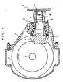
- Fig. 7 is a sectional view of a differential device having a bearing device for supporting a pinion shaft adopted therein.
- Fig. 8 is a partial sectional view of a bearing device for supporting a pinion shaft.
- a differential case 1 is a differential case, and in the differential case 1 are housed a differential speed change mechanism 2 for differentially gearing right and left wheels, a pinion gear 3, a pinion shaft 4, first and second tilt-contact rolling bearings 5 and 6 for supporting the pinion shaft 4 so as to freely rotate, and the like.
- the pinion gear 3 is engaged with a ring gear 2a of the differential speed change mechanism 2 and is formed integral with the inner end portion of the pinion shaft 4.
- the pinion shaft 4 is supported by the first and second tilt-contact rolling bearings 5 and 6 arranged axially in parallel so as to freely rotate with respect to the differential case 1 and is provided with, at the outer end portion thereof, a companion flange 7 serving as a connecting flange, with which a propeller shaft (not shown) is coupled.
- the first tilt-contact rolling bearing 5 on the companion flange side is formed from a single row angular ball bearing 51.
- the pinion-gear-side second tilt-contact rolling bearing 6 is formed from double row angular ball bearings 61 and 62.
- the lines of action of the angular ball bearing 51 of the first tilt-contact rolling bearing 5 and the angular ball bearings 61 and 62 of the second tilt-contact rolling bearing 6 intersect with one another on an outer ring side, and the first and second tilt-contact rolling bearings 5 and 6 form the rolling bearing of rear-surface-coupling type.
- the angular ball bearing 51 is comprised of an inner ring 52, an outer ring 53, and a group of balls 54 retained by a retainer 55, and the companion-flange-side end portions of the inner ring 52 and outer ring 53 are sealed with a seal member 71.
- the angular ball bearings 61 and 62 are respectively comprised of inner rings 63 and 64, outer rings 65 and 66 and groups of balls 67 and 68 retained by retainers 69 and 70.
- the pinion-gear-side end portions of the inner ring 63 and outer ring 65 are sealed with a seal member 72.
- the angular ball bearings 61 and 62 forming the second tilt-contact rolling bearing 6 are provided in parallel and fitted outward to the pinion shaft 4.
- the pinion shaft 4 is inserted from the large-diameter-side opening portion of a bearing case portion 1a so that the outer rings 65 and 66 are fixedly pressure-fitted to an annular wall 1b.
- the first tilt-contact rolling bearing 5 is fitted outward to the pinion shaft 4 from a drive shaft side via a spacer 8 provided between itself and the second tilt-contact rolling bearing 6, and the outer ring 53 is fixedly pressure-fitted to an annular wall 1c.
- a grease G infills between the seal members 71 and 72 on both of the axial ends, that is a sealed space between the respective inner and outer rings of the first and second tilt-contact rolling bearings 5 and 6 and a sealed space between the bearing case portion 1a and the pinion shaft 4 and between the first and second tilt-contact rolling bearings 5 and 6.
- the companion flange 7 is spline-fitted to a drive-shaft-side small diameter portion 42 of the pinion shaft 4, and a nut 15 is fastened into the companion flange 7.
- the first and second tilt-contact rolling bearings 5 and 6 disposed in parallel via the spacer 8 are sandwiched between the pinion gear 3 and the companion flange 7, and thereby preloaded and fixed to the pinion shaft 4.
- the seal member 71 is formed in the manner similar to the seal member 37 shown in Fig. 3A.
- the seal member 72 is formed in the manner similar to the seal member 38 shown in Fig. 3B.
- the grease exemplified in the embodiment of the present invention describing Figs. 1 through 3, or the like, is used as the grease G.
- the pinion shaft 4 subject to axial and radial loads by the first and second tilt-contact rolling bearings 5 and 6, is supported so as to freely rotate with respect to the differential case 1.
- the angular ball bearings 61 and 62 of small frictional resistance are used for the second tilt-contact rolling bearing 6 which a large thrust load acts on, wherein a running torque is reduced compared to the case of a tapered roller bearing resulting in an improved efficiency of the differential device.
- the running torque is further reduced by the angular ball bearing 51 of small frictional resistance used for the first tilt-contact rolling bearing 5.
- the load capacity is increased because of the double row angular ball bearings 61 and 62 used for the second tilt-contact rolling bearing 6 which a large thrust load acts on.
- a sufficient supporting rigidity is successfully obtained despite the ball bearing.
- the bearing device for supporting a pinion shaft requires grease for lubrication, which suppresses the increase of the torque due to resistance caused by agitated oil; it is unnecessary to provide oil introducing and oil reflux paths in the differential case 1, which reduces the differential case 1 in size and weight; and the bearing device is free of any impact from foreign matter in oil in the differential case 1 because of grease lubrication. The life of the bearing device is therefore improved, and no maintenance is required.
- a sealed space which is infilled with the grease G, is formed not only between the respective inner and outer rings of the first and second tilt-contact rolling bearings 5 and 6 but also between the bearing case 1a and the pinion shaft 4 and the first and second tilt-contact rolling bearings 5 and 6.
- a sufficient amount of the grease G is contained to lubricate the bearing.
- a single row angular ball bearing may be used for the second tilt-contact bearing 6.
- FIG. 9 shows a partial sectional view of a bearing device for supporting a pinion shaft adopted in a differential device.
- a bearing device for supporting a pinion shaft adopted in a differential device For any part identical to those in Figs. 7 and 8, the same reference numerals are shown to omit explanations.
- a tandem double row angular ball bearing is used for a second tilt-contact rolling bearing 6.
- the second tilt-contact rolling bearing 6 is comprised of an inner ring 80, an outer ring 81, groups of balls 67 and 68 arranged in two rows and retained by retainers 69 and 70, wherein a space between the pinion-gear-side end portions of the inner ring 80 and outer ring 81 is sealed with a seal member 72.
- the pinion-gear-side group of balls 67 are disposed radially outward relative to the other group of balls 68 and formed in tandem structure.
- the double row angular ball bearing of small frictional resistance is used for the second tilt-contact rolling bearing 6, and a running torque is thereby reduced to consequently improve the efficiency of the differential device.
- grease is used for lubrication to thereby suppress the increase of the torque caused by resistance due to agitated oil.
- the differential device is reduced in size and weight to consequently improving the life of the bearing, and no maintenance is necessary.
- the tandem double row angular ball bearing is used for the second tilt-contact rolling bearing 6, the number of the pinion-gear-side group of balls 67 is increased, and a load capacity thereby becomes larger. Accordingly, a sufficient load capacity is obtained despite a smaller running torque, which improves the efficiency of the differential device.
- Fig. 10 is a partial sectional view of a modification example of the bearing device for supporting a pinion according to this embodiment.
- a tandem double row angular ball bearing is used for a first tilt-contact rolling bearing 5.
- the first tilt-contact rolling bearing 5 is comprised of an inner ring 52, an outer ring 53, and groups of balls 56 and 57 arranged in two rows and retained by retainers 58 and 59, wherein a space between the companion-flange-side end portions of the inner ring 52 and outer ring 53 is sealed with a seal member 71.
- the companion-flange-side group of balls 56 are disposed radially outward relative to the other group of balls 57 and formed in tandem structure.
- Fig. 11 is a partial sectional view of another modification example of the bearing device for supporting a pinion shaft of this embodiment.
- a single row tapered roller bearing is used for a first tilt-contact rolling bearing 5.
- the first tilt-contact rolling bearing 5 is comprised of an inner ring 52, an outer ring 53, a group of tapered rollers 54 and a retainer 55.
- tapered roller bearing is used for the first tilt-contact, rolling bearing 5 as described, a preload is set more easily compared to the case of a ball bearing.
- the bearing device for supporting a pinion shaft according to the present invention is suitable for supporting a pinion shaft which is installed in a differential device of an automobile, a four-wheel-drive transfer device, or the like, so as to freely rotate.
Landscapes
- Engineering & Computer Science (AREA)
- General Engineering & Computer Science (AREA)
- Mechanical Engineering (AREA)
- Rolling Contact Bearings (AREA)
Abstract
Description
Claims (8)
- A bearing device for supporting a pinion shaft having a pinion gear on one end side thereof and a connecting flange on another end thereof so as to freely rotate with respect to a case, comprising:afirst tilt-contact rolling bearing provided on an outer peripheral surface of the pinion shaft on the connecting flange side thereof; anda second tilt-contact rolling bearing formed from an angular ball bearing provided on an outer peripheral surface of the pinion shaft on the pinion gear side thereof, whereinlines of action of the first and second tilt-contact rolling bearings intersect with one another on an outer diameter side,a connecting-flange-side and portion of the first tilt-contact rolling bearing and a pinion-gear-side end portion of the second tilt-contact rolling bearing are respectively sealed with seal members, and a sealed space between the seal members is infilled with grease, andthe connecting flange is fastened in the pinion-gear direction to thereby preload the first and second tilt-contact rolling bearings.
- A bearing device for supporting a pinion shaft having a pinion gear on one end side thereof and a connecting flange on another end thereof so as to freely rotate with respect to a case, comprising:a first tilt-contact rolling bearing provided on an outer peripheral surface of the pinion shaft on the connecting flange side thereof; anda second tilt-contact rolling bearing provided on an outer peripheral surface of the pinion shaft on the pinion gear side thereof, whereinlines of action of the first and second tilt-contact rolling bearings intersect with one another on an outer diameter side,the first tilt-contact rolling bearing is comprised of an inner ring fixed to the pinion shaft, an outer ring fixed to the case, rolling bodies interposed between the inner and outer rings, and a seal member sealing a connecting-flange-side end portion between the inner and outer rings,the second tilt-contact rolling bearing constitutes an angular ball bearing formed from an inner ring fixed to the pinion shaft, an outer ring fixed to the case, a group of balls interposed between the inner and outer rings, and a seal member sealing a pinion-gear-aide end portion between the inner and outer rings,the outer rings of the first and second tilt-contact rolling bearings are made up into a unit so that the first and second tilt-contact rolling bearings form a bearing unit, anda sealed space between the seal members is infilled with grease, and the connecting flange is fastened in the pinion-gear direction to thereby preload the bearing unit.
- The bearing device for supporting a pinion shaft as claimed in Claim 2, wherein
the inner ring of the first tilt-contact rolling bearing is formed integral with the connecting flange. - The bearing device for supporting a pinion shaft as claimed in Claim 2, wherein
the inner ring of the second tilt-contact rolling bearing is formed integral with the pinion shaft. - The bearing device for supporting a pinion shaft as claimed in Claim 2, wherein
the second tilt-contact rolling bearing constitutes a tandem double row angular ball bearing having a pinion-gear-side group of balls disposed closer to an outer diameter. - A bearing device for supporting a pinion shaft having a pinion gear on one end side thereof and a connecting flange on another end thereof so as to freely rotate with respect to a case, comprising:a first tilt-contact rolling bearing provided on an outer peripheral surface of the pinion shaft on the connecting flange side thereof; anda second tilt-contact rolling bearing provided on an outer peripheral surface of the pinion shaft on the pinion gear side thereof, whereinlines of action of the first and second tilt-contact rolling bearings intersect with one another on an outer diameter side,the first tilt-contact rolling bearing is comprised of an inner ring fixed to the pinion shaft, an outer ring fixed to the case, rolling bodies interposed between the inner and outer rings, and a seal member sealing a connecting-flange-side end portion between the inner and outer rings,the second tilt-contact rolling bearing constitutes an angular ball bearing formed from an inner ring fixed to the pinion shaft, an outer ring fixed to the case, a group of balls interposed between the inner and outer rings, and a seal member sealing a pinion-gear-side end portion between the inner and outer rings,a sealed space between the seal members is infilled with grease, andthe connecting flange is fastened in the pinion-gear direction to thereby preload the first and second tilt-contact rolling bearings.
- The bearing device for supporting a pinion shaft as claimed in Claim 6, wherein
a spacer is interposed between the inner rings of the first and second tilt-contact rolling bearings. - The bearing device for supporting a pinion shaft as claimed in Claim 6, wherein
the second tilt-contact rolling bearing constitutes a tandem double row angular ball bearing having a pinion-gear-side group of balls disposed closer to an outer diameter.
Applications Claiming Priority (7)
| Application Number | Priority Date | Filing Date | Title |
|---|---|---|---|
| JP2001343157A JP4223209B2 (en) | 2001-11-08 | 2001-11-08 | Pinion shaft support bearing unit |
| JP2001343157 | 2001-11-08 | ||
| JP2001343156A JP2003148459A (en) | 2001-11-08 | 2001-11-08 | Bearing device for supporting pinion shaft |
| JP2001343156 | 2001-11-08 | ||
| JP2001369911 | 2001-12-04 | ||
| JP2001369911 | 2001-12-04 | ||
| PCT/JP2002/011656 WO2003040578A1 (en) | 2001-11-08 | 2002-11-08 | Bearing device for supporting pinion shaft |
Publications (3)
| Publication Number | Publication Date |
|---|---|
| EP1443228A1 true EP1443228A1 (en) | 2004-08-04 |
| EP1443228A4 EP1443228A4 (en) | 2010-05-12 |
| EP1443228B1 EP1443228B1 (en) | 2011-03-30 |
Family
ID=27347800
Family Applications (1)
| Application Number | Title | Priority Date | Filing Date |
|---|---|---|---|
| EP02778068A Expired - Lifetime EP1443228B1 (en) | 2001-11-08 | 2002-11-08 | Bearing device for supporting pinion shaft |
Country Status (4)
| Country | Link |
|---|---|
| US (1) | US7287911B2 (en) |
| EP (1) | EP1443228B1 (en) |
| DE (1) | DE60239630D1 (en) |
| WO (1) | WO2003040578A1 (en) |
Cited By (17)
| Publication number | Priority date | Publication date | Assignee | Title |
|---|---|---|---|---|
| DE102004020851A1 (en) * | 2004-04-28 | 2005-11-24 | Ina-Schaeffler Kg | Bearing arrangement for shaft in particular of transmission unit of vehicle, comprising two differently designed twin bearings |
| WO2005110032A3 (en) * | 2004-05-07 | 2006-02-02 | Timken Co | Locating bearing assembly for wind turbine gearbox shaft |
| WO2006018132A1 (en) * | 2004-08-10 | 2006-02-23 | Schaeffler Kg | Multi-row angular ball bearing |
| DE102005004184A1 (en) * | 2004-08-31 | 2006-03-02 | Ina-Schaeffler Kg | Bearing unit, e.g. for downward drilling motors, has bearing holders with conical running tracks and axes of symmetry that are inclined with respect to main axis of at least one inner ring and/or first outer ring |
| DE102005041917A1 (en) * | 2005-09-03 | 2007-03-08 | Schaeffler Kg | Tandem angular contact ball bearings |
| DE102006004297A1 (en) * | 2006-01-31 | 2007-08-02 | Schaeffler Kg | Asymmetrical three-row rolling bearing |
| DE102006004274A1 (en) * | 2006-01-31 | 2007-08-02 | Schaeffler Kg | Multi-row rolling bearing |
| DE102006031956A1 (en) * | 2006-07-11 | 2008-01-17 | Schaeffler Kg | Double-row ball bearing for motor vehicle, has rows of bearing balls rolling between inner and outer rings, where row of balls are assigned to four-point-ball bearing and angular ball bearing, and inner ring is divided into path areas |
| EP1840391A3 (en) * | 2006-03-29 | 2008-06-04 | JTEKT Corporation | Rolling bearing device with a double row rolling contact bearing for supporting a pinion shaft |
| DE102006060678A1 (en) * | 2006-12-21 | 2008-06-26 | Schaeffler Kg | Storage arrangement of a shaft |
| DE102007009918A1 (en) * | 2007-02-27 | 2008-09-04 | Ab Skf | Wheel bearing for bearing of wheels rotating around axis of rotation, has tapered roller bearing with tapered-roller row and inclined ball bearing with two ball races |
| DE102007061017A1 (en) | 2007-12-18 | 2009-06-25 | Schaeffler Kg | Bearing arrangement for mounting a pinion shaft |
| DE102011087427B3 (en) * | 2011-11-30 | 2013-05-29 | Aktiebolaget Skf | Machine assembly e.g. gearbox assembly has connection section extended in axial direction, which is mounted at sealing element with respect to annular groove-shaped trepan |
| US9151329B2 (en) | 2013-07-03 | 2015-10-06 | Aktiebolaget Skf | Machine assembly |
| DE102015221407A1 (en) * | 2015-11-02 | 2016-12-22 | Schaeffler Technologies AG & Co. KG | Bearing arrangement for a pinion shaft |
| KR20190000152A (en) * | 2017-06-22 | 2019-01-02 | 주식회사 베어링아트 | Double row bearing for pinion shaft and differential device comprising the same |
| DE102017125910A1 (en) * | 2017-11-07 | 2019-05-09 | Schaeffler Technologies AG & Co. KG | Three-row angular contact ball bearing |
Families Citing this family (22)
| Publication number | Priority date | Publication date | Assignee | Title |
|---|---|---|---|---|
| WO2005065077A2 (en) * | 2003-10-14 | 2005-07-21 | Ab Skf | Asymmetric hub assembly |
| JP2007205429A (en) * | 2006-01-31 | 2007-08-16 | Jtekt Corp | Pinion shaft ball bearings |
| US8136996B2 (en) * | 2008-02-25 | 2012-03-20 | Hamilton Sundstrand Corporation | Frustoconical ball bearing and preloaded ball bearing assemblies |
| DE102008030792A1 (en) * | 2008-04-22 | 2009-10-29 | Schaeffler Kg | Angular contact ball bearings for supporting a gear shaft arrangement |
| US20110222807A1 (en) * | 2009-11-20 | 2011-09-15 | Yasushi Tanoue | Tandem angular ball bearing |
| DE102010013627A1 (en) * | 2010-04-01 | 2011-10-06 | Aktiebolaget Skf | Bearing arrangement and gearbox |
| US9562593B2 (en) * | 2011-06-13 | 2017-02-07 | Ntn Corporation | Chain guide and chain drive apparatus |
| JP5706261B2 (en) * | 2011-07-25 | 2015-04-22 | Ntn株式会社 | Chain transmission for camshaft drive |
| WO2013136956A1 (en) * | 2012-03-12 | 2013-09-19 | Ntn株式会社 | Chain guide and chain drive device |
| EP2857718B1 (en) * | 2012-05-24 | 2017-01-04 | NTN Corporation | Chain guide and chain transmission device |
| US9593756B2 (en) | 2013-07-31 | 2017-03-14 | American Axle & Manufacturing, Inc. | Bearing assembly configured to handle axial and radial loads |
| US9347493B2 (en) * | 2013-10-21 | 2016-05-24 | Schaeffler Technologies AG & Co. KG | Bearing assembly including tapered rollers and spherical rolling elements |
| JP6205291B2 (en) * | 2014-02-17 | 2017-09-27 | Ntn株式会社 | Chain drive for camshaft drive |
| EP3001051A1 (en) * | 2014-09-29 | 2016-03-30 | Aktiebolaget SKF | Bearing unit for pinions |
| US10508727B2 (en) * | 2016-08-31 | 2019-12-17 | Spx Flow, Inc. | Drive system and drive sub-assembly for driving a shaft |
| CA3147115A1 (en) * | 2019-07-12 | 2021-01-21 | Linamar Corporation | Differential with a plastic deflector having a stainless steel running surface |
| DE102020204202A1 (en) | 2020-03-31 | 2021-09-30 | Zf Friedrichshafen Ag | Universal drive housing |
| US11225107B1 (en) | 2020-09-09 | 2022-01-18 | Mahindra N.A. Tech Center | Axle carrier housing with reinforcement structure |
| US11535057B2 (en) | 2020-09-09 | 2022-12-27 | Mahindra N.A. Tech Center | Axle assembly with sealed wheel end bearings and sealed pinion input bearings |
| US11648745B2 (en) | 2020-09-09 | 2023-05-16 | Mahindra N.A. Tech Center | Modular tooling for axle housing and manufacturing process |
| US11655891B2 (en) | 2020-09-09 | 2023-05-23 | Mahindra N.A. Tech Center | Method of machining an axle carrier housing |
| US11193573B1 (en) | 2020-09-18 | 2021-12-07 | Schaeffler Technologies AG & Co. KG | Differential pinion bearing assembly |
Family Cites Families (6)
| Publication number | Priority date | Publication date | Assignee | Title |
|---|---|---|---|---|
| US3792625A (en) * | 1971-06-28 | 1974-02-19 | Skf Ind Trading & Dev | Pinion gear transmission |
| JPS53109049A (en) * | 1977-03-03 | 1978-09-22 | Nippon Seiko Kk | Gear power transmission shaft holder |
| US5492419A (en) * | 1994-07-19 | 1996-02-20 | Ntn Corporation | Cartridge axle pinion bearing assembly |
| JPH109259A (en) * | 1996-06-26 | 1998-01-13 | Nippon Seiko Kk | Bearing unit for supporting pinion shaft of differential gear |
| JP2000002239A (en) | 1998-06-16 | 2000-01-07 | Tochigi Fuji Ind Co Ltd | Thrust bearing mechanism |
| DE19839481C2 (en) * | 1998-08-29 | 2003-06-05 | Ina Schaeffler Kg | Transfer case for a motor vehicle |
-
2002
- 2002-11-08 EP EP02778068A patent/EP1443228B1/en not_active Expired - Lifetime
- 2002-11-08 US US10/494,152 patent/US7287911B2/en not_active Expired - Fee Related
- 2002-11-08 WO PCT/JP2002/011656 patent/WO2003040578A1/en not_active Ceased
- 2002-11-08 DE DE60239630T patent/DE60239630D1/en not_active Expired - Lifetime
Cited By (30)
| Publication number | Priority date | Publication date | Assignee | Title |
|---|---|---|---|---|
| DE102004020851A1 (en) * | 2004-04-28 | 2005-11-24 | Ina-Schaeffler Kg | Bearing arrangement for shaft in particular of transmission unit of vehicle, comprising two differently designed twin bearings |
| DE102004020851B4 (en) * | 2004-04-28 | 2013-12-24 | Schaeffler Technologies AG & Co. KG | Storage of a shaft |
| WO2005110032A3 (en) * | 2004-05-07 | 2006-02-02 | Timken Co | Locating bearing assembly for wind turbine gearbox shaft |
| US7572061B2 (en) | 2004-05-07 | 2009-08-11 | The Timken Company | Locating bearing assembly for wind turbine gearbox shaft |
| WO2006018132A1 (en) * | 2004-08-10 | 2006-02-23 | Schaeffler Kg | Multi-row angular ball bearing |
| DE102004038709A1 (en) * | 2004-08-10 | 2006-02-23 | Ina-Schaeffler Kg | Multi-row angular contact ball bearings |
| DE102005004184A1 (en) * | 2004-08-31 | 2006-03-02 | Ina-Schaeffler Kg | Bearing unit, e.g. for downward drilling motors, has bearing holders with conical running tracks and axes of symmetry that are inclined with respect to main axis of at least one inner ring and/or first outer ring |
| DE102005041917A1 (en) * | 2005-09-03 | 2007-03-08 | Schaeffler Kg | Tandem angular contact ball bearings |
| WO2007087775A1 (en) * | 2006-01-31 | 2007-08-09 | Schaeffler Kg | Asymmetrical triple-row anti-friction bearing |
| DE102006004297B4 (en) * | 2006-01-31 | 2019-03-07 | Schaeffler Kg | Asymmetrical three-row rolling bearing |
| DE102006004274A1 (en) * | 2006-01-31 | 2007-08-02 | Schaeffler Kg | Multi-row rolling bearing |
| DE102006004297A1 (en) * | 2006-01-31 | 2007-08-02 | Schaeffler Kg | Asymmetrical three-row rolling bearing |
| US8007182B2 (en) | 2006-01-31 | 2011-08-30 | Schaeffler Kg | Asymmetrical triple-row anti-friction bearing |
| RU2429392C2 (en) * | 2006-01-31 | 2011-09-20 | Шеффлер Текнолоджиз Гмбх Унд Ко.Кг | Three-row asymmetrical rolling bearing and bearing unit of wheel hub with said rolling bearing |
| CN101400905B (en) * | 2006-01-31 | 2012-02-08 | 谢夫勒两合公司 | Roller bearing as wheel bearing and wheel support |
| EP1840391A3 (en) * | 2006-03-29 | 2008-06-04 | JTEKT Corporation | Rolling bearing device with a double row rolling contact bearing for supporting a pinion shaft |
| US7811000B2 (en) | 2006-03-29 | 2010-10-12 | Jtekt Corporation | Rolling bearing device for supporting pinion shaft |
| DE102006031956A1 (en) * | 2006-07-11 | 2008-01-17 | Schaeffler Kg | Double-row ball bearing for motor vehicle, has rows of bearing balls rolling between inner and outer rings, where row of balls are assigned to four-point-ball bearing and angular ball bearing, and inner ring is divided into path areas |
| DE102006060678A1 (en) * | 2006-12-21 | 2008-06-26 | Schaeffler Kg | Storage arrangement of a shaft |
| DE102007009918A1 (en) * | 2007-02-27 | 2008-09-04 | Ab Skf | Wheel bearing for bearing of wheels rotating around axis of rotation, has tapered roller bearing with tapered-roller row and inclined ball bearing with two ball races |
| WO2009077253A1 (en) * | 2007-12-18 | 2009-06-25 | Schaeffler Kg | Bearing arrangement for supporting a pinion shaft |
| DE102007061017B4 (en) * | 2007-12-18 | 2012-08-16 | Schaeffler Technologies Gmbh & Co. Kg | Bearing arrangement for mounting a pinion shaft |
| DE102007061017A1 (en) | 2007-12-18 | 2009-06-25 | Schaeffler Kg | Bearing arrangement for mounting a pinion shaft |
| DE102011087427B3 (en) * | 2011-11-30 | 2013-05-29 | Aktiebolaget Skf | Machine assembly e.g. gearbox assembly has connection section extended in axial direction, which is mounted at sealing element with respect to annular groove-shaped trepan |
| US9151329B2 (en) | 2013-07-03 | 2015-10-06 | Aktiebolaget Skf | Machine assembly |
| DE102013212989B4 (en) * | 2013-07-03 | 2015-10-08 | Aktiebolaget Skf | engine assembly |
| DE102015221407A1 (en) * | 2015-11-02 | 2016-12-22 | Schaeffler Technologies AG & Co. KG | Bearing arrangement for a pinion shaft |
| KR20190000152A (en) * | 2017-06-22 | 2019-01-02 | 주식회사 베어링아트 | Double row bearing for pinion shaft and differential device comprising the same |
| DE102017125910A1 (en) * | 2017-11-07 | 2019-05-09 | Schaeffler Technologies AG & Co. KG | Three-row angular contact ball bearing |
| DE102017125910B4 (en) * | 2017-11-07 | 2019-05-23 | Schaeffler Technologies AG & Co. KG | Three-row angular contact ball bearing |
Also Published As
| Publication number | Publication date |
|---|---|
| DE60239630D1 (en) | 2011-05-12 |
| US7287911B2 (en) | 2007-10-30 |
| US20050031240A1 (en) | 2005-02-10 |
| EP1443228B1 (en) | 2011-03-30 |
| WO2003040578A1 (en) | 2003-05-15 |
| EP1443228A4 (en) | 2010-05-12 |
Similar Documents
| Publication | Publication Date | Title |
|---|---|---|
| EP1443228B1 (en) | Bearing device for supporting pinion shaft | |
| EP1498621B1 (en) | Pinion shaft with supporting bearing device therefor | |
| US8777492B2 (en) | Wheel bearing apparatus | |
| JP4557223B2 (en) | Drive wheel bearing device | |
| JP2003166627A (en) | Pinion shaft supporting bearing device | |
| EP1693580A1 (en) | Bearing device for supporting pinion shaft and pinion shaft supporting device | |
| EP1693581B1 (en) | Bearing device for supporting pinion shaft | |
| JP2006298225A (en) | Drive wheel bearing device | |
| JP2016130113A (en) | Semi-floating type wheel support device | |
| US7690449B2 (en) | Output yoke shaft and assembly | |
| JP2004169890A (en) | Pinion shaft supporting bearing device | |
| JP2003232346A (en) | Bearing device for supporting pinion shaft | |
| JP4069616B2 (en) | Bearing device for pinion shaft support | |
| JP2004183745A (en) | Double-row ball bearing | |
| JP4223209B2 (en) | Pinion shaft support bearing unit | |
| JP2003156128A (en) | Pinion shaft supporting bearing device | |
| JP4333126B2 (en) | Pinion shaft support bearing device | |
| JP4525208B2 (en) | Bearing device for pinion shaft support | |
| KR20210095119A (en) | Steering system with pivot bearings | |
| JP2014025524A (en) | Pinion shaft supporting bearing device | |
| JP2003148459A (en) | Bearing device for supporting pinion shaft | |
| JP2004211861A (en) | Double-row ball bearing | |
| CN114076153A (en) | Wheel bearing assembly and method of installation | |
| JP4348955B2 (en) | Differential | |
| JP2006029520A (en) | Tapered roller bearing |
Legal Events
| Date | Code | Title | Description |
|---|---|---|---|
| PUAI | Public reference made under article 153(3) epc to a published international application that has entered the european phase |
Free format text: ORIGINAL CODE: 0009012 |
|
| 17P | Request for examination filed |
Effective date: 20040521 |
|
| AK | Designated contracting states |
Kind code of ref document: A1 Designated state(s): AT BE BG CH CY CZ DE DK EE ES FI FR GB GR IE IT LI LU MC NL PT SE SK TR |
|
| RAP1 | Party data changed (applicant data changed or rights of an application transferred) |
Owner name: JTEKT CORPORATION |
|
| A4 | Supplementary search report drawn up and despatched |
Effective date: 20100412 |
|
| GRAP | Despatch of communication of intention to grant a patent |
Free format text: ORIGINAL CODE: EPIDOSNIGR1 |
|
| RIC1 | Information provided on ipc code assigned before grant |
Ipc: F16H 57/02 20060101ALI20101020BHEP Ipc: F16C 19/54 20060101ALI20101020BHEP Ipc: F16C 19/18 20060101AFI20101020BHEP Ipc: F16C 25/06 20060101ALI20101020BHEP Ipc: F16C 33/66 20060101ALI20101020BHEP Ipc: F16H 48/08 20060101ALI20101020BHEP |
|
| GRAS | Grant fee paid |
Free format text: ORIGINAL CODE: EPIDOSNIGR3 |
|
| GRAA | (expected) grant |
Free format text: ORIGINAL CODE: 0009210 |
|
| AK | Designated contracting states |
Kind code of ref document: B1 Designated state(s): DE FR GB |
|
| REG | Reference to a national code |
Ref country code: GB Ref legal event code: FG4D |
|
| REF | Corresponds to: |
Ref document number: 60239630 Country of ref document: DE Date of ref document: 20110512 Kind code of ref document: P |
|
| REG | Reference to a national code |
Ref country code: DE Ref legal event code: R096 Ref document number: 60239630 Country of ref document: DE Effective date: 20110512 |
|
| PLBE | No opposition filed within time limit |
Free format text: ORIGINAL CODE: 0009261 |
|
| STAA | Information on the status of an ep patent application or granted ep patent |
Free format text: STATUS: NO OPPOSITION FILED WITHIN TIME LIMIT |
|
| 26N | No opposition filed |
Effective date: 20120102 |
|
| REG | Reference to a national code |
Ref country code: DE Ref legal event code: R097 Ref document number: 60239630 Country of ref document: DE Effective date: 20120102 |
|
| GBPC | Gb: european patent ceased through non-payment of renewal fee |
Effective date: 20111108 |
|
| PG25 | Lapsed in a contracting state [announced via postgrant information from national office to epo] |
Ref country code: GB Free format text: LAPSE BECAUSE OF NON-PAYMENT OF DUE FEES Effective date: 20111108 |
|
| REG | Reference to a national code |
Ref country code: FR Ref legal event code: PLFP Year of fee payment: 14 |
|
| PGFP | Annual fee paid to national office [announced via postgrant information from national office to epo] |
Ref country code: FR Payment date: 20151008 Year of fee payment: 14 |
|
| PGFP | Annual fee paid to national office [announced via postgrant information from national office to epo] |
Ref country code: DE Payment date: 20161101 Year of fee payment: 15 |
|
| REG | Reference to a national code |
Ref country code: FR Ref legal event code: ST Effective date: 20170731 |
|
| PG25 | Lapsed in a contracting state [announced via postgrant information from national office to epo] |
Ref country code: FR Free format text: LAPSE BECAUSE OF NON-PAYMENT OF DUE FEES Effective date: 20161130 |
|
| REG | Reference to a national code |
Ref country code: DE Ref legal event code: R119 Ref document number: 60239630 Country of ref document: DE |
|
| PG25 | Lapsed in a contracting state [announced via postgrant information from national office to epo] |
Ref country code: DE Free format text: LAPSE BECAUSE OF NON-PAYMENT OF DUE FEES Effective date: 20180602 |