EP1443179A2 - A rotor and a retaining plate for the same - Google Patents
A rotor and a retaining plate for the same Download PDFInfo
- Publication number
- EP1443179A2 EP1443179A2 EP04250077A EP04250077A EP1443179A2 EP 1443179 A2 EP1443179 A2 EP 1443179A2 EP 04250077 A EP04250077 A EP 04250077A EP 04250077 A EP04250077 A EP 04250077A EP 1443179 A2 EP1443179 A2 EP 1443179A2
- Authority
- EP
- European Patent Office
- Prior art keywords
- disc
- rotor
- retaining plate
- channel
- outer edge
- Prior art date
- Legal status (The legal status is an assumption and is not a legal conclusion. Google has not performed a legal analysis and makes no representation as to the accuracy of the status listed.)
- Granted
Links
- 238000007373 indentation Methods 0.000 claims abstract description 10
- 230000001141 propulsive effect Effects 0.000 description 6
- 230000001154 acute effect Effects 0.000 description 2
- 238000003780 insertion Methods 0.000 description 2
- 230000037431 insertion Effects 0.000 description 2
- 230000002411 adverse Effects 0.000 description 1
- 238000002485 combustion reaction Methods 0.000 description 1
- 230000006835 compression Effects 0.000 description 1
- 238000007906 compression Methods 0.000 description 1
- 239000000446 fuel Substances 0.000 description 1
- 239000000203 mixture Substances 0.000 description 1
- 238000012986 modification Methods 0.000 description 1
- 230000004048 modification Effects 0.000 description 1
Images

Classifications
-
- F—MECHANICAL ENGINEERING; LIGHTING; HEATING; WEAPONS; BLASTING
- F01—MACHINES OR ENGINES IN GENERAL; ENGINE PLANTS IN GENERAL; STEAM ENGINES
- F01D—NON-POSITIVE DISPLACEMENT MACHINES OR ENGINES, e.g. STEAM TURBINES
- F01D5/00—Blades; Blade-carrying members; Heating, heat-insulating, cooling or antivibration means on the blades or the members
- F01D5/30—Fixing blades to rotors; Blade roots ; Blade spacers
- F01D5/3007—Fixing blades to rotors; Blade roots ; Blade spacers of axial insertion type
- F01D5/3015—Fixing blades to rotors; Blade roots ; Blade spacers of axial insertion type with side plates
-
- F—MECHANICAL ENGINEERING; LIGHTING; HEATING; WEAPONS; BLASTING
- F05—INDEXING SCHEMES RELATING TO ENGINES OR PUMPS IN VARIOUS SUBCLASSES OF CLASSES F01-F04
- F05D—INDEXING SCHEME FOR ASPECTS RELATING TO NON-POSITIVE-DISPLACEMENT MACHINES OR ENGINES, GAS-TURBINES OR JET-PROPULSION PLANTS
- F05D2250/00—Geometry
- F05D2250/30—Arrangement of components
- F05D2250/31—Arrangement of components according to the direction of their main axis or their axis of rotation
- F05D2250/314—Arrangement of components according to the direction of their main axis or their axis of rotation the axes being inclined in relation to each other
-
- F—MECHANICAL ENGINEERING; LIGHTING; HEATING; WEAPONS; BLASTING
- F05—INDEXING SCHEMES RELATING TO ENGINES OR PUMPS IN VARIOUS SUBCLASSES OF CLASSES F01-F04
- F05D—INDEXING SCHEME FOR ASPECTS RELATING TO NON-POSITIVE-DISPLACEMENT MACHINES OR ENGINES, GAS-TURBINES OR JET-PROPULSION PLANTS
- F05D2260/00—Function
- F05D2260/30—Retaining components in desired mutual position
-
- Y—GENERAL TAGGING OF NEW TECHNOLOGICAL DEVELOPMENTS; GENERAL TAGGING OF CROSS-SECTIONAL TECHNOLOGIES SPANNING OVER SEVERAL SECTIONS OF THE IPC; TECHNICAL SUBJECTS COVERED BY FORMER USPC CROSS-REFERENCE ART COLLECTIONS [XRACs] AND DIGESTS
- Y02—TECHNOLOGIES OR APPLICATIONS FOR MITIGATION OR ADAPTATION AGAINST CLIMATE CHANGE
- Y02T—CLIMATE CHANGE MITIGATION TECHNOLOGIES RELATED TO TRANSPORTATION
- Y02T50/00—Aeronautics or air transport
- Y02T50/60—Efficient propulsion technologies, e.g. for aircraft
Definitions
- Embodiments of the present invention relate to a rotor. In particular, they relate to rotors within a gas turbine engine.
- Some parts of a gas turbine engine are highly stressed during operation of the engine. Those parts are engineered to withstand that stress. This often means those parts must be made more substantial to withstand the stress. This may result in an overall increase in engine weight and a decrease in engine efficiency. In addition, a heavily stressed part may have a reduced useful life which also reduces engine efficiency.
- gas turbine engines comprise a number of rotors.
- a rotor may be assembled by slotting rotor blades into slots of a supporting disc connected to a shaft. Posts of the supporting disc prevent radial movement of the rotor blades.
- the rotor blades and the posts of the supporting disc in combination create a channel into which a retaining plate is inserted.
- the retaining plate prevents axial movement of the rotor blades.
- the inventors have recognised that when the engine is in use the centrifugal force on the retaining plate pushes it into the posts of the supporting disc. This increases the stress within the posts, particularly at the acute angle formed when off-axis slots are used.
- the inventors have devised a way of reducing such stress without significantly adding to the complexity of the component parts or the assembly of the engine.
- a retaining plate for a rotor has a radially outer edge, the radially outer edge having at least one indentation.
- a rotor comprises a disc having an axis about which it is able to rotate, the disc supporting a plurality of radially extending blades in slots therein, a channel being defined by the disc and at least one blade, the or each blade and the disc being contiguous in the channel at first and second distinct parts of the disc, and the rotor further comprises at least one retaining plate as described in the preceding paragraph.
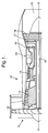
- Fig. 1 illustrates a sectional side view of the upper half of a gas turbine engine 10.
- the gas turbine engine comprises, in axial flow series, an air intake 11, a propulsive fan 12, an intermediate pressure compressor 13, a high pressure compressor 14, a combustor 15, a turbine arrangement comprising a high pressure turbine 16, an intermediate pressure turbine 17 and a low pressure turbine 18 and an exhaust nozzle 19.
- the gas turbine engine 10 operates in a conventional manner so that air entering in the intake 11 is accelerated by the propulsive fan 12 which produces two air flows: a first air flow into the intermediate pressure compressor 13 and a second air flow which provides propulsive thrust.
- the intermediate pressure compressor 13 compresses air flow directed into it for delivering that air to the high pressure compressor 14 where further compression takes place.
- the compressed air exhausted from the high pressure compressor 14 is directed into the combustor 15 where it is mixed with fuel and the mixture combusted.
- the resultant hot combustion products then expand and thereby drive the high, intermediate and low pressure turbines 16, 17, 18 before being exhausted through the nozzle 19 to provide additional propulsive thrust.
- the high, intermediate and low pressure turbines 16, 17, 18 respectively drive the high and intermediate pressure compressors 14, 13 and the propulsive fan 12 by suitable interconnecting shafts 20.
- the high, intermediate and low pressure turbines 16, 17, 18 respectively operative at rotational speeds of approximately 12000rpm, 8000rpm and 3300rpm.
- the high, intermediate and low pressure turbines 16, 17, 18, the propulsive fan 12 and the intermediate pressure compressor 13 and the high pressure compressor 14 are each rotors.
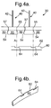
- Figs 2a, 2b, 3a, 3b, 3c, 4a and 4b illustrate the components of a rotor 30 in more detail.
- the rotor 30 comprises a circular supporting disc 50 (illustrated in Figs 3a, 3b, 3c, 4a and 4b); a plurality of rotor blades 40 (one of which is illustrated in Figs 2a, 2b, 4a and 4b) slotted into the supporting disc and a retaining plate 60 (illustrated in Figs 4a and 4b).
- the supporting disc 50 is circular and connected to a shaft for rotation about an axis through the centre of the circle and perpendicular to the plane of the disc.
- the supporting disc 50 supports radially extending rotor blades 40 slotted therein at regular distances around its circumference.
- the supporting disc 50 has a series of circumferentially arranged axially extending slots 52 separated by disc posts 54 for receiving the rotor blades 40.
- Fig 3a, 3b and 3c illustrate a radial extremity of a portion of a supporting disc. In these Figs the radially outer edge of the supporting disc, which is circular, is approximated to a straight line for clarity in the drawings.
- Fig 3a illustrates a sectional side view.
- Fig 3b illustrates an end view.
- Fig 3c illustrates a plan view.
- Each slot 52 extends axially at least part way through the supporting disc, and is skewed at the same angle ⁇ off axis.
- Each disc post 54 therefore has an obtusely angled (90 + ⁇ degrees) portion 57 and an acutely angled (90- ⁇ degrees) portion 55.
- the off-axis angle ⁇ may be as much as 30 degrees.
- Each disc post 54 has a body of width w with a rear retaining hook 56 at one axial extremity, that has the same width w and depends radially part-way towards the axis of the supporting disc 50.
- a channel 58 is formed between the rear retaining hook 56 and the body of the disc post.
- Each slot 52 has an enlarged interior portion 53a and a constricted opening 53b.
- Fig 2a illustrates a sectional side view of a rotor blade 40
- Fig 2b illustrates an end view of the rotor blade 40
- Each rotor blade 40 comprises an aerofoil 42 and a root portion 44 from which the aerofoil 42 extends.
- the root portion 44 has a cross-section substantially similar, but smaller, to the cross-section of the slots 52.
- the root portion 44 has a dovetail 43a at its base and a smaller platform 43b where the aerofoil joins.
- an aerofoil 42 can be slotted by axial movement into the slot 52.
- the disc posts 54 on either side of the slot 52 define the constricted opening 53b of the slot 52 and prevent the movement of the rotor blade 40 in a radial direction.
- each rotor blade 40 has a body portion of width W with a rear retaining hook 46, at a radial extremity, that has the same width W and points radially inwards.
- a channel 48 is formed between the rear retaining hook 46 and the body portion of the root portion 44.
- the rotor 30 is assembled by slotting the rotor blades 40 into the slots 52 of the supporting disc 50 as shown in Fig 4a.
- the disc posts 54 of the supporting disc 50 prevent radial movement of the rotor blades 40.
- the rear retaining hooks 46 of the rotor blades 40 and the rear retaining hooks 56 of the supporting disc 50 are aligned.
- the hooks 46, 56 combine to define one side wall of a single channel formed from channels 48, 58.
- the single channel extends lengthwise circumferentially all the way around the axis in the form of a closed circle.
- a disc post 54 is contiguous with the root portion 44 of its adjacent rotor blades 40. Within the single channel, each disc post 54 is contiguous with a first neighbouring root portion 44 at a first portion 55 and is contiguous with a second neighbouring root portion 44 at a second portion 57. The first portion 55 of the disc post 54 is acutely angled. The second portion 57 of the disc post 54 is obtusely angled.
- FIG. 4a illustrates, using an end view, the insertion (in direction A) of a retaining plate 60 into the single channel.
- Fig 4b illustrates a perspective view of a retaining plate.
- the retaining plate 60 has a body with a radially outer edge 62.
- the radially outer edge 62 has regularly spaced indentations 64. Each indentation is the same. It has in this example a depth of 0.1 mm and a length of w/2 (half the width of a disc post 54).
- the radially outer edge 62 forms the arc of a circle with a recessed deviation from the arc of the circle at each of the indentations 64.
- the indented retaining plate 60 is positioned as shown in Fig 4a within the single channel.
- Each one of the indentations 64 is aligned with a first acutely angled portion 55 of a disc post 54 within the channel.
- the indented retaining plates 60 are held in the correct position by retaining means such as lockstraps that pass through apertures in the supporting disc and aperture(s) in each of the indented retaining plates 60.
- the lockstraps prevent circumferential slip of the indented retaining plates 60 and consequent misalignment of each indentation 64 with a first acutely angled portion 55 of the disc post 54.
- the rotor blades 40 and the indented retaining plates 60 have radial centrifugal forces operating on them. These forces place a radial stress upon the supporting disc 50 in the vicinity of the channel formed by the rear retaining hook 56. The stresses are concentrated at acutely angled portions of the supporting disc. Embodiments of the present invention reduce the radial tensile load upon the supporting disc 50 during operation of the rotor.
- the indented retaining plate 60 only loads up on a proportion of the post 54 close to the obtuse corner 57.
Landscapes
- Engineering & Computer Science (AREA)
- Mechanical Engineering (AREA)
- General Engineering & Computer Science (AREA)
- Turbine Rotor Nozzle Sealing (AREA)
- Structures Of Non-Positive Displacement Pumps (AREA)
Abstract

Description
The life of the disc is therefore improved.
Claims (10)
- A retaining plate (60) for a rotor (30), the retaining plate (60) having a radially outer edge (62), characterised in that the radially outer edge (62) has at least one indentation (64).
- A rotor (30) comprising a disc (50) having an axis about which it is able to rotate, the disc (50) supporting a plurality of radially extending blades (40) in slots (52) therein, a channel (48, 58) being defined by the disc (50) and at least one blade (40), the or each blade (40) and the disc (50) being contiguous in the channel (48, 58) at first (55) and second (57) distinct parts of the disc (50), the rotor (30) further comprising at least one retaining plate (60) as claimed in claim 1.
- A rotor (30) as claimed in claim 2, characterised in that in use the or each indentation (64) is aligned with a highly-stressed region of the disc (50).
- A rotor (30) as claimed in claim 2, characterised in that in use the or each indentation (64) is aligned with a first part (55) of the disc.
- A rotor (30) as claimed in claim 2, 3 or 4, characterised in that the radially outer edge (62) is shaped so that in use abutment cannot occur between the radially outer edge (62) and the first part (55) of the disc.
- A rotor (30) as claimed in any of claims 2 to 5, characterised in that the channel (48, 58) extends lengthwise circumferentially along the arc of a circle.
- A rotor (30) as claimed in any of claims 2 to 6, characterised in that the channel (48, 58) is defined by slotting the plurality of blades (40) into the slots (52) of the disc (50).
- A rotor (30) as claimed in any of claims 2 to 7, characterised in that the slots (52) are aligned off-axis.
- A rotor (30) as claimed in any of claims 2 to 8, characterised in that the first part (55) of the disc (50) is acutely angled.
- A gas turbine engine including a rotor (30) as claimed in any of claims 2 to 9.
Applications Claiming Priority (2)
| Application Number | Priority Date | Filing Date | Title |
|---|---|---|---|
| GBGB0302116.9A GB0302116D0 (en) | 2003-01-30 | 2003-01-30 | A rotor |
| GB0302116 | 2003-01-30 |
Publications (3)
| Publication Number | Publication Date |
|---|---|
| EP1443179A2 true EP1443179A2 (en) | 2004-08-04 |
| EP1443179A3 EP1443179A3 (en) | 2006-12-27 |
| EP1443179B1 EP1443179B1 (en) | 2009-03-04 |
Family
ID=9952093
Family Applications (1)
| Application Number | Title | Priority Date | Filing Date |
|---|---|---|---|
| EP04250077A Expired - Lifetime EP1443179B1 (en) | 2003-01-30 | 2004-01-09 | A rotor comprising retaining plates |
Country Status (4)
| Country | Link |
|---|---|
| US (1) | US7056094B2 (en) |
| EP (1) | EP1443179B1 (en) |
| DE (1) | DE602004019715D1 (en) |
| GB (1) | GB0302116D0 (en) |
Cited By (4)
| Publication number | Priority date | Publication date | Assignee | Title |
|---|---|---|---|---|
| FR2890105A1 (en) * | 2005-08-31 | 2007-03-02 | Snecma | Retention ring immobilization device for e.g. engine of aircraft, has stops positioned such that stops are stopped respectively against immobilization hooks, and slot covered by other hook when retention ring is placed in groove |
| FR2890104A1 (en) * | 2005-08-31 | 2007-03-02 | Snecma | Rotation blocking device for use in turbomachine rotor of aircraft engine, has ring with split and set of cleat, which is arranged on ring and placed in groove of rotor disk that includes blocking hook with check face |
| FR2951224A1 (en) * | 2009-10-13 | 2011-04-15 | Turbomeca | TURBINE WHEEL EQUIPPED WITH AXIAL RETAINING JONC LOCKING BLADES IN RELATION TO A DISK |
| FR3011032A1 (en) * | 2013-09-25 | 2015-03-27 | Snecma | ROTARY ASSEMBLY FOR TURBOMACHINE |
Families Citing this family (2)
| Publication number | Priority date | Publication date | Assignee | Title |
|---|---|---|---|---|
| GB0521242D0 (en) * | 2005-10-19 | 2005-11-23 | Rolls Royce Plc | A blade mounting |
| US10895160B1 (en) * | 2017-04-07 | 2021-01-19 | Glenn B. Sinclair | Stress relief via unblended edge radii in blade attachments in gas turbines |
Family Cites Families (11)
| Publication number | Priority date | Publication date | Assignee | Title |
|---|---|---|---|---|
| GB782181A (en) | 1954-09-27 | 1957-09-04 | Lloyd Calvin Secord | Rotor blade locking means |
| US3023998A (en) * | 1959-03-13 | 1962-03-06 | Jr Walter H Sanderson | Rotor blade retaining device |
| GB906476A (en) * | 1960-10-11 | 1962-09-19 | Fairweather Harold G C | Improvements in rotor assemblies for turbines, compressors and the like |
| US3656865A (en) * | 1970-07-21 | 1972-04-18 | Gen Motors Corp | Rotor blade retainer |
| US4566857A (en) * | 1980-12-19 | 1986-01-28 | United Technologies Corporation | Locking of rotor blades on a rotor disk |
| FR2603333B1 (en) * | 1986-09-03 | 1990-07-20 | Snecma | TURBOMACHINE ROTOR COMPRISING A MEANS OF AXIAL LOCKING AND SEALING OF BLADES MOUNTED IN AXIAL PINS OF THE DISC AND MOUNTING METHOD |
| GB9517369D0 (en) | 1995-08-24 | 1995-10-25 | Rolls Royce Plc | Bladed rotor |
| GB2313162B (en) * | 1996-05-17 | 2000-02-16 | Rolls Royce Plc | Bladed rotor |
| US6234756B1 (en) * | 1998-10-26 | 2001-05-22 | Allison Advanced Development Company | Segmented ring blade retainer |
| DE19960896A1 (en) * | 1999-12-17 | 2001-06-28 | Rolls Royce Deutschland | Retaining device for rotor blades of axial turbine engine, with recesses in outer circumference of retainer corresponding to sections of blade receivers |
| US6439851B1 (en) * | 2000-12-21 | 2002-08-27 | United Technologies Corporation | Reduced stress rotor blade and disk assembly |
-
2003
- 2003-01-30 GB GBGB0302116.9A patent/GB0302116D0/en not_active Ceased
- 2003-12-30 US US10/747,585 patent/US7056094B2/en not_active Expired - Fee Related
-
2004
- 2004-01-09 EP EP04250077A patent/EP1443179B1/en not_active Expired - Lifetime
- 2004-01-09 DE DE602004019715T patent/DE602004019715D1/en not_active Expired - Lifetime
Cited By (15)
| Publication number | Priority date | Publication date | Assignee | Title |
|---|---|---|---|---|
| RU2413847C2 (en) * | 2005-08-31 | 2011-03-10 | Снекма | Lock ring retainer to retain vane axially, gas turbine engine disk/ring assembly, gas turbine engine rotor and gas turbine engine |
| FR2890105A1 (en) * | 2005-08-31 | 2007-03-02 | Snecma | Retention ring immobilization device for e.g. engine of aircraft, has stops positioned such that stops are stopped respectively against immobilization hooks, and slot covered by other hook when retention ring is placed in groove |
| EP1760258A3 (en) * | 2005-08-31 | 2007-08-01 | Snecma | Locking appartus for an axial retention ring of a blade |
| EP1760259A3 (en) * | 2005-08-31 | 2007-08-01 | Snecma | Locking apparatus for an axial retention ring of a blade |
| US7290988B2 (en) | 2005-08-31 | 2007-11-06 | Snecma | Device for blocking a ring for axially retaining a blade, associated rotor disk and retaining ring, and rotor and aircraft engine comprising them |
| US7540714B1 (en) | 2005-08-31 | 2009-06-02 | Snecma | Device for blocking a ring for axially retaining a blade, associated rotor disk and retaining ring, and rotor and aircraft engine comprising them |
| FR2890104A1 (en) * | 2005-08-31 | 2007-03-02 | Snecma | Rotation blocking device for use in turbomachine rotor of aircraft engine, has ring with split and set of cleat, which is arranged on ring and placed in groove of rotor disk that includes blocking hook with check face |
| CN102575524B (en) * | 2009-10-13 | 2014-12-10 | 涡轮梅坎公司 | Turbine wheel having an axial retaining ring locking the blades in relation to a disc |
| WO2011045520A1 (en) * | 2009-10-13 | 2011-04-21 | Turbomeca | Turbine wheel having an axial retaining ring locking the blades in relation to a disc |
| CN102575524A (en) * | 2009-10-13 | 2012-07-11 | 涡轮梅坎公司 | Turbine wheel having an axial retaining ring locking the blades in relation to a disc |
| FR2951224A1 (en) * | 2009-10-13 | 2011-04-15 | Turbomeca | TURBINE WHEEL EQUIPPED WITH AXIAL RETAINING JONC LOCKING BLADES IN RELATION TO A DISK |
| US9163520B2 (en) | 2009-10-13 | 2015-10-20 | Turbomeca | Turbine wheel fitted with an axial retaining ring that locks the blades relative to a disk |
| FR3011032A1 (en) * | 2013-09-25 | 2015-03-27 | Snecma | ROTARY ASSEMBLY FOR TURBOMACHINE |
| WO2015044578A1 (en) * | 2013-09-25 | 2015-04-02 | Snecma | Rotary assembly for a turbomachine |
| US10662795B2 (en) | 2013-09-25 | 2020-05-26 | Snecma | Rotary assembly for a turbomachine |
Also Published As
| Publication number | Publication date |
|---|---|
| US20040151591A1 (en) | 2004-08-05 |
| EP1443179A3 (en) | 2006-12-27 |
| DE602004019715D1 (en) | 2009-04-16 |
| US7056094B2 (en) | 2006-06-06 |
| EP1443179B1 (en) | 2009-03-04 |
| GB0302116D0 (en) | 2003-03-05 |
Similar Documents
| Publication | Publication Date | Title |
|---|---|---|
| EP1382799B1 (en) | Gas turbine engine casing and rotor blade arrangement | |
| US7600973B2 (en) | Blades for gas turbine engines | |
| EP2075411B1 (en) | Integrally bladed rotor with slotted outer rim and gas turbine engine comprising such a rotor | |
| EP2230382B1 (en) | Gas turbine rotor stage | |
| US9822647B2 (en) | High chord bucket with dual part span shrouds and curved dovetail | |
| EP3722555B1 (en) | Turbine section having non-axisymmetric endwall contouring with forward mid-passage peak | |
| EP2412923B1 (en) | Rotor cover plate retention | |
| EP2612990A2 (en) | Gas turbine nozzle with a flow fence | |
| EP2613000B1 (en) | System for axial retention of rotating segments of a turbine and corresponding method | |
| US7641446B2 (en) | Turbine blade | |
| EP2612991A2 (en) | Gas turbine nozzle with a flow groove | |
| EP1564382A2 (en) | Methods and apparatus for assembling gas turbine engines | |
| US20090060746A1 (en) | Blade retaining clip | |
| EP1505259B1 (en) | An arrangement for mounting a non-rotating component of a gas turbine engine | |
| US7056094B2 (en) | Rotor and a retaining plate for the same | |
| US11377968B2 (en) | Turbine wheel | |
| EP2221454A1 (en) | Gas turbine shrouded blade | |
| US11525363B2 (en) | Turbine wheel and wire retention pin fixation method for turbine wheel | |
| US20200011188A1 (en) | Blade for a gas turbine engine | |
| GB2384829A (en) | Casing arrangement | |
| EP1760268B1 (en) | Apparatus for controlling contact within stator assemblies | |
| US20230296025A1 (en) | Turbine blade for a gas turbine engine | |
| GB2397854A (en) | Securing blades in a rotor assembly | |
| EP3059389A1 (en) | Gas turbine rotor disc with assymetric circumferential slot |
Legal Events
| Date | Code | Title | Description |
|---|---|---|---|
| PUAI | Public reference made under article 153(3) epc to a published international application that has entered the european phase |
Free format text: ORIGINAL CODE: 0009012 |
|
| AK | Designated contracting states |
Kind code of ref document: A2 Designated state(s): AT BE BG CH CY CZ DE DK EE ES FI FR GB GR HU IE IT LI LU MC NL PT RO SE SI SK TR |
|
| AX | Request for extension of the european patent |
Extension state: AL LT LV MK |
|
| PUAL | Search report despatched |
Free format text: ORIGINAL CODE: 0009013 |
|
| AK | Designated contracting states |
Kind code of ref document: A3 Designated state(s): AT BE BG CH CY CZ DE DK EE ES FI FR GB GR HU IE IT LI LU MC NL PT RO SE SI SK TR |
|
| AX | Request for extension of the european patent |
Extension state: AL LT LV MK |
|
| 17P | Request for examination filed |
Effective date: 20061212 |
|
| 17Q | First examination report despatched |
Effective date: 20070315 |
|
| AKX | Designation fees paid |
Designated state(s): DE FR GB |
|
| GRAP | Despatch of communication of intention to grant a patent |
Free format text: ORIGINAL CODE: EPIDOSNIGR1 |
|
| RTI1 | Title (correction) |
Free format text: A ROTOR COMPRISING RETAINING PLATES |
|
| GRAS | Grant fee paid |
Free format text: ORIGINAL CODE: EPIDOSNIGR3 |
|
| GRAA | (expected) grant |
Free format text: ORIGINAL CODE: 0009210 |
|
| AK | Designated contracting states |
Kind code of ref document: B1 Designated state(s): DE FR GB |
|
| REG | Reference to a national code |
Ref country code: GB Ref legal event code: FG4D |
|
| REF | Corresponds to: |
Ref document number: 602004019715 Country of ref document: DE Date of ref document: 20090416 Kind code of ref document: P |
|
| PLBE | No opposition filed within time limit |
Free format text: ORIGINAL CODE: 0009261 |
|
| STAA | Information on the status of an ep patent application or granted ep patent |
Free format text: STATUS: NO OPPOSITION FILED WITHIN TIME LIMIT |
|
| 26N | No opposition filed |
Effective date: 20091207 |
|
| PGFP | Annual fee paid to national office [announced via postgrant information from national office to epo] |
Ref country code: FR Payment date: 20130211 Year of fee payment: 10 Ref country code: GB Payment date: 20130125 Year of fee payment: 10 Ref country code: DE Payment date: 20130129 Year of fee payment: 10 |
|
| REG | Reference to a national code |
Ref country code: DE Ref legal event code: R119 Ref document number: 602004019715 Country of ref document: DE |
|
| GBPC | Gb: european patent ceased through non-payment of renewal fee |
Effective date: 20140109 |
|
| REG | Reference to a national code |
Ref country code: DE Ref legal event code: R119 Ref document number: 602004019715 Country of ref document: DE Effective date: 20140801 |
|
| PG25 | Lapsed in a contracting state [announced via postgrant information from national office to epo] |
Ref country code: DE Free format text: LAPSE BECAUSE OF NON-PAYMENT OF DUE FEES Effective date: 20140801 |
|
| REG | Reference to a national code |
Ref country code: FR Ref legal event code: ST Effective date: 20140930 |
|
| PG25 | Lapsed in a contracting state [announced via postgrant information from national office to epo] |
Ref country code: GB Free format text: LAPSE BECAUSE OF NON-PAYMENT OF DUE FEES Effective date: 20140109 Ref country code: FR Free format text: LAPSE BECAUSE OF NON-PAYMENT OF DUE FEES Effective date: 20140131 |