EP1443164A2 - Outside handle device - Google Patents
Outside handle device Download PDFInfo
- Publication number
- EP1443164A2 EP1443164A2 EP04001984A EP04001984A EP1443164A2 EP 1443164 A2 EP1443164 A2 EP 1443164A2 EP 04001984 A EP04001984 A EP 04001984A EP 04001984 A EP04001984 A EP 04001984A EP 1443164 A2 EP1443164 A2 EP 1443164A2
- Authority
- EP
- European Patent Office
- Prior art keywords
- handle
- frame
- outside
- connector
- arm portion
- Prior art date
- Legal status (The legal status is an assumption and is not a legal conclusion. Google has not performed a legal analysis and makes no representation as to the accuracy of the status listed.)
- Withdrawn
Links
Images


Classifications
-
- E—FIXED CONSTRUCTIONS
- E05—LOCKS; KEYS; WINDOW OR DOOR FITTINGS; SAFES
- E05B—LOCKS; ACCESSORIES THEREFOR; HANDCUFFS
- E05B79/00—Mounting or connecting vehicle locks or parts thereof
- E05B79/02—Mounting of vehicle locks or parts thereof
- E05B79/06—Mounting of handles, e.g. to the wing or to the lock
-
- E—FIXED CONSTRUCTIONS
- E05—LOCKS; KEYS; WINDOW OR DOOR FITTINGS; SAFES
- E05B—LOCKS; ACCESSORIES THEREFOR; HANDCUFFS
- E05B81/00—Power-actuated vehicle locks
- E05B81/54—Electrical circuits
- E05B81/64—Monitoring or sensing, e.g. by using switches or sensors
- E05B81/76—Detection of handle operation; Detection of a user approaching a handle; Electrical switching actions performed by door handles
- E05B81/78—Detection of handle operation; Detection of a user approaching a handle; Electrical switching actions performed by door handles as part of a hands-free locking or unlocking operation
-
- E—FIXED CONSTRUCTIONS
- E05—LOCKS; KEYS; WINDOW OR DOOR FITTINGS; SAFES
- E05B—LOCKS; ACCESSORIES THEREFOR; HANDCUFFS
- E05B85/00—Details of vehicle locks not provided for in groups E05B77/00 - E05B83/00
- E05B85/10—Handles
- E05B85/14—Handles pivoted about an axis parallel to the wing
- E05B85/16—Handles pivoted about an axis parallel to the wing a longitudinal grip part being pivoted at one end about an axis perpendicular to the longitudinal axis of the grip part
Definitions
- This invention generally relates to an outside handle device and more particularly to an outside handle device for a vehicle door.
- an electrically operated door locking device and a wireless remote control door locking device are employed in a vehicle door so as to enhance convenience for opening and closing a vehicle door.
- an outside handle device included in such system electrical components are located and accommodated in a handle portion assembled at the outside of the vehicle door. Therefore, the electrical components of the handle portion are electrically connected to electrical wire of the vehicle body side by using various manners.
- the electrical components of the handle portion are electrically connected to electrical wire of the vehicle body side via a wire harness (a electrical wire) and a connector.
- the handle portion when the electrical components of the handle portion are connected to the wire harness of the vehicle body side after the handle portion is assembled to the vehicle door, electrical components of the handle portion have to be connected to the wire harness of the vehicle body side in a space provided in the vehicle door, which takes more time to completely assemble the handle portion to the vehicle door.
- the handle portion is assembled to a predetermined position in the vehicle door side in advance, so that the handle portion can be assembled to the predetermined position so as to simplify assembling operation.
- the wire harness electrical wire
- the wire harness has to be provided so as not to interfere with a door window provided in the vehicle door, then it takes more time to properly design arrangement of various parts (i.e. the handle portion, door window) included in the vehicle door.
- a known outside handle device disclosed in European Patent No. 1108835(Fig.2) published on June 20, 2001 includes a handle portion integrally provided with a connector structure. Consequently, an electrical wire of a handle side is electrically connected to an electrical wire of the vehicle body side in response to assembling operation of the handle portion.
- the handle portion must be a fixed type. Design allowance in outside handle device is restricted.
- an outside handle device includes a handle portion provided at the outside of a vehicle door and a handle frame fixed to the vehicle door and supporting the handle portion via an arm portion provided on the handle portion.
- the arm portion is provided with an engaging means and the handle frame is provided with an engaged means which designates an assembling direction of the arm portion by engaging with the engaging means.
- the engaging means and the engaged means respectively correspond to a protrusion and a groove which guides the protrusion
- the engaging means and the engaged means respectively correspond to a groove and a protrusion
- an electrical component is accommodated in the handle portion.
- the arm portion is rotatably provided with a first connecting portion electrically connected to the electrical component accommodated in the handle portion.
- the handle frame is provided with a second connecting portion electrically connected to the first connecting portion by engaging with the first connecting portion.
- the first connecting portion is provided on the arm portion so as to be surrounded by an internal surface of the arm portion.
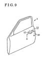
- an outside handle 11 is provided on a vehicle door 1.
- the outside handle 11 is provided at the rear side of a vehicle of a door outer panel 10 with the handle portion 12 projecting toward the outside of the vehicle.
- the door outer panel 10 forms an outer shape or profile of the vehicle door 1.
- the handle portion 12 is a member, which is gripped by a driver of the vehicle when the vehicle door 1 is mechanically opened and closed.
- the outside handle 11 is provided with the handle portion 12 and a handle frame 13.
- the handle portion 12 and the handle frame 13 are respectively provided at the outside and inside relative to the handle 10.
- the handle frame 13 is fastened to the door outer panel 10, and the handle portion 12 is pivotally connected to the handle frame 13 within a predetermined range.
- the door outer panel 10 has a bended portion 10a curving toward the inside and handle opening portions 10b and 10c are respectively provided on the door outer panel 10 at the each side respectively.
- An arm portion of the handle portion 12 is inserted in the handle opening portions 10b and 10c (the left and right sides in Fig3).
- a handle frame 13 made of resin has an approximately square shaped inside structure and is formed along the bended portion 10a of the door outer panel 10.
- the handle frame 13 is provided with two frame-side handle opening portions 13a and 13b which are respectively opened corresponding to the handle opening portions 10b and 10c.
- the handle frame 13 is respectively provided with a first internal space S1 and a second internal space S2 corresponding to the frame-side handle opening portions13a and 13b respectively.
- the handle portion 12 includes a handle base 14 and a handle cover 15.
- the handle cover 15 is provided on the handle base 14 so as to cover the handle base 14.
- the handle base 14 and the handle cover 15 made of resin form an outer shape or profile of the handle portion 12.
- the handle cover 15 is provided with a hinge arm (a arm portion) portion15a and a stroke arm portion 15b at one side (the left side in Fig3, forward of the vehicle) and the other side (the right side in Fig3, rear of the vehicle) respectively.
- the hinge arm portion 15a is inserted in the handle opening portion 10b and the frame-side handle opening portion 13a.
- a convex portion 15c forming the edge of the hinge arm portion 15a is in contact with a cover wall portion 13c of the handle frame 13 including the frame-side handle opening portion 13a.
- the handle portion 12 (the handle cover 15) is pivotally connected to the handle frame 13 with respect to a point where the convex portion 15c is in contact with the cover wall portion 13c.
- the stroke arm portion 15b is inserted in the handle opening portion 10c and the frame-side handle opening portion 13b.
- a bent portion 15j formed at the edge of the stroke arm portion 15 is engaged with a known bell crank 16 so that the stroke arm portion 15b can pivotally rotate within the predetermined range.
- the handle portion 12 is pivotally connected to the handle frame 13 with respect to the side of the hinge arm portion 15a (the convex portion 15c) within the predetermined range which set by the bent portion 15j is engaged with the bell crank 16.
- guiding grooves 13h are formed on side wall portions 13d and 13e of the handle frame 13 forming the first internal space S1 (and the second internal space S2).
- the guiding grooves 13h are provided along the assembling direction of the hinge arm portion 15a (the handle portion 12) so extends along the assembling direction from the frame-side handle opening portion 13a to the bottom side of the handle frame 13(the bottom in Fig 1). Then, the guiding grooves 13h are bent in a longitudinal direction of the side wall portions 13d and 13e.
- the hinge arm portion 15a includes side wall portions 15d and 15e extending to the bottom side of the handle frame 13(the lower side in Fig 1).
- the hinge arm portion portion15a further includes a cover wall portion 15f.
- Pair of protrusions 15i is formed on the side wall portions 15d and 15e respectively and project in opposite directions (the right and left side in Fig 2). As described later, when the handle portion 12 is assembled to the handle frame 13, the protrusions 15i are engaged with the above-described guiding grooves 13h, and then the handle portion 12 is assembled to a predetermined position along the guiding grooves 13h (that is, the assembling direction). When the handle portion 12 is located at the predetermined position, the handle portion 12 is pivotally connected to the handle frame 13 within the predetermined range.
- an internal space S3 of the handle portion 12 surrounded by the handle base 14 and the handle cover 15 is provided.
- a transmitting antenna 21, a door locking sensor 22 and a door unlocking switch 23 are accommodated.
- the transmitting antenna 21, door locking sensor 22 and door unlocking switch 23 are the electric components for the system which enhances convenience for opening and closing the vehicle door.
- the transmitting antenna 21 transmits a certification request signal to a portable station carried by a user operating the door opening and closing operation.
- the door locking sensor 22 detects a variation of capacitance when the user touches (approaches) the handle portion 12.
- the door unlocking switch 23 is a manual switch used for door opening and closing operation.
- the door unlocking switch 23 is provided with a switch button 23a and a detecting portion 23b.
- the switch button 23a is provided at the handle cover 15.
- the detecting portion 23b is provided at the handle base 14 corresponding to the switch button 23a. When the switch button 23a is pushed, the detecting portion 23b outputs a signal. In response to the signal, a door unlocking operation is performed.
- Each electrical wire extending from the transmitting antenna 21, the door unlocking sensor 22 and the door unlocking switch 23 are connected to an FFC 24(Flexible Flat Cable).
- the FFC 24 is led along the hinge arm portion 15a and functions as electrical wires in the handle portion 12.
- the FFC 24 is electrically connected to electrical wires in the vehicle (the handle frame 13).
- a guiding pawls 15g are provided so as to project in each direction which crosses at right angles as viewed in Fig.1.
- the FFC 24 is led to the outside along the hinge arm portion 15a and supported with both lateral sides being supported by the guiding parts15g.
- a bearing 15h is formed near the protrusions 15i of the hinge arm portion 15a so as to be extended through the side wall portions 15d and 15e and a box-shaped connector 17 (first connecting portion) made of resin is supported by the hinge arm portion 15a. That is, the connector 17 is integrally provided with a shaft portion 17a which projects corresponding to the bearing 15h. The shaft portion 17a is inserted in the bearing 15h, and then the connector 17 is rotatably supported by the hinge arm 15a. In the connector 17, each wire in FFC 24 is embedded.
- the connector 17 is assembled to a box-shaped connector holder 18 (second connecting portion) formed so as to correspond to the connector 17.
- the connector holder 18 is provided with terminals which are electrically connected to each wire embedded in the connector 17.
- the terminals provided in the connector holder 18 are surely electrically connected to each wire embedded in the connector 17.
- Each terminal provided in the connector holder 18 is electrically connected to the electrical wire in the vehicle body side via a cable 19.
- the connector holder 18 is loosely inserted into a concave portion 13f which is formed in the handle frame 13 at a wall portion facing to the hinge arm portion 15a. Accordingly, the connector holder 18 assembled to the connector 17 is provided so as to be pivotally rotatable relative to the handle frame 13 and so as to be pivotally rotatable together with the connector 17 relative to the hinge arm 15a. Furthermore, the cable 19 is inserted into an insertion hole 13g which extends an approximately central part of the concave portion 13f, and then connected to each terminal of the connector holder 18.
- Fig 4 illustrates the handle portion 12 which has been maximally rotated by external force from a normal state (shown in Fig 1) to a full stroke state within the predetermined range.
- the connector 17 and the connector holder 18 are pivotally rotatable relative to the handle frame 13, and further rotatable relative to the hinge arm portion 15a. Therefore, even if the handle portion 12 is rotated, the connector 17 and the connector holder 18 do not interfere with the handle frame 13, and then the electrical connection between the connector 17 and the connector holder 18 is surely maintained. Then, the electrical connection between the FFC 24 in the handle side and the cable 19 in the vehicle body side is surely maintained via the connector 17 and the connector holder 18.
- the handle portion 12 is returned from the full stroke state to the normal state (shown in Fig.1) after the external force released, the electrical connection is surely maintained as it with the foregoing case.
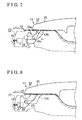
- Fig.5 to 8 illustrates an assembling process in which the handle portion 12 is inserted into the handle frame 13.
- the connector holder 18 is temporarily assembled to a predetermined position so as to be loosely inserted in the concave portion 13f.
- the connector 17 is temporarily assembled to a predetermined position so that the front edge of the hinge arm 15a can project from the front edge of the hinge arm 15a.
- the connector 17 is supported by the connector holder 18 with a frictional force between the connector 17 and the connector holder 18.
- the protrusions 15i of the hinge arm portion 15a are set to the guiding grooves 13h.
- the protrusions 15i of the hinge arm portion 15a are inserted in the frame-side handle opening portion 13a so that the protrusions 15i of the hinge arm 15 can engage with the guiding grooves 13h of the handle frame 13.
- the handle portion 12 is moved to a bended edge of the guiding grooves 13h via the protrusions 15i.
- the hinge arm portion 15a is inserted in the handle frame 13 from the handle opening portion 10b and the frame-side handle opening portion 13a (see Fig.1).
- the stroke arm portion 15b is inserted in the handle frame 13 from the handle opening portion 10c and the frame-side handle inserting portion 13b (see Fig.3).
- the protrusions 15i are displaced at the rear anchor of the guiding grooves 13h bending in a longitudinal direction of the side wall portions 13d and 13e (forward of the vehicle).
- the connector 17 is moved relative to the connector holder 18 so as to concentrically face toward the connector holder 18.
- the handle portion 12 is further moved along the guiding grooves 13h via the protrusions 15i.
- the hinge arm portion 15a is further inserted toward the cover wall portion 13c.
- the connector holder 18 is provided in the concave portion 13f, axial movement of the connector holder 18 is restricted, and then the connector 17 concentrically provided relative to the connector holder 18 is surely and electrically connected with the connector holder 18.
- the handle portion 12 is guided via the guiding grooves 13h and the protrusions 15i engaged with the guiding grooves 13g, after the hinge arm portion 15a(the stroke arm portion 15b) is inserted in the handle frame 13 via the frame-side handle opening portion 13a, the hinge arm 15a is finally assembled along a direction in which the connector 17 is engaged with the connector 18.
- the handle portion 12 when the handle portion 12 supports the handle frame 13, the assembling direction along which the handle portion 12 is assembled to the handle frame 13 is provided by the guiding grooves 13h and the protrusions 15i engaged with the guiding grooves 13h.
- the handle portion 12 is smoothly set to be supported by the handle frame 13 at the predetermined position along the assembling direction.
- the handle portion 12 can be provided and supported at the predetermined position, and then a design allowance of the handle portion 12 can be improved regardless of the handle type.
- a misalignment of the handle portion 12 relative to the predetermined position can be reduced by assembling the hinge arm portion 15a to the handle frame 13 along the assembling direction of the hinge arm portion 15a. Accordingly, looseness and twist generated by the misalignment can be reduced, and operation feeling can be improved.
- the assembling direction of the hinge arm 15a is designated by simple structure forming by the guiding grooves 13h and the protrusions 15i.
- the connector 17 can be smoothly and electrically connected to the connector holder 18 by assembling the hinge arm portion 15a to the handle frame 13 along the assembling direction.
- the connector 17 is connected to the hinge arm portion 15a so as to be pivotally movable relative to the hinge arm 15a.
- the connector 17 is rotatably supported by the side wall portions 15a and 15e of the hinge arm portion 15a.
- the connector 17 is electrically connected to the connector holder 18 so that manufacturing difference and assembling difference can be absorbed.
- the hinge arm 15a is assembled along the assembling direction without problems, and then the connector 17 is surely and electrically connected to the connector holder 18.
- the connector 17 is inserted and electrically connected to the connector holder 18 surely.
- the connector 17 is surrounded by the hinge arm 15a via the internal surface which is formed by the side wall portions 15d, 15e and cover wall portion 15f, and the shaft portion 17a corresponding to rotational axis is provided within the internal surface so as not to project to the outside of the hinge arm 15a.
- the connector 17 does not interfere with other members (the outer panel 10 and all), and electrical performance of the connector 17 can be maintained.
- the hinge arm 15a includes the protrusions 15i and the handle frame 13 includes the guiding grooves 13h.
- the hinge arm portion 15a may include a guiding grooves portion (an engaged means) and the handle frame 13 may include a protrusions portion (an engaging means).
- electrical components accommodated in the handle portion may be changed in response to a door opening and closing function. That is, the electrical components may be changed in response to a system provided in the vehicle door (an E-Latch System and Smart Entry System).
- the outside handle device may include the handle portion in which electrical component is not accommodated.
- a fixed type of handle portion is employed in the outside handle.
- an unfixed type of handle portion may be employed in the outside handle.
- An outside handle device includes a handle portion provided at the outside of a vehicle door, a handle frame fixed to the vehicle door and supporting the handle portion via an arm portion provided on the handle portion.
- the arm portion is provided with an engaging means
- the handle frame is provided with an engaged means which designates an assembling direction of the arm portion by engaging with the engaging means.
Landscapes
- Lock And Its Accessories (AREA)
Abstract
Description
As illustrated in Fig.9, an
According to the above-described embodiment, a fixed type of handle portion is employed in the outside handle. However, an unfixed type of handle portion may be employed in the outside handle.
Claims (6)
- An outside handle device comprising:a handle portion (12) provided at the outside of a vehicle door anda handle frame (13) fixed to the vehicle door and supporting the handle portion via an arm portion (15) provided on the handle portion(12) and the outside handle device characterized in that the outside handle further includes the arm portion (15) is provided with an engaging means (15i), the handle frame (13) is provided with an engaged means (13h) which designates an assembling direction of the arm portion (15) by engaging with the engaging means (15i).
- An outside handle device according to claim 1, wherein
the engaging means (15i) and the engaged means (13h) respectively correspond to a protrusions and groove which guides the protrusions, and the engaging means and the engaged means respectively correspond to a groove which guides the protrusions and a protrusions. - An outside handle device according to claim 1 or 2, wherein an electrical component is accommodated in the handle portion (12), the arm portion (15) is rotatably provided with a first connecting portion (17) electrically connected to the electrical component accommodated in the handle portion (12), the handle frame (13) is provided with a second connecting portion (18) electrically connected to the first connecting portion (17) by engaging with the first connecting portion (17).
- An outside handle device according to claim 3, wherein the first connecting portion (17) is provided on the arm portion (15) so as to be surrounded by an internal surface of the arm portion (15).
- An outside handle device according to any one of claims 1 to 4, wherein the handle portion (12) is fixedly supported by the handle frame (13).
- An outside handle device according to any one of claims 1 to 4, wherein the handle portion is movably supported by the handle frame so as to be movable relative to the handle frame.
Applications Claiming Priority (2)
| Application Number | Priority Date | Filing Date | Title |
|---|---|---|---|
| JP2003021088A JP2004232300A (en) | 2003-01-29 | 2003-01-29 | Outside handle device |
| JP2003021088 | 2003-01-29 |
Publications (2)
| Publication Number | Publication Date |
|---|---|
| EP1443164A2 true EP1443164A2 (en) | 2004-08-04 |
| EP1443164A3 EP1443164A3 (en) | 2006-10-25 |
Family
ID=32652879
Family Applications (1)
| Application Number | Title | Priority Date | Filing Date |
|---|---|---|---|
| EP20040001984 Withdrawn EP1443164A3 (en) | 2003-01-29 | 2004-01-29 | Outside handle device |
Country Status (3)
| Country | Link |
|---|---|
| US (1) | US7029054B2 (en) |
| EP (1) | EP1443164A3 (en) |
| JP (1) | JP2004232300A (en) |
Cited By (3)
| Publication number | Priority date | Publication date | Assignee | Title |
|---|---|---|---|---|
| EP1582659A3 (en) * | 2004-03-29 | 2008-12-24 | Aisin Seiki Kabushiki Kaisha | Door handle for vehicle |
| CN101555737B (en) * | 2008-04-11 | 2012-09-05 | 日产自动车株式会社 | Exterior door handle device for vehicle door |
| US20170226780A1 (en) * | 2014-08-08 | 2017-08-10 | Huf Hülsbeck & Fürst Gmbh & Co. Kg | Handle assembly for a door, door and motor vehicle |
Families Citing this family (22)
| Publication number | Priority date | Publication date | Assignee | Title |
|---|---|---|---|---|
| JP2004239008A (en) * | 2003-02-07 | 2004-08-26 | Furukawa Electric Co Ltd:The | Outside handle device and connector used therefor |
| KR100501240B1 (en) * | 2003-09-16 | 2005-07-18 | 현대자동차주식회사 | Structure of Separation Prevention of Automobile Door Outside Handle |
| EP1797960B1 (en) * | 2004-07-23 | 2014-10-15 | Aisin Seiki Kabushiki Kaisha | Door handle device for vehicle |
| US20080054649A1 (en) * | 2004-09-02 | 2008-03-06 | Matsushita Electric Industrial Co., Ltd. | Door Opening/Closing Device, Keyless Entry Device with the Door Opening/Closing Device, Vehicle Door or Building Door Carrying the Keyless Entry Device |
| JP4428388B2 (en) * | 2004-09-28 | 2010-03-10 | アイシン精機株式会社 | Antenna device and door handle device |
| TWM276736U (en) * | 2005-06-10 | 2005-10-01 | Qa Ma Internat Co Ltd | Alert indicator of vehicular door handles |
| JP4645324B2 (en) * | 2005-06-29 | 2011-03-09 | 三菱自動車工業株式会社 | Vehicle door |
| CN1924261B (en) * | 2005-08-31 | 2011-07-06 | 株式会社有信 | Vehicle door handle device |
| US7469503B2 (en) * | 2006-02-02 | 2008-12-30 | Toyota Motor Engineering & Manufacturing North America, Inc. | Outside gasket for a vehicle handle exhibiting wind redirection characteristics |
| JP4535010B2 (en) * | 2006-03-16 | 2010-09-01 | アイシン精機株式会社 | Vehicle door handle |
| JP4535014B2 (en) * | 2006-03-22 | 2010-09-01 | アイシン精機株式会社 | Vehicle door handle |
| US7934760B2 (en) * | 2009-03-24 | 2011-05-03 | Toyota Motor Engineering & Manufacturing North America, Inc. | Assist grip assemblies |
| JP5661372B2 (en) * | 2010-08-19 | 2015-01-28 | 株式会社アルファ | Vehicle door handle device |
| JP5480112B2 (en) * | 2010-11-29 | 2014-04-23 | 株式会社ユーシン | ANTENNA UNIT AND DOOR HANDLE DEVICE HAVING THE SAME |
| JP5784667B2 (en) * | 2013-03-26 | 2015-09-24 | サカエ理研工業株式会社 | Vehicle door handle device |
| JP5932708B2 (en) * | 2013-04-22 | 2016-06-08 | 株式会社ホンダロック | Outdoor handle device for vehicle door |
| CN107849866B (en) * | 2015-07-13 | 2020-09-25 | 胡夫·许尔斯贝克和福斯特有限及两合公司 | Outside door handles for vehicles |
| JP7064993B2 (en) * | 2018-08-08 | 2022-05-11 | 株式会社アルファ | Vehicle door handle |
| JP6916764B2 (en) * | 2018-08-10 | 2021-08-11 | 株式会社ホンダロック | Vehicle door out-handle device |
| JP6621521B1 (en) * | 2018-12-14 | 2019-12-18 | 株式会社ホンダロック | Outdoor handle device for vehicle door |
| JP7533257B2 (en) * | 2021-02-03 | 2024-08-14 | マツダ株式会社 | Vehicle door handle structure |
| EP4571025A1 (en) * | 2023-12-15 | 2025-06-18 | Minebea AccessSolutions France | Vehicle door handle assembly |
Family Cites Families (24)
| Publication number | Priority date | Publication date | Assignee | Title |
|---|---|---|---|---|
| US4475754A (en) * | 1982-05-10 | 1984-10-09 | General Motors Corporation | Pull out door handle assembly |
| DE4212291C2 (en) * | 1992-04-11 | 1994-08-04 | Daimler Benz Ag | Arrangement of a switching element that can be influenced without contact |
| DE29521920U1 (en) * | 1995-03-04 | 1998-10-22 | Kiekert AG, 42579 Heiligenhaus | Actuator for the door lock of a motor vehicle door |
| DE19813316A1 (en) * | 1998-03-26 | 1999-10-07 | Huf Huelsbeck & Fuerst Gmbh | Actuating device for a door lock with a foldable handle, in particular for a vehicle lock |
| DE29819472U1 (en) * | 1998-10-31 | 1999-02-18 | Kiekert AG, 42579 Heiligenhaus | Motor vehicle door lock with pull handle |
| DE19961360A1 (en) * | 1999-12-17 | 2001-07-05 | Bosch Gmbh Robert | Exterior door handle assembly for a motor vehicle door |
| DE19961370A1 (en) | 1999-12-17 | 2001-07-05 | Bosch Gmbh Robert | Outside door handle arrangement for a motor vehicle door, motor vehicle door and method for assembling an outside door handle |
| US6565134B1 (en) * | 2000-04-21 | 2003-05-20 | Adac Plastics, Inc. | Handle with side impact counterweight having installation position |
| JP3714129B2 (en) | 2000-07-14 | 2005-11-09 | アイシン精機株式会社 | Door opener |
| US6447030B1 (en) | 2000-08-25 | 2002-09-10 | Adac Plastics, Inc. | Door handle assembly with detented closed position |
| US6363577B1 (en) | 2000-08-25 | 2002-04-02 | Adac Plastics, Inc. | Motor vehicle door handle assembly with maximized bearing interface |
| DE60142440D1 (en) * | 2000-09-05 | 2010-08-05 | Valeo Securite Habitacle Sas | METHOD FOR DETECTING SIGNAL PROCESSING FOR A MOTOR VEHICLE |
| DE10051055A1 (en) * | 2000-10-14 | 2002-05-02 | Bosch Gmbh Robert | Device for initiating an opening and locking process of a motor vehicle |
| JP3569675B2 (en) * | 2000-12-14 | 2004-09-22 | 株式会社ユーシン | Automotive steering wheel device |
| US6964439B2 (en) | 2001-01-11 | 2005-11-15 | Aisin Seiki Kabushiki Kaisha | Vehicle door handle device |
| DE10121046A1 (en) * | 2001-04-28 | 2002-11-07 | Huf Huelsbeck & Fuerst Gmbh | External actuation for vehicle locks on doors, flaps or the like. |
| DE10121432A1 (en) * | 2001-05-02 | 2002-11-07 | Kiekert Ag | The door handle unit |
| DE10132925A1 (en) * | 2001-06-12 | 2003-01-02 | Bosch Gmbh Robert | Exterior door handle assembly |
| JP3794291B2 (en) * | 2001-06-29 | 2006-07-05 | スズキ株式会社 | Door handle assembly structure |
| US6854870B2 (en) * | 2001-06-30 | 2005-02-15 | Donnelly Corporation | Vehicle handle assembly |
| US6594861B2 (en) * | 2001-07-20 | 2003-07-22 | Strattec Security Corporation | Motor vehicle door handle apparatus and method of installation |
| JP4394314B2 (en) * | 2001-07-31 | 2010-01-06 | アイシン精機株式会社 | Vehicle door handle device |
| US6779372B2 (en) * | 2001-10-16 | 2004-08-24 | Robert Bosch Gmbh | Motor vehicle door lock with a lock unit and a control unit which are separate from one another |
| US6848818B2 (en) * | 2001-10-24 | 2005-02-01 | Donnelly Corporation | Vehicle handle assembly with cup lighting |
-
2003
- 2003-01-29 JP JP2003021088A patent/JP2004232300A/en active Pending
-
2004
- 2004-01-29 US US10/765,888 patent/US7029054B2/en not_active Expired - Fee Related
- 2004-01-29 EP EP20040001984 patent/EP1443164A3/en not_active Withdrawn
Cited By (4)
| Publication number | Priority date | Publication date | Assignee | Title |
|---|---|---|---|---|
| EP1582659A3 (en) * | 2004-03-29 | 2008-12-24 | Aisin Seiki Kabushiki Kaisha | Door handle for vehicle |
| CN101555737B (en) * | 2008-04-11 | 2012-09-05 | 日产自动车株式会社 | Exterior door handle device for vehicle door |
| US20170226780A1 (en) * | 2014-08-08 | 2017-08-10 | Huf Hülsbeck & Fürst Gmbh & Co. Kg | Handle assembly for a door, door and motor vehicle |
| US10612281B2 (en) * | 2014-08-08 | 2020-04-07 | Huf Hülsbeck & Fürst GmbH & Co., KG | Handle assembly for a door, door and motor vehicle |
Also Published As
| Publication number | Publication date |
|---|---|
| JP2004232300A (en) | 2004-08-19 |
| US7029054B2 (en) | 2006-04-18 |
| EP1443164A3 (en) | 2006-10-25 |
| US20040251709A1 (en) | 2004-12-16 |
Similar Documents
| Publication | Publication Date | Title |
|---|---|---|
| US7029054B2 (en) | Outside handle device | |
| US7210715B2 (en) | Door handle device | |
| US7598915B2 (en) | Bobbin for bar antenna, antenna and door handle for a vehicle | |
| US7598469B2 (en) | Vehicle door handle device | |
| EP1471194A1 (en) | A push switch apparatus | |
| JP4168104B2 (en) | connector | |
| US7140653B2 (en) | Outside handle apparatus and connector mechanism | |
| US10385593B2 (en) | Remote control for vehicles | |
| US20150247346A1 (en) | Locking lever and vehicle door opening-closing device | |
| CN113330176A (en) | Electric vehicle latch with emergency release | |
| CN101294458B (en) | Door handle device for vehicle | |
| CN1924261B (en) | Vehicle door handle device | |
| CN101752130B (en) | Housing with fixed contact and slide switch with the housing | |
| JP4595547B2 (en) | Vehicle door handle device | |
| US20040154362A1 (en) | Vehicle door operating apparatus | |
| JP6097981B1 (en) | Vehicle door lock device | |
| KR200460533Y1 (en) | Slider switch unit | |
| JP7207191B2 (en) | VEHICLE DOOR HANDLE DEVICE AND METHOD OF FIXING ELECTRONIC CIRCUIT DEVICE FOR VEHICLE DOOR HANDLE DEVICE | |
| JP5685853B2 (en) | Vehicle door opening and closing device | |
| JP3936296B2 (en) | Outside handle device and connector structure thereof | |
| CN215212876U (en) | Door lock device for vehicle | |
| JPH1064371A (en) | Lever switch for vehicle | |
| KR200454821Y1 (en) | Automotive Connector Assemblies | |
| JP4321099B2 (en) | Door handle grip | |
| JP2010138649A (en) | Door handle structure for vehicle |
Legal Events
| Date | Code | Title | Description |
|---|---|---|---|
| PUAI | Public reference made under article 153(3) epc to a published international application that has entered the european phase |
Free format text: ORIGINAL CODE: 0009012 |
|
| AK | Designated contracting states |
Kind code of ref document: A2 Designated state(s): AT BE BG CH CY CZ DE DK EE ES FI FR GB GR HU IE IT LI LU MC NL PT RO SE SI SK TR |
|
| AX | Request for extension of the european patent |
Extension state: AL LT LV MK |
|
| PUAL | Search report despatched |
Free format text: ORIGINAL CODE: 0009013 |
|
| AK | Designated contracting states |
Kind code of ref document: A3 Designated state(s): AT BE BG CH CY CZ DE DK EE ES FI FR GB GR HU IE IT LI LU MC NL PT RO SE SI SK TR |
|
| AX | Request for extension of the european patent |
Extension state: AL LT LV MK |
|
| AKX | Designation fees paid |
Designated state(s): AT BE BG CH CY CZ DE DK EE ES FI FR GB GR HU IE IT LI LU MC NL PT RO SE SI SK TR |
|
| STAA | Information on the status of an ep patent application or granted ep patent |
Free format text: STATUS: THE APPLICATION IS DEEMED TO BE WITHDRAWN |
|
| 18D | Application deemed to be withdrawn |
Effective date: 20061026 |